THÈSE
En vue de l’obtention du
DOCTORAT DE L’UNIVERSITÉ DE TOULOUSE
Délivré par l'Université Toulouse 3 - Paul Sabatier
Présentée et soutenue par
Robin ACHEEN
Le 9 novembre 2020
Détermination et impact de l'existence de décharges partielles
dans une chaîne de traction ferroviaire utilisant des composants
à base de SiC
Ecole doctorale : GEET - Génie Electrique Electronique et Télécommunications :
du système au nanosystème
Spécialité : Génie Electrique
Unité de recherche :
LAPLACE - Laboratoire PLAsma et Conversion d'Énergie - CNRS-UPS-INPT
Thèse dirigée par
Thierry LEBEY et Stéphane DUCHESNE
Jury
M. Andrea CAVALLINI, Rapporteur M. Christopher GERADA, Rapporteur Mme Sonia AIT AMAR - DJENNAD, Examinatrice
M. David MALEC, Examinateur M. Thierry LEBEY, Directeur de thèse M. Stéphane DUCHESNE, Co-directeur de thèse
Remerciements
Ce travail a été réalisé au sein de l’IRT Saint Exupéry, dans le cadre du projet HIGHVOLT du domaine Aéronef Plus Electrique, en partenariat avec le laboratoire Laplace et le LSEE, et en étroite collaboration avec l’entreprise ALSTOM. Avant même de rentrer dans le détail, je tiens à remercier toutes les personnes qui ont été impliquées, de près ou de loin, dans ce projet, et qui m’ont permis de mener à bien mon travail de thèse.
Je souhaiterais tout d’abord remercier Thierry Lebey et Stéphane Duchesne de m’avoir encadré pendant ces trois années (et quelques) de thèse. Chacun, selon son caractère et à sa manière, a su me guider et m’apporter des réponses lorsque j’en avais besoin. J’ai notamment beaucoup apprécié de travailler avec Thierry et de bénéficier de son savoir, mais aussi et surtout de sa vision et de son discernement. Il a su me motiver lorsque j’en avais besoin, composer avec ma personnalité, le tout avec beaucoup d’humour et « sans se prendre au sérieux » comme il aime à le dire. Quant à Stéphane, même si nos échanges ont étés plus brefs du fait de la distance, il m’a toujours réservé un accueil chaleureux (ce qui est appréciable à Béthune) lors de mes visites, et a su être complémentaire avec Thierry en m’apportant ici et là des conseils, connaissances ou autres analyses pour m’aider dans mon travail.
Je tiens à remercier sincèrement les membres du jury d’avoir pris le temps de lire mes travaux et pour leur présence à ma soutenance malgré les conditions difficiles.
Je voudrais également remercier Cédric Abadie de m’avoir encadré à l’IRT. En tant qu’encadrant « non-officiel », son nom apparaît moins que celui de mes directeurs de thèse, mais il est très clairement celui avec qui j’ai passé le plus de temps. Il m’a été d’une grande aide tout au long de mon travail de thèse, autant pour les aspects scientifiques que pour les aspects techniques et administratifs, et j’ai beaucoup apprécié de travailler avec lui.
De manière générale, je remercie également l’IRT de m’avoir accueilli et de m’avoir fait bénéficier d’un cadre privilégié, à mi-chemin entre les mondes académique et industriel. Je remercie toutes les personnes que j’ai pu y côtoyer, les anciens (Thibaut, Loïc, Laurent, Bouazza, Guillaume, Ludovic, Samuel…) comme les nouveaux (Mateusz, Cyril…). Merci à Gaëtan de m’avoir fait découvrir la lourdeur des blagues d’entreprise (« T’as pris ta demi-journée ? » « T’es tombé du lit ? »). Je tiens aussi à m’excuser solennellement auprès de toutes les personnes qui ont dû subir le bruit de mes manips en salle vieillissement. Enfin, j’espère qu’on aura tous l’occasion de boire un coup pour célébrer ma soutenance quand le contexte se sera amélioré !
Je tiens aussi à remercier le laboratoire Laplace, et plus particulièrement Marie-Laure, David et le groupe MDCE, de m’avoir aidé et fait profiter d’un environnement de travail agréable, même si je n’ai pas forcément été très présent. Dans une moindre mesure, je remercie également Sonia et le LSEE pour les quelques moments que j’ai pu y passer, qui ont été très agréables.
Je remercie, bien sûr, l’entreprise ALSTOM d’avoir contribué à ce projet, et de m’avoir ouvert ses portes pour effectuer une partie de mes travaux. En particulier, merci à Benali et Gérard puis Ronan de m’avoir suivi tout au long de cette thèse, et à Guillaume, Christophe et Thibault de m’avoir encadré, guidé et épaulé lors de mes essais sur le site de Tarbes.
Un grand merci à mes potes, et notamment mes amis co-thésards Jonathan, Théo et Matthieu, pour ces longues sessions de babyfoot, blind-test, mots fléchés, et bien sûr soirées qui m’ont permis de me changer les idées quand la motivation n’était pas au rendez-vous. Et bon courage pour la fin, vous êtes bientôt au bout !
Un grand merci également à ma famille, notamment mes parents qui m’ont permis d’en arriver là, et qui m’ont toujours soutenu même si ce que je faisais a toujours été un peu flou pour eux, mais aussi mon frère, et toute ma famille proche.
Enfin, je ne peux pas terminer sans remercier Paula de m’avoir supporté pendant toute la durée de cette thèse, et de me supporter de manière générale d’ailleurs, ce qui n’est pas si simple ! Merci de t’être adaptée, et pour ton soutien ! Dzięki skarbie !
Table of contents
Introduction ... 1
Chapter I. State of the art ... 4
I.1 Background ... 4
I.1.1 General context ... 4
I.1.1 Specificities of rail transport ... 5
I.2 Partial discharge mechanisms ... 6
I.2.1 Partial discharge overview ... 6
I.2.2 Type and location of PDs ... 8
I.2.3 PD detection ... 10
I.3 Electromechanical chain ... 11
I.3.1 Standard electromechanical chain structure ... 11
I.3.2 Type I/Type II machines: what is the difference? ... 12
I.3.3 Insulation system state of the art ... 13
I.3.3.1 Type I insulation systems ... 14
I.3.3.2 Type II insulation systems ... 15
I.3.3.3 Corona-resistant insulation systems ... 16
I.4 About electrical stress in machines ... 17
I.4.1 Static converters and PWM-like signals ... 17
I.4.2 Impact of using PWM control ... 19
I.4.2.1 Rising edges and non-linear voltage distribution ... 19
I.4.2.2 Overvoltages ... 21
I.4.2.3 PD measurement under PWM signals ... 23
I.4.3 SiC introduction and consequences ... 24
I.5 Consequences in terms of aging ... 26
I.5.1 Overview of aging ... 26
I.5.1.1 Definition ... 26
I.5.1.2 Modeling ... 27
I.5.1.3 Identification ... 31
I.5.2 Influence of electrical stress on PD features and aging ... 35
I.5.3 Environmental influence on PD features and aging ... 38
I.5.3.1 Thermal aging ... 38
I.5.3.2 Pressure ... 39
I.5.3.3 Humidity... 40
I.5.3.4 Mechanical aging ... 40
I.5.4 Multi-stress aging ... 41
I.6 Conclusion ... 43
Chapter II. Electrical stress identification ... 45
II.1 Purpose of the study ... 45
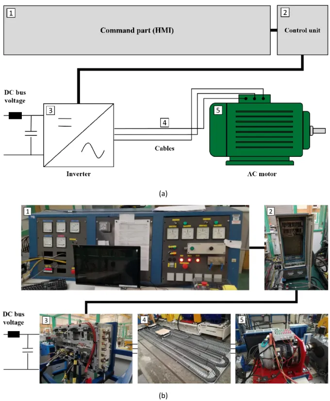
II.2 Experimental setup ... 45
II.2.1 Description of the power chain ... 46
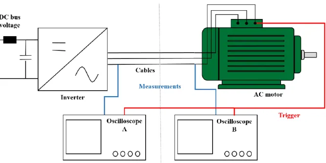
II.2.2 Instrumentation ... 48
II.2.3 Measurements and acquisition ... 49
II.2.4 Test plan ... 50
II.3 Electrical constraints in the machine ... 51
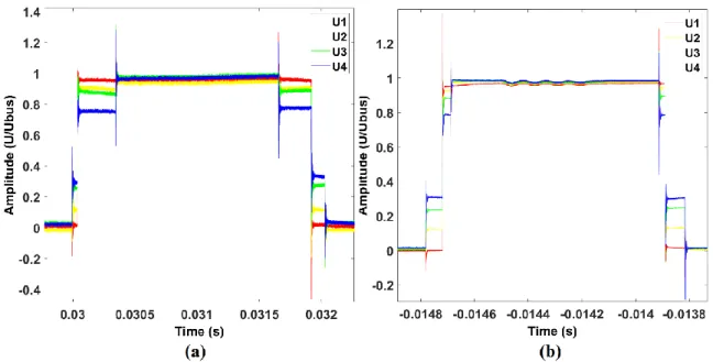
II.3.1 Turn-to-turn voltage ... 51
II.3.2 Phase-to-ground voltage ... 53
II.3.3 Phase-to-phase voltage ... 57
II.4 Influence of different parameters ... 58
II.4.1 Electrical parameters ... 58
II.4.1.1 Switched current ... 58
II.4.1.2 Rotation speed ... 60
II.4.1.3 Supply voltage ... 63
II.4.2 Cable characteristics ... 65
II.4.2.1 Cable length ... 65
II.4.2.2 Connectors ... 67
II.4.2.3 Disposition/ground plane ... 68
II.4.3 Brief overview of Si IGBT vs SiC MOSFET technologies ... 69
II.5 General summary of maximum stresses at motor terminals ... 73
II.6 Partial discharge investigations ... 73
II.6.1 Configuration no. 1: Inverter C ... 75
II.6.2 Configuration no. 2: Inverter B ... 76
II.6.3 Configuration no. 3: Inverter A ... 78
II.6.4 Key points to remember ... 78
II.7 Conclusion ... 80
Chapter III. Phenomenological study of PD activity and aging on Type I samples ... 82
III.1 Presentation ... 82
III.1.1 Accelerated aging tests: aim and procedures ... 82
III.1.1.1 How and why to perform aging tests on EIS? ... 82
III.1.1.2 Acceleration of aging ... 83
III.1.1.4 Aging procedures according to standards ... 84
III.1.2 Purpose of this study ... 85
III.2 Experimental setup and test plan ... 87
III.2.1 Samples ... 87
III.2.2 Stress generation ... 87
III.2.3 Test plan ... 89
III.3 PD monitoring protocol ... 90
III.4 Preliminary results ... 92
III.4.1 Weibull statistics ... 92
III.4.2 PD location (transient vs. steady state voltage) ... 95
III.5 Influence of the various voltage constituents on PDs and aging ... 96
III.5.1 Voltage magnitude... 96
III.5.2 Rise time ... 100
III.5.3 Frequency ... 104
III.5.4 Duty cycle ... 106
III.6 General analysis & conclusion ... 108
Chapter IV. Investigations into aging and underlying phenomena in Type II machines ... 114
IV.1 Brief introduction ... 114
IV.2 Transition from Type I to Type II conductor pairs ... 114
IV.2.1 Purpose of the study ... 114
IV.2.2 Experimental setup & test plan ... 115
IV.2.2.1 Investigation on sample characteristics ... 115
IV.2.2.2 Aging under sinusoidal stress ... 118
IV.2.2.3 Aging under square-wave stress ... 119
IV.2.2.4 Test plan ... 120
IV.2.3 Aging and PD activity: Type I vs Type II ... 120
IV.3 Extension to Type II motorettes ... 122
IV.3.1 Purpose of the study ... 122
IV.3.2 Experimental setup and test plan ... 123
IV.3.2.1 Investigations on sample characteristics ... 123
IV.3.2.2 Choice of voltage shape for aging ... 126
IV.3.2.3 Technical description of the bench ... 127
IV.3.2.4 Test plan ... 128
IV.3.3 Measurement protocol ... 129
IV.3.4 Preliminary results ... 130
IV.3.4.1 Aging and PD measurement: Type N motorettes ... 130
IV.3.4.3 Remarks ... 134
IV.4 Extrapolation to a real environment ... 136
IV.5 Conclusion ... 138
General conclusion ... 140
1
Introduction
Electrical energy is used today for many transportation-related applications, notably in the railway, aeronautic, and automotive sectors. Rationalization of this energy is a major development axis in the current “More Electrical” context. The reliability of electrical systems, especially that of Electrical Insulation Systems (EIS), therefore involves data that is crucial for ensuring that electrical equipment operates accurately over its entire life cycle. Supply systems and subsystems continue to be subject to increasingly severe electrical stresses. Issues and operating environments may differ, but there is a single common goal: reliability must be ensured and aging must be anticipated and controlled to the greatest extent possible.
This is especially true given the fact that the spread of new power converters for Adjustable Speed Drive (ASD) applications have led to new stresses with significantly more harmful impact on machines. Similarly, the introduction of SiC-based components in the electromechanical chain presents numerous advantages, but also has consequences on the reliability of insulation systems in machines. These devices can create thousands of voltage impulses per second, with extremely fast rise times. Finally, impedance mismatches between inverters, cables, and motors may lead to wave reflection phenomena that cause significant overvoltages at the motor terminals. These phenomena ignite partial discharges (PD), which are responsible for specific aging mechanisms that progressively damage the electromechanical chain’s insulation systems, eventually leading to complete motor failure. To handle these different issues, a distinction was made between low voltage (Type I) and high voltage (Type II) machines. Type I machines are not likely to be subject to PDs, unlike Type II machines which are expected to operate in the presence of PDs.
Specifically, in the context of the railway sector, Type II machines with switching frequencies up to 5 kHz and dV/dt varying from 15 to 30 kV/µs must guarantee a system lifetime of around 40 years (or 200,000 hours). The question arises regarding the margin insulation systems in current equipment may have. It is thus necessary to determine whether phenomena, particularly partial discharges that did not previously exist or were not fully understood, will appear under normal operating conditions in machines with today’s transition towards SiC-based inverters, and more precisely in turn-to-turn, phase-to-ground, and phase-to-phase insulation systems.
The objective of this thesis is therefore to study the influence of the electrical stress imposed by inverters using SiC-based components on machine insulation and, more precisely, its impact on PD activity and aging over the longer term.
This thesis is the result of three years of work conducted within the “Aging” and “Partial Discharges” teams, and as part of the HIGHVOLT project, at the Saint Exupéry Institute of Research and Technology (IRT), Toulouse, France. Furthermore, our work here was developed under the care and supervision of the “Dielectrics Materials in Energy Conversion” team at the Laplace laboratory,
2
Toulouse, France, and the Electrotechnical Systems and Environment Laboratory (LSEE) in Béthune, France. Finally, this work was also carried out in close collaboration with ALSTOM and, more generally, with all of IRT’s industrial partners.
This thesis is divided into four chapters. A brief description of each chapter is provided below.
Chapter I – State of the art
This first chapter describes the state of the art as evaluated in the early stages of this thesis work. Here, we present the general context as well as the major aspects of the topic, that is, the problem of static converters and electrical stress in machines, their influence in terms of partial discharges and, with a longer term perspective, their impact on insulation system aging. With aging mechanisms and reliability issues being of great interest in numerous areas of expertise, the state of the art is not in any way restricted to the railway sector, but rather covers electromechanical systems in general.
Chapter II – Electrical stress identification
The second chapter reports on a test campaign that performs thorough electrical stress mapping based on both geometric and electrical parameters to determine the electrical stress to which the machine is subject, and more precisely in turn-to-turn, phase-to-ground, and phase-to-phase insulation systems. The primary objective is to assess whether those constraints are significantly more stressful with SiC-based inverters with respect to conventional Si-SiC-based inverters. An analysis of the influence of various parameters on electrical stress along with partial discharge measurements are also provided.
Chapter III – Phenomenological study of PD activity and aging on Type I samples
This chapter pursues the findings of the previous chapter and presents an analysis of the impact of electrical stress on partial discharge features and aging. The different constituents of electrical stress are studied separately and a phenomenological approach that could explain their influence is presented. To help facilitate interpretation, the first step of the study is performed considering basic samples representative of Type I turn-to-turn insulation systems.
Chapter IV – Aging and underlying phenomena (Type II)
Finally, the fourth and final chapter establishes the link between the chapters II and III. It presents test results to reproduce the electrical constraints identified in the second chapter on more complex samples, representative of high voltage machine insulation systems in real environments. The purpose here is to both expand the results obtained for Type I machines to Type II machines, and to establish lifetime models and better understand the degradation of the insulation systems under stress.
4
Chapter I.
State of the art
I.1
Background
I.1.1
General context
Reliability of insulation systems in electromechanical chains is a matter common to many domains, despite the various differences that can exist between them. Regardless of those differences, the consequences of low reliability are quite similar in each case and can vary from a simple insulation fault to the total breakdown of the insulation system, eventually leading to equipment failure. Issues and priorities may change, but the activities serve the same purpose: it is necessary to increase our knowledge about the phenomena responsible for aging, in order to ensure the reliability of electrical systems throughout their entire life cycle.
In the aeronautic industry, for example, the concept of “More Electrical Aircraft” was developed with a view to increase efficiency, reliability, maintainability, cost-effectiveness, and finally to rationalize the energy on board of aircraft by electrifying systems that today use hydraulic, pneumatic, or mechanical energy [1]. The higher power density of electrical equipment is intended to drastically reduce an aircraft’s weight, as well as its fuel consumption and environmental footprint.
The emergence of this phenomenon leads to increasing demands for energy and therefore to a global increase of voltage levels, with the goal of generating and distributing more power without increasing cable weight or their section. These new voltage levels bring unknown phenomena to this industry that affect, among other things, electrical machines and, as a consequence, system reliability.
5
At the same time, ecological concerns also play a major role in thinking about the vehicles of tomorrow. In recent years, the automotive industry has been pushed to find an alternative to replace internal combustion vehicles, which are responsible for emitting a large volume of greenhouse gases and fine particles. New solutions, such as hybrid and electrical vehicles, thus emerged to meet a growing and never-ending string of recommendations. However, while that type of vehicle can be competitive regarding urban traffic, their limited operating time and long battery recharging time, not to mention financial considerations, are non-negligible obstacles to their development. One research track consists of increasing the power density of motors while ensuring a lifetime long enough to enable the vehicle to be cost-effective. With vehicle lifetime being linked mainly to the insulation system lifetime, the automotive industry faces a problem similar to that of the aviation industry, despite different stakes and challenges: combined with the use of power components, higher voltage levels compromise reliability, and system aging must be studied and optimized in order to guarantee the required reliability.
The challenge of reliability, particularly through the aging and Partial Discharge (PD) phenomena, is thus a central common point in various areas of expertise, including automotive and aeronautics fields, as mentioned previously, but also railway. It turns out that rail transport, which is the primary context of the work presented here, is somewhat different from the other cases. More details regarding its specificities are presented below.
I.1.1
Specificities of rail transport
The railway sector is quite different from other fields. Notably, most railway traction systems in Europe are electrified and aging phenomena have even more impact because the level of stress imposed on equipment is much higher. Thus, with applied voltage regularly rising above the Partial Discharge Inception Voltage (PDIV), insulation systems are permanently subject to PDs and aging.
Table 1: Electrical stress characteristics in rail transport compared to other fields Electrical constraints
Aeronautics Automotive Rail transport
AC voltage: 97-134 V / 194-268 V DC voltage: 9-32 V / 220-320 V Frequency: 360-800 Hz Rise/fall time: 0.1 µs Voltage projection: > 1 to 3 kV Batteries: 6-14 VDC HV batteries: 270-650 VDC AC voltage: around 400 V Frequency: 2-12 kHz Voltage projection: > 800 V AC voltage: up to 25 kV DC voltage: 750-3600 V Frequency: 100 Hz – 10 kHz Fundamental: up to 1 kHz dV/dt: 1-30 kV/µs Voltage projection: none
6
Reliability is not a new area of focus. Numerous studies have already been performed on the topic. However, the introduction of new fast-switching components in static converters brings a new dimension to the problem of aging. Modern converters generate voltages with rise times between 50 ns and 2 µs. Furthermore, the voltage at motor terminals depends on multiple characteristics specific to inverter architecture, control, and interaction with other elements in the chain. All this makes the entire issue of reliability equally crucial in rail transport as it is in for automotive and aviation sectors, for example, but in separate context and for different reasons. In addition, in the today’s context of global voltage increases mentioned previously, the specificities of rail transport can serve as a stepping stone and strong incentive to study the mechanisms involved in the aging of high voltage machines that will potentially be used to equip cars and airplanes of the future.
I.2
Partial discharge mechanisms
I.2.1
Partial discharge overview
A partial discharge (PD) is a fast and localized electrical discharge that only partially bridges the insulation material between a conductor’s materials or electrodes. It does not lead to the immediate breakdown of the insulation system, but it contributes to degradation via its mechanical, thermal, and chemical effects when the electrical stress exceeds a critical value called partial discharge inception voltage (PDIV). PDs occur in residual air gaps within insulation systems. These cavities may be open or closed, but the physical phenomena are similar in both cases, as these cavities are often small in size and contain a gas, generally air [3][4].
Electrostatic laws explain that electrical fields are higher in gaseous cavities than in polymer, as polymer permittivity is greater than that of gas. The molecules inside a cavity are thus subject to a very intense electric field, which sets an initial electron, originating from cosmic radiation or already present for any other reason, into motion. This electron impacts the surrounding electrons belonging to electrically neutral molecules. When the field is high enough, electrons can be snatched from the molecules and, in turn, be set into motion by the electric field. Released electrons are likely to collide with other molecules and, above a certain threshold, cause an electronic avalanche. When those conditions are met, the gas inside the vacuole is ionized.
The Townsend mechanism bests represents the avalanche phenomenon, assuming a system with two parallel plane metallic electrodes, and considering a uniform electric field. Two coefficients are necessary to formalize the Townsend mechanism:
The first Townsend coefficient, α, depicts the avalanche effect.
The second Townsend coefficient, γ, depicts the secondary emission of electrons at the cathode.
The ionization process is characterized by the first Townsend coefficient, which represents the ratio of ionizing collisions per unit length. It is important to remember that only a fraction of the collisions
7
leads to ionization. The figure below illustrates the avalanche phenomenon: when an initial electron collides with a neutral molecule, the molecule will be ionized if the electron’s kinetic energy is high enough. This ionization results in the release of a second electron and a charged particle (ion). In turn, the two electrons are accelerated and will ionize two other molecules, and so on.
Figure I-2: Diagram depicting the electron avalanche process
The first Townsend coefficient can be expressed in a variety of ways, including the following: α
P= Ae (− EB
P
⁄ ) (1)
Here, E is the electric field in V.cm-1; P the pressure in torr; A and B, respectively in (torr-1.cm-1)
and in (V.torr-1.cm-1), two constants depending on the gas. This equation expresses the ionization
coefficient in a way that is only dependent on the electrical field/pressure ratio. This simplification is often used because pressure is a parameter that does not usually modify the other parameters in the problem and is an easily measurable macroscopic parameter.
The discharge thus created by the ionization process is called “non-sustaining discharge”. It can become a self-sustaining discharge only if secondary effects complement the initial ionization. When all electrons are collected at the anode, the remaining positive ions between the electrodes move towards the cathode. If these ions have enough energy to pull some electrons from the cathode, a new avalanche develops. The second Townsend coefficient thus characterizes these secondary phenomena and represents the number of electrons snatched at the cathode by positive ions. The self-sustaining discharge condition for a distance d is therefore expressed as follows:
γ(eαd− 1) ≥ 1 (2)
If this condition is not met, the discharge stops because the number of electrons created by secondary emission does not compensate the electrons absorbed at the cathode. The secondary emission coefficient depends on the characteristics of the material at the cathode, the gas, and also the electric field. From equations (1) and (2), and by introducing the uniform field hypothesis, we can obtain the relationship between the voltage across the electrodes and the pressure-distance product:
8
V = BPd
ln ( APd ln (1 +1γ)
) (3)
Called Paschen’s law [5], this equation expresses the minimum voltage from which a self-sustaining discharge can appear depending on the pressure-distance product. The graph of this equation is referred to as the Paschen curve, in which the horizontal axis represents the Pd product, and the vertical axis represents the discharge ignition voltage. The minimum Paschen value can be found by deriving this law with respect to Pd and setting the derivative to zero. If the voltage is lower than this value, for a given pressure-distance product, no discharge can occur. Depending on the values of parameters A, B and γ, this value is about 320 V in air at standard atmospheric pressure and at a distance of 7.5 µm. Figure I-3 shows the Paschen curves obtained for different gases.
Figure I-3: Paschen curves for different gases [6]
I.2.2
Type and location of PDs
In order to address the problem of PD type and location, it is more convenient to distinguish two study perimeters: at the insulation scale, and at the machine scale. In a very general way, considering an electrical insulation system, there are four main types of partial discharge locations: internal, surface, corona, and treeing discharges [7]. (Figure I-4)
9
Discharges occurring within short gaps or small diameter cavities, such as those occluded within insulating systems in power devices and cables, may be characterized by different forms of current or voltage pulses. The discharge pulses in such gaps can be classified into two categories: Townsend-type and streamer-like discharges. The former are characterized by a lower intensity and longer width, whereas the latter are relatively narrow pulses with more rapid rise times and much higher amplitudes.
In turn, three types of discharges may be distinguished among Townsend-type discharges. In a
spark-type discharge, the breakdown proceeds along a relatively narrow channel bridging the gap. In
contradistinction to the aforementioned spark- or pulse-type discharges, pulseless or true glow
discharges occur over a widely diffused area that may encompass the entire electrode surface. They are
a discharge in which expansion of the discharge channel takes place, leading to relatively low electron densities within the diffused discharge region. Finally, the pseudoglow discharge represents a transitory condition between a true glow discharge and a spark discharge in that it possesses features common to both spark and glow type discharges. Visually, they exhibit a diffused glow within the intervening gap space. The typical voltage waveforms across a helium gap associated to these different types of discharges are shown below.
Figure I-5: Typical voltage waveform across a helium gap: (a) under pulse discharge conditions
(scale: 2 ms/div, 0.278 kV/div, gap length: 3 mm, pressure: 760 torr, applied voltage: 15 kV), and (b) with pseudoglow and true glow regions (scale: 2 ms/div, 0.139 kV/div, gap length: 0.6 mm, pressure:
760 torr, applied voltage: 5kV) [8]
In turn, the different character of the discharges affects the response of conventional partial discharge pulse detectors, which is contingent upon both the pulse shape and its rise time. In addition, discharges that take on a pulseless glow or pseudoglow form may evade detection entirely by the pulse sensing circuit.
At the machine scale, when windings are subject to large voltage magnitudes, very high electrical stresses are created at the following locations:
Between conductors of different phases Between one of the conductors and the ground Between adjacent turns
10
Depending on the voltage levels to which the machines are subject, insulation systems may not be designed to withstand PDs, or they may be brought by nature to operate with their presence. Moreover, insulation systems are not perfect and may present defects of their own, such as lack of impregnation. Misplacement and deterioration of insulation systems can also create defects. Finally, there may be areas where the electrical field, and thus electrical stress, is locally higher. These phenomena can lead all or part of the machine to be subject to PDs. Figure I-6 demonstrates two PD sites.
Figure I-6: Manifestation of glow PDs in end-winding and probably between phases (left) and in the
stator slot (right) [9]
PDs constitute one of the main degradation mechanisms in insulation systems and therefore in electrical machines. Other factors of a different nature may exist, but they are always closely linked to PD phenomena. These other factors are detailed in Section I.5.2.
I.2.3
PD detection
Partial discharge measurement allows the detection of insulation defects in various electric power devices before an insulation failure occurs. It can also help improve the insulation performance reliability of devices, and support rational and economical design, lifetime prediction, and nondestructive inspection. Measurement is not only a way to ensure that the working environment is PD-free (Type I applications), but it is also a diagnosis tool studying and monitoring the degradation of insulation systems in machines or systems operating in the presence of PDs (Type II) [10][11]. Historically speaking, PD detection has evolved in each device and power cable category. Various detection methods exist, with the main ones as follows: [12][13]
Electrical detection seeks to measure the pulse current generated by PDs. Based on the fact that an electron current flow is created at each partial discharge event, a current could be measured, with the total current depending on the number of charges transported by the partial discharge. Partial discharge currents tend to be short in duration, with rise times in the nanosecond realm. These current flows create voltage pulses across the impedance of the insulation system, which can then be measured by conventional electrical sensors.
11
Electromagnetic measurement consists of measuring the high frequency electromagnetic waves generated by PDs and propagating away from the discharge location site in the gaseous medium. The discharge spectrum ranges from a few hundred kHz to several hundred MHz. With a suitable antenna, it is thus possible to detect PDs and obtain information regarding the magnitude of the discharge and its generation point.
Optical detection is based on the fact that partial discharges also dissipate energy in the form of light. Measuring the light generated from the discharge with an adequate device, such as a photomultiplier, thus makes it possible to evaluate the discharge characteristics and provides another way of detecting and locating PDs.
Finally, the mechanical vibration and sound generated by partial discharges can be converted and detected by means of acoustic measurement methods.
There is no universality in PD detection technology that is available to all kinds of power equipment. The choice of a detection method must take into account the nature of the detection (on-line/off-line), equipment structure, surrounding noise, similarities and differences among PD detection technologies and signal processing, as well as the desired criteria for equipment analysis. Furthermore, discharges that exhibit a glow or pseudo-glow character could fail to excite the response of conventional pulse-type discharge. In practical terms, this means that the detection device choice also depends on the discharge type. In that respect, electrical and electromagnetic devices are more suited for detecting spark-type discharges, whereas optical or acoustic detection methods are preferred in the case of glow or pseudoglow discharges.
PDs and their features are heavily influenced by voltage signal characteristics, which can cause modifications in terms of the electrical field and also affect detection. It is thus necessary to take those characteristics into account and define the extent to which the voltage shape used to supply the machine could be an aggravating factor. Investigations on voltage shapes induced by static converters will be covered in the following sections.
I.3
Electromechanical chain
I.3.1
Standard electromechanical chain structure
The electromechanical chain is the overall system for converting electrical energy into mechanical energy. In the rail transport context, the electromechanical chain is the traction chain. The chain structure comprises the same elements regardless of the application, namely a source, static converter, cable network, actuator, and load put into motion by the actuator.
12
The electromechanical chain aims to receive, convert, and distribute the electrical energy. The input voltage type and level vary depending on the grid. It is thus necessary to adapt voltage in order to supply the equipment.
Figure I-7: Schematic drawing of a railway traction system (load not represented)
A converter (generally an inverter) converts the DC bus voltage from the grid into a voltage that
can be used by the actuator. Converters use power electronic components such as Silicon-based IGBTs (Insulated Gate Bipolar Transistors), which have been the benchmark in terms of controlled switches for several decades. However, wide bandgap components such as SiC (Silicon Carbide) and GaN (Gallium Nitride)-based components are gradually replacing those technologies, mainly thanks to their fast rise and fall times which considerably reduce switching losses. Inverters are usually controlled using the Pulse Width Modulation (PWM) technique. The PWM operating principle will be reviewed in the next section.
Cables make the connection between the inverter output and the machine input in order to transport
the electrical energy. Adverse effects related to cable length, nature, and disposition can occur and must be taken into account or suppressed to ensure proper machine operation.
The motor is the energy conversion element. There are several types of actuators depending on
the application. In aeronautics or automotive applications, for example, permanent magnet synchronous machines, which ensure high power density, are preferred; whereas asynchronous motors might often be used in rail transport.
Finally, filters can be placed at the inverter input or output. Filters can be convenient for various functional reasons or to meet specific standards.
I.3.2
Type I/Type II machines: what is the difference?
Rather than differentiate machines by sector and by application, it is far more convenient to distinguish them according to their operating voltage. The IEC 60034-18-41 [14] and 60034-18-42 [15] standards address this problem by proposing classification into two categories: Type I and Type II machines, depending on whether they are intended to operate with (Type II) or without (Type I) PDs at
13
any point in the insulation system. Type I insulation systems are commonly used in low voltage rotating machines (< 700V) and are composed of random-wound coils. If any part of the insulation system is likely to undergo PDs during its life cycle, the system is defined as a Type II insulation system, and subsequently it must be comprised of PD-resistant materials. Machines with a nominal voltage higher than 700V generally use Type II insulation systems [16].
This classification thus enables us to treat low voltage and high voltage machines differently. Even if aging mechanisms are the same or very similar (which is not fully guaranteed), insulation systems are not supposed to present the same behavior in the presence of PDs. Furthermore, low voltage machines generally use wound coils, whereas high voltage machines use formed-wound coils. In random-wound coils, the conductor insulation is quite thin and often surrounded by air. It may also happen that the first and last turn of a coil are adjacent to each other, leading to an increased probability of PD inception, particularly between turns, if the voltage is high enough. The erosion caused by PDs may cause unnecessary damage to the insulation system; it is therefore crucial to ensure that no PDs can occur.
Figure I-8: Illustration of partial discharge in air between several conductors under high stress [16]
In the case of Type II machines, insulation systems are reinforced with materials that are highly resistant to erosion caused by PDs. They can therefore operate in the presence of PDs; aging is not eliminated, but it is slowed considerably.
The choice of insulating materials is an important issue when designing and constructing a machine. It is thus particularly important to characterize the mechanisms associated with PDs in order to select the most appropriate insulation system. Because of the wide variety of available insulating materials, it is appropriate to review the main types of insulation typically used in machines.
I.3.3
Insulation system state of the art
In the previous section, we presented the distinction between Type I and Type II insulation systems. It is important to point out that when the operating voltage of a machine is below 700V, it may include both Type I and Type II insulation systems. However, Type II insulation systems are required for machines with an RMS voltage value beyond 700V.
Electrical insulation systems are divided into several temperature classes which specify the insulation withstand, and which are defined according to tests described in the IEC 60085 standard. It
14
should be noted that other organizations such as NEMA define the same type of standards. These thermal indexes correspond to the maximal temperature for which a material can be used for at least 20,000 hours without reaching a pre-established end of life criteria. Table 2 presents the existing classes and the associated temperature ranges according to IEC 60085 and NEMA standards.
Table 2: Definition of thermal classes according to IEC 60085 (1) and NEMA (2) Relative thermal endurance
index (°C) Thermal class (°C) Designation
90 ≤ to < 105 90 Y (1) 105 ≤ to < 120 105 A (1) 120 ≤ to < 130 120 E (1) 130 ≤ to < 155 130 B (1) 155 ≤ to < 180 155 F (1) 180 ≤ to < 200 180 H (1) 200 ≤ to < 220 200 N (2) 220 ≤ to < 250 220 R (2)
The insulation systems typically used in both types of machines, as well as their descriptions depending on their location, are given below [6].
Figure I-9: Random-wound (left) and formed-wound (right) design examples [15]
I.3.3.1
Type I insulation systemsFigure I-10 shows the insulation systems commonly used in a three-phase random-wound low voltage machine (Type I). Conductors are usually insulated with a high temperature enamel, whereas phase-to-ground and phase-to-phase insulations are comprised of aramid paper (Nomex), Nomex-Mylar-Nomex, or any other class F or higher insulation materials.
15
Enameled wire, which is widely used to build the windings of Type I electrical machines, generally features two insulation layers. The first layer, which is in contact with copper, is a polymer of the polyester imide (PEI) family and ensures good adherence to copper. The external layer consists of a polyamide imide (PAI) material that provides good mechanical properties for the overall structure. This type of enameled wire has been used widely for many years and meets the numerous mechanical, thermal, and electrical requirements of most electrical motors. The overall thickness of the insulation system depends on wire diameter and varies between 30 and 60 µm.
Figure I-10: Insulation materials in the stator windings of a random-wound machine [16]
The impregnation process can also provide complementary insulation. The initial purpose of such a process is to replace the potential air gaps in the insulation material by an impregnation liquid (generally resin or coating) that is cured afterwards in order to improve the structure’s heat transfer, resistance, and mechanical strength.
I.3.3.2
Type II insulation systemsIt is far more complex to manufacture a formed-wound stator winding and its insulation system. The different functions of the various insulation systems are detailed below.
Strand insulation aims to improve the machine’s efficiency by reducing eddy current and skin
effect losses. This insulation is typically a film coating applied on the magnet wire and/or as a Dacron glass served filament. In some applications, a polyimide tape such as Kapton can also be used.
Turn-to-turn insulation isolates the copper turns from each other. In modern motors, turn
insulation is usually a Dacron and glass composite or mica paper. Sometimes, no dedicated turn insulation is used and strand insulation fulfills both functions.
Phase-to-ground and phase-to-phase insulations separate the copper conductors from the
grounded stator core on one hand, and two different phases that can be present in a same slot on the other hand. Almost all motor stators use mica paper tape bonded together with epoxy as the ground wall insulation. These materials are almost always combined using the global vacuum pressure impregnation
16
(GVPI) process. There is usually no additional phase-to-phase insulation, as there are already two thicknesses of ground insulation present between phases.
Figure I-11: Insulation materials in the stator windings of a formed-wound machine
Complementary insulation systems may exist for some applications. A partly conductive paint
or tape sometimes covers the surface of the phase-to-ground insulation in both the stator slot area and
a few centimeters beyond each end of the core. This coating prevents PDs that could occur in air gaps between the surface of the ground wall insulation and the sides of the stator slots. It is generally used only for a rated operation voltage of 3 kV or more. Finally, a stress relief paint or tape can also be used to overlap the slot conductive coating outside the slot, extending a few centimeters into the end winding. This coating linearizes electric stress along the surface of the coil at the end of the slot conductive coating, thus reducing the risk of PDs. The coating is often made of silicon carbide powder within tape. This additional insulation system is most often applied to motors rated for 6 kV or more.
I.3.3.3
Corona-resistant insulation systemsDielectric materials used as insulators for electrical conductors may fail as a result of PDs occurring when the conductors and dielectrics are subject to voltages above the PDIV. PD-induced failure is particularly likely when the insulator material is a solid organic polymer. It has been shown that for some applications, such as railway, mica-based insulation systems are used as a solution to the problem, where the mica offers PD resistance. However, because of the poor physical properties inherent to mica, this solution is not ideal and cannot be transferred easily to other areas.
In this context, collaborative studies with the industry led to the development of polymers that are more resistant to the erosion caused by PDs. The term “corona-resistant” is used in literature [17]. These new materials are obtained by adding inorganic parts such as mica or glass to the insulation systems, as they are much harder than polymers and insensitive to the photon emission and ionic bombardment associated with PDs. Inorganic materials are added in powder form at the microscopic or nano scale
17
[18][19]. The quality of the insulation layers depends on the distribution of these micro or nanoparticles in the polymers. It is particularly challenging to obtain a uniform mixture before polymerization, especially when the inorganic powders are at the nano scale, notably because nanoparticles have high surface energy and naturally tend to form agglomerates or aggregates.
The resulting corona-resistant materials effectively prevent PD degradation of insulation leading to motor failure in normal use. Besides, the glass or mica composite occupies space in the core which otherwise could accommodate additional copper and thereby reduce the size of the motor.
I.4
About electrical stress in machines
I.4.1
Static converters and PWM-like signals
For several reasons, notably to minimize losses, it is necessary for the current flowing through the windings of an electrical machine to have a sinusoidal shape. Generally, this is possible only if the voltage signal also is sinusoidal. In the past, it was standard practice to use direct current machines for applications requiring variable speed control. Indeed, by varying voltage, it is possible to modify rotation speed accordingly. AC motors were only used for applications requiring fixed speed.
Today, generating sinusoidal signals for powering machines has become widespread and is now a reference for many reasons, including improved cost-efficiency and greater efficiency. Moreover, the harmonic content of such machines must be controlled in order to meet specified standards. Furthermore, a sinusoidal current shape makes it possible to rephase the voltage and current signals to reach a unity power factor if necessary.
In order to generate such sinusoidal signals, semiconductor components are used in association with the Pulse Width Modulation (PWM) strategy at very high switching frequencies. Speed variation is thus achieved via an inverter that generates high frequency voltage impulses with variable width at each phase in order to reconstruct a signal with varying fundamental frequency at the motor terminals, while rejecting harmonic content. The rise times associated with semiconductor components as they exist today are about a few hundreds of nanoseconds [20].
18
Therefore, static converters controlled by PWM generate steep voltage slopes that create high frequency oscillatory behaviors in machine windings. It is thus necessary to characterize those undesirable phenomena, which result in previously nonexistent dysfunctions that may affect system reliability.
Pulse width modulation is a method for controlling the average power delivered by an electrical signal by effectively slicing it up into discrete parts. Consequently, an inverter using this control method is a voltage source whose magnitude, frequency, and “shape” are controllable. Due to its structure composed of two bidirectional switching cells, the voltage inverter is reversible on the condition that this is also the case for the DC source. For most applications, the idea is to generate a sinusoidal current waveform. The rate (or frequency) at which the power supply must switch, as well as the necessity to add or not add a filtering device, can vary greatly depending on the load and application. Several types of PWM control strategies exist [21]; the choice of a strategy is mainly dependent on the supply voltage, frequency, rotation speed of the motor, and above all, the user requirements regarding harmonic content suppression, torque ripple, loss management and, more broadly, desired performance.
The simplest way to generate a PWM signal is the intersective method, which requires only a saw tooth (or a triangular) waveform (easily generated using a simple oscillator) and a comparator. When the value of the reference signal is greater than the modulation waveform, the PWM signal is in the high state; otherwise it is in the low state. The triangular waveform determines switching frequency. Several techniques exist, depending on whether the triangular waveform is symmetrical, and whether the reference signal is sampled or not. Figure I-13 shows a three-phase sampled PWM with a symmetrical triangular waveform. Only two modulation functions and the resulting modulation are represented.
19
There are several subtypes of intersective PWMs, depending on whether they are synchronous or asynchronous, analog or digital or even depending on the symmetry of the triangular waveform; for the sake of brevity, those subcategories will not be detailed here [22] [23].
Along with these two main types of PWM control, several other types of methods exist and are used for controlling electrical machines. SVM (Space Vector Modulation) is one of the most efficient advanced methods of modulation, in particular for applications with variable frequency. Its use has gradually increased in recent years due to its robust performance. Numerous types of SVM exist, and the differences between them mainly lie in their quality and implementation requirements. The main interest of this kind of strategy is the reduction of total harmonic distortion (THD) associated with fast switching of the PWM. In delta modulation, the output signal is integrated and the result is compared to limits, which correspond to a reference signal offset by a constant. Every time the integral of the output signal reaches one of the limits, the PWM signal changes state. In delta-sigma modulation, the output signal is subtracted from a reference signal to form an error signal and the output changes state when the integral of the error exceeds the limits. Direct torque control is a method used to control AC motors. It is closely related with delta modulation. Motor torque and magnetic flux are estimated and then controlled to stay within their hysteresis bands by turning on a new combination of the device's semiconductor switches each time either of the signals tries to deviate outside the band. The
pre-calculated PWM method consists of pre-calculating switching moments of power semiconductor
modules to suppress specified harmonics in the inverter output voltage. Finally, a direct full-wave
command can be used in some applications and under specific conditions, generally to take full
advantage of available voltage while avoiding or minimizing inverter losses.
I.4.2
Impact of using PWM control
Numerous studies have been performed on electrical machines supplied by static converters [24] [25] [10]. In most cases, the studies tend to show a drastic rise of the failure rate coinciding with the presence of pulse signals with increasingly fast rise times and switching frequencies. The accelerated degradation of insulation systems, and as a result that of machines, is thus a direct consequence of the use of such signals generated by PWM commands. This section presents the main impact of PWM control on voltage stress and, in turn, on a machine’s insulation systems.
I.4.2.1
Rising edges and non-linear voltage distributionLow voltage electrical machines, as highlighted above, often consist of random-wound coils whose turns can be raised to vastly different potentials during the transitional regime following the voltage rising edge. Given that the exact position of these turns in the slots is relatively random, there is a chance
20
for the first and last turn to be adjacent to each other. The probability to be in such an extremely unfavorable situation, with high potential differences between turns, is non-negligible.
Figure I-14 is the result of a statistical study [26] carried out on a slot containing 41 wires ordered in successive layers from the end of the slot. This extremely favorable case is very unlikely to occur. In order to calculate the probability of adjacency, a very large number of equiprobable selections of wire distribution in the slot are realized according to the Monte-Carlo method. The right-hand side of the figure shows the geometrical analysis of all the adjacencies for the purpose of determining the maximum turn number difference between two conductors at any point of the slot.
Figure I-14: Cross-sectional view of the slot and adjacency likelihood vs turn number difference [27]
The above graph shows that the probability of having the input conductor next to the output conductor is about 12%. It is thus necessary to ensure that the turn-to-turn insulation is able to bear the total voltage at the coil terminals.
In addition, when the machine undergoes very steep voltage slopes, the voltage distribution in the coils can no longer be considered as linear. Characterizing these high frequency effects is complex and must take into account all the parasitic effects related to these switching edges. A number of approaches can be adopted, such as the equivalent circuit method or the Multiconductor Transmission Line (MTL) theory; all these methods are based on rewriting Maxwell’s equations to take parasitic elements into account [28]. The latter (capacitance, inductance, resistance, and conductance) are most often calculated using finite element computation and integrated into numerical models of the machine. In substance, it is shown that the rising edges are less steep as the voltage propagates in the coil. The slope is thus slowed and the oscillations following the maximum voltage tend to mitigate. Hence, the voltages in the windings are distributed and handled by complex transitory regimes, especially when the relative position of each turn is unknown.
21
Figure I-15: Voltage distribution in the 41 turns of a coil [26]
I.4.2.2
OvervoltagesThe fast voltage slopes transiting through the inverter, cables, and machine can also cause overvoltage phenomena. These overvoltages should not exist in the first place, and the insulation systems are not always designed to cope with those types of stress. The wave reflection phenomenon is the main mechanism that comes into play in creating these voltage surges. To illustrate the exact meaning, a drawing of an entire electromechanical chain, including the parasitic electrical elements of the circuit, is given below.
Figure I-16: Complete electromechanical chain including parasitic elements [29]
The three main elements of the system are represented above: inverter, cables, and machine. The inverter configuration is quite standard and comprised of three legs whose switching elements are controlled individually. The series of cables is represented by a resistance, inductance, and capacitance per unit length. Lastly, regarding the motor, in addition to the fundamental parameters – stator resistance and inductance – there are also parasitic parameters in the stator windings that are essentially capacitances between turns, between phases, and between phase and ground. These parameters characterize the high frequency behavior of the system and have an influence on overvoltages at the motor terminals [29].
22
While the phenomena are considered to be very fast, the equivalent impedance of the converter is very low compared to that of the cable, the latter itself being very low compared to that of the motor for high frequencies that are likely to cause resonance. This impedance mismatch between the three elements leads to reflection phenomena at both ends of the cable whose consequences depend mainly on cable geometry and length.
Based on the reflection coefficients, the incident wave propagates through the cables towards the machine and is reflected with the same magnitude and the same polarity. Similarly, the reflected wave is reflected again towards the machine, still with the same amplitude but an opposite sign. In the figure below, the voltage wave transits four times during one oscillation period (Tosc=
4l
v with l being the cable length, and v the wave propagation speed determined with the capacitance and inductance per unit length defined above).
Figure I-17: Wave propagation through a cable [29]
Overvoltages resulting from these different wave reflection phenomena can be as high as the DC bus voltage at the inverter input. As a consequence, according to this theory, the total voltage at the motor terminals can reach up to twice the DC bus voltage. The magnitude of these overvoltages is highly dependent on cable length and voltage rise time. An example of voltage measured at coil terminals supplied by a fast-switching inverter is given below.
Figure I-18: Overvoltage magnitude vs cable length depending on rise time (left) & voltage measured
23
The main impact of this overvoltage increase in terms of amplitude, frequency, non-linearity, and rising edge, is an increase of PD activity [30][31]. A general review of the harmful effects linked to such phenomena and depending on voltage shape, among other things, is detailed in Paragraph I.5, which is exclusively dedicated to the aging of insulation systems.
I.4.2.3
PD measurement under PWM signalsPD detection is a particularly tricky problem when it must be performed in presence of very fast rise and fall times, such as those imposed by Si IGBT (Insulated Gate Bipolar Transistor) or SiC MOSFET (Metal Oxide Semiconductor Field Effect Transistor) switches. Under such operational conditions, it is crucial to select the most adequate detection tool to be able to detect PDs as effectively as possible.
The efficiency of most PD detection methods has been proven for DC or sinusoidal input voltages [32][33]. Concerning impulse voltage, however, the detection – particularly electrical detection – becomes far more complex due to switching noise. Indeed, the noise generated by power component switching tends to overlap with PD signals, which mainly occur at maximum voltage, i.e. during the rising and falling edges (Figure I-19).
Figure I-19: Overlap between PD signal and switching noise induced by an Si IGBT based inverter
[34]
Thus, the purpose of PD detection under PWM is to optimize the Signal to Noise Ratio (SNR), that is, to detect and differentiate PDs from the surrounding noise. The frequency spectrum of PDs extends into frequencies up to the GHz range, while switching noise is restricted to frequencies of only a few hundred MHz. Filtering therefore offers a viable solution for detecting PDs, provided that the cutoff frequency of the filter is adapted to the case being studied so that no PD information is lost.
As a complement to this method, other software or hardware denoising techniques, such as wavelet transform, provide excellent results and help identify PDs in the harsh conditions imposed by PWM signals [9].
24
Figure I-20: Frequency spectrum of the PD signal obtained with Fast Fourier Transform (FFT)[34]
I.4.3
SiC introduction and consequences
High frequency and high voltage generators are increasingly being used in industry for various applications. The technical requirements originating from different industrial sectors, namely high power density as well as fast switching speeds for both low voltage and high voltage systems, are pushing designers to develop new solutions to satisfy these performance criteria.
Up to this point, silicon-based MOSFET transistors have been used in low power applications for switching frequencies up to 200 kHz. For high power applications, silicon-based IGBTs have been favored for a frequency operating range up to a few kHz. However, disruptive technologies emerging over recent years such as wide bandgap components, especially silicon carbide (SiC) components, appear to be the most promising alternatives to conventional silicon-based components for high frequency applications [35][36]. These technologies allow us to increase switching frequency with significant filter reduction and/or decreasing semiconductor losses, thus leading to increased reliability and reduced maintenance costs for converters. Figure I-21 shows a synthetic dV/dt and dI/dt comparison between 3.3 kV Si IGBT and SiC MOSFET technologies.
25
Figure I-21: dV/dt and dI/dt comparison between 3.3 kV Si IGBT and SiC MOSFET technologies
Despite the numerous benefits that this technology can bring, we showed earlier in this work that the existence of very fast rising edges combined with impedance mismatches between the inverter, cables, and machine may cause severe overvoltages that could be detrimental to efficient machine operation. Figure I-22 shows voltages at the inverter output and at the motor input of a low voltage random-wound machine (5.5 kW), supplied by both Si IGBT and SiC MOSFET based inverters.
Figure I-22: Voltages at the inverter output (blue), at the motor input (green), and associated phase
26
The overvoltage and oscillations after switching are clearly visible in both cases. Nevertheless, the measured overvoltage is about 30% of the DC bus voltage with the silicon-based inverter, while about 45% for the SiC-based inverter. The influence of SiC-based components is all the more serious when the voltage slope is steep. Introducing such components in static converters is thus likely to lead to new consequences (or to consequences that had previously existed to a lesser extent). This is why quantification and understanding are absolutely necessary to effectively anticipate the aging phenomena that will eventually emerge.
I.5
Consequences in terms of aging
I.5.1
Overview of aging
I.5.1.1
DefinitionReliability is a discipline that is directly related to the study of malfunctioning in Electrical Insulation Systems (EIS) and systems in general, contributing to knowledge, prediction, and control of failure. In a very general manner, the reliability of an EIS can be defined as its ability to fulfill its function without failure under determined conditions for a given period [38].
Mathematically, the reliability of an entity at time t is expressed by the function R(t), also called the survival function. It represents the probability of failure-free operation over the time interval [0, t]. Calling T the random variable representing lifetime, reliability can be written as follows:
R(t) = Prob (T ≥ t) (4)
From this definition of the survival function, and to better understand the life cycle of an insulation system or any other component, the failure rate can also be defined. It represents the conditional probability of an entity failing between the time points t and t+dt, given that it survived until time t. The evolution of this rate over time is a very particular “bathtub curve” that highlights the different degradation phases.
Figure I-23: Failure rate over time
According to this curve, the failure rate involves three stages. The “infant mortality” stage is characterized by a decreasing failure rate. It corresponds to design or manufacturing defects, or misused
27
or insufficiently validated components. The system is generally subject to a debugging process to mitigate these failures. The second stage corresponds to component’s useful life, during which the failure rate is constant. Degradation mechanisms are time-independent during this period. Finally, the failure rate increases during the third and last stage. Failures occurring during this period are mainly due to the system/component wearing out and aging. On a broader level, failures caused by poor design, manufacturing, or installation are called intrinsic failures. Aging phenomena may be qualified as intrinsic failures. However, extrinsic failures are generally caused by misuse or improper operation due to maintenance, or as a consequence of another failure.
Aging mechanisms are numerous and diverse. They impact the insulation system primarily through the rupture of valency bonds between atoms constituting the macromolecules. EIS aging is a slow and irreversible phenomenon related to thermal, mechanical, electrical, and environmental constraints. The mechanisms involved are complex combinations of physicochemical interactions that eventually lead to a local breakdown of the insulation system.
In short, aging can be defined as an irreversible change of EIS properties when subject to stress. These constraints may be known, but their consequences and interactions are still not clearly understood. It is thus necessary to consider physical parameters in order to characterize and identify degradation. Theoretical models also exist and can be used to depict these aging mechanisms, with higher or lower levels of complexity.
I.5.1.2
ModelingStatistical modeling is fundamental in the context of studying aging. Indeed, aging tests require a large number of samples to ensure satisfactory precision. It is thus important to use the appropriate aging models. This subsection presents an overview of the standard models generally used for each type of stress. It is worth pointing out that numerous parametric models exist, with different variants and complexity. However, the very basic models used to depict electrical and environmental aging are well defined and are thus the main focus in the following presentation.
Data distribution types
In order to complement the notions previously presented, we must introduce several additional mathematical quantities. From the survival function presented in I.5.1.1, the probability density of failure at time t f(t) and the failure rate λ(t) can be defined as follows:
f(t) = dPf(t) dt = − dR(t) dt where Pf(t) = 1 − R(t) (5) λ(t) = f(t) R(t)= − dR(t) dt . 1 R(t) (6)
28
The MTTF (Mean Time To Failure) is also a good way of characterizing the reliability of an insulation system, and is defined as follows:
MTTF = E(T) = ∫ R(t)dt ∞ 0
(7)
It is extremely important to determine the most suitable lifetime distribution in order achieve data processing that is as correct as possible, but also to identify all the variable of interest in terms of reliability. Among existing statistical distributions, some are particularly relevant for lifetime studies. These are described below.
Exponential law is the only law characterized exclusively by its constant failure rate. While it is
one of the simplest laws for studying reliability, the fact that it depicts a “no memory” process with a constant failure rate makes it inappropriate for most cases. Exponential law applies to components that are not aged during a given time interval (the second stage of the previous bathtub curve) and undergo sudden failures, so there is no value in carrying out any preventive actions.
Table 3: Exponential law features
Log-normal law: A random positive variable T follows a log-normal law with parameters µ and
σ² if its logarithm follows a normal law with mean µ and standard deviation σ². As a consequence, neither the reliability function nor the failure rate have an explicit expression, but they can be calculated numerically. All parameters of the law are defined as a function of Φ, the Gaussian distribution function. This law is frequently used in the context of reliability as it applies to positive random variables. Moreover, the shape parameter σ allows a large variety of representations.
Table 4: Log-normal law features
The Weibull law is characterized by two parameters: the scale parameter η and the shape
parameter β, the latter determining failure rate variation: monotonically decreasing (0< β <1), monotonically increasing (β > 1), or constant (β=1, equivalent to an exponential law with λ=1/η). With

![Figure I-13: Example of intersective PWM for one phase of a 3-phase inverter [21]](https://thumb-eu.123doks.com/thumbv2/123doknet/2179074.10427/29.892.247.634.740.1098/figure-example-intersective-pwm-one-phase-phase-inverter.webp)