Table of Contents
Abstract (English) ... 1
Abstract (French) ... 3
General introduction ... 5
Chapter. 1: Bibliography ... 9
1.1. Renewable energy resources and importance of storage resources ... 11
1.2 Why redox flow batteries ... 18
1.2.1 Iron chromium redox flow battery ... 20
1.2.2 Bromine/Polysulphide redox flow battery ... 20
1.2.3 Vanadium/Br2 flow batteries. ... 21
1.2.4 Zn/bromine redox flow battery (hybrid flow battery)... 21
1.2.5 Zinc/cerium non aqueous redox flow battery (non-aqueous). ... 22
1.2.6 Vanadium/cerium redox flow battery. (non-aqueous) ... 22
1.3. Why all Vanadium redox flow ... 23
1.4 Challenges associated with the VRFBs ... 24
1.4.1 Membranes ... 25 1.4.2 Electrolytes ... 26 1.4.3 Electrodes ... 27 1.4.3.1 Thermal treatments ... 29 1.4.3.2 Chemical treatments ... 31 1.4.3.3 Metal doping ... 33 1.4.3.4 Electrochemical treatments ... 36 1.5 Conclusion ... 38
Chapter:2 Enhancement of the electrochemical activity of a commercial graphite felt for vanadium redox flow battery (VRFB), by chemical treatment with acidic solution of K2Cr2O7. ... 41
2.1 Introduction ... 44
2.2. Experimental ... 45
2.2.1 Materials and chemicals ... 45
2.2.2 Electrode activation... 46
2.2.3 Electrode characterization ... 46
2.2.4 Half-cell evaluations ... 48
2.3 Results and discussions ... 49
2.3.1 Cyclic voltammetry (CV) and optimization of treatment parameters ... 49
2.3.1.1 Effect of the temperature during activation with K2Cr2O7 solution ... 51
2.3.1.2 Effect of the time during activation with K2Cr2O7 solution ... 52
2.3.1.3 Effect of duration at the temperature of 140 o C ... 53
2.3.1.4 Best performing electrode ... 54
2.3.2 Linear sweep voltammetry (LSV) ... 56
2.3.3 Surface characterization ... 58
2.3.3.1 Scanning electron microscopy (SEM) ... 58
2.3.3.2 Fourier-transform infrared spectroscopy (FTIR) ... 60
2.3.3.3 Surface analysis by linear sweep voltammetry (LSV ... 61
2.3.4 Determination of Adsorption sites. ... 62
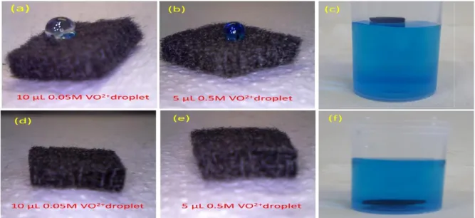
2.3.5 Wettability test ... 65
2.3.6 Half-cell evaluation ... 68
Chapter:3 Activation of the electrode for vanadium redox flow battery (VRFB) by electrochemical
treatment, chemical treatment and particle doping. ... 75
3.1 Methods ... 79
3.1.1 Cyclic voltammetry ... 79
3.1.2 Linear sweep voltammetry ... 79
3.1.3 Fourier transform infrared spectroscopy (FTIR): ... 79
3.1.4 Scanning electron microscopy (SEM): ... 79
3.1.5 Classical H-shaped half-cell ... 80
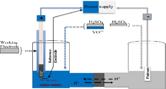
3.1.6 Pilot scale electrochemical reactor ... 80
3.2 Results and discussion ... 83
3.2.1 Activation of the electrode by the H3PO4 ... 83
3.2.2 Activation of the electrode by KOH ... 85
3.2.3 Activation of the electrode by an electrochemical treatment with (NH4)2CO3 ... 90
3.2.4 Activation of the electrode with potassium permanganate ... 92
3.2.5 Linear sweep voltammetry (LSV) for ko calculations ... 97
3.2.6 FTIR and SEM analysis ... 98
3.2.7 Surface free energy quantification of electrode ... 100
3.2.8 Charge-Discharge cycles ... 102
3.3 Conclusion ... 107
Chapter: 4 Comparative study of the role of sp3 hybridization and different oxygenal groups on the graphite felt electrodes, towards positive half-cell redox couple in vanadium redox flow batteries . ... 109
4.1 Introduction ... 112
4.2. Principle of plane wave density functional theory calculations (DFT) ... 113
4.3. Methods ... 118
4.4 Results and discussion ... 120
4.4.1 Interaction of the V(IV) with modified electrode surfaces ... 125
4.4.2 Interaction of the V(V) with modified electrode surfaces ... 127
4.4.3 Interaction of the H2O with modified electrode surfaces ... 129
4.4.4 Correlation between “sp3 hybridization ⇌ oxygenal groups ⇌ VO2+/VO2+ affinity with electrode” ... 131
4.5 Conclusion ... 134
5. Conclusion and future perspective. ... 135
6. List of publications ... 142
1
Abstract of thesis (English)
Increase of the share of renewable energy in the overall power production can ensure the future energy demand and help to cope with the environmental challenges inherent to the carbon enrich fossil fuels. Due to intermittent nature of these renewable resources, cost competitive and efficient energy storage devices are required. Vanadium redox flow batteries (VRFBs) are promising storage devices for the stationary applications due to its easy scalability, long charge-discharge cycles. The graphite and the graphite felt are low cost electrodes materials used by VRFBs which exhibits low kinetic reversibility of the redox reaction involving the system V(V)/V(IV) in the positive half-cell; this fact is responsible of significant kinetics overpotential decreasing the delivered voltage from the battery.
In this work, different methods (chemical, thermal, electrochemical,) were tried to activate the surface of commercial graphite, expecting to enhance its electro-kinetics activity, specifically for the positive half-cell reaction (VO2+⇌VO2+). The enhancement of the electro kinetic activity of
the electrode surface was characterized by the cyclic and linear sweep voltammetry. Besides the surface chemistry and morphology were analysed by the Fourier-transform infrared spectroscopy (FTIR) and Scanning electron microscopy (SEM). In another study, the electrode-electrolyte interaction was quantified by contact angle measurements allowing access to the surface free energy determination.
The activation method enables to create different oxygenal groups (C-OH, C=O -COOH) on the graphite surface and to increase the surface area. Both effects lead to i) the increase by 35 % of the current magnitude of the peak obtained by cyclic voltammetry (for the system VO2+/VO2+)
and ii) the decrease of the ΔEpeaks of the same system by 300 mV. The density functional theory
2
groups against the redox couple VO2+/VO
2+(in the positive electrode). DFT shows that these
oxygenal groups increase sp3 hybridization in the structure of the felt, that are facilitating the redox reactions.
The intrinsic heterogeneous electronic transfer constant (𝑘°) of V(V)/V(IV) system is enhanced by
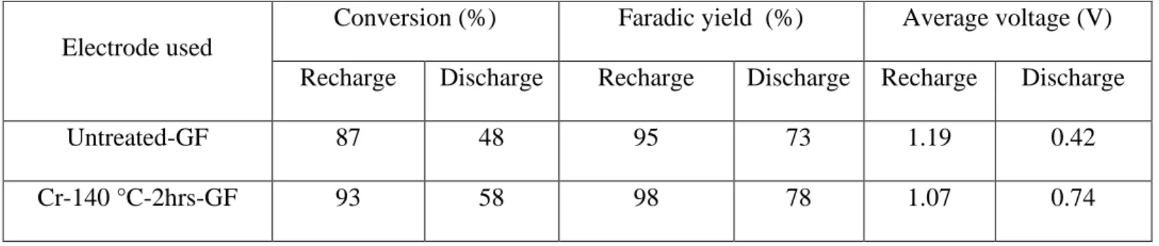
2.6 and 6.1 times for the oxidation (V(IV)→V(V)) and reduction (V(V)→V(IV)) reactions, respectively. The electrode-electrolyte interaction improves because of the increment of the surface free energy of GF from 13.9 mN/m to 53.29 mN/m. The electrode performance was evaluated in the classical half-cell by charge discharge cycles. The charging voltage decrease from 1.18V to 1.04V and the discharge voltage increase from 0.42V to 0.75V, after the activation of GF.
Proposed activation methods are novel, easy and effective. The charge discharge cycles of VRFB were performed at stack level, into the electrochemical plug flow reactor, by using 100 cm2 GF
in each electrolytic section. At a current density of 50 A.m-2, there is an improvement of 20 % and 13 % in energy and voltage efficiency (VE) of stack respectively, due to treated electrode.
3
Résumé de la thèse (français)
La demande croissante d’énergie au niveau mondial fait que les énergies obtenues de ressources renouvelables connaissent un essor important, notamment dans la production globale d'électricité propre (ne générant pas des gaz à effet de serre, tels les combustibles fossiles enrichis en carbone). La nature ‘intermittente’ de ces ressources renouvelables d'énergie implique l’utilisation des dispositifs de stockage de grande échelle, efficaces et économiquement compétitifs.
Les batteries à circulation, tout vanadium (VRFB) sont des dispositifs de stockage prometteurs pour les applications stationnaires. En effet, l’absence de contamination irréversible de l’électrolyte est l’avantage principal de cette batterie dont le nombre de cycles ‘charge-décharge’ est théoriquement illimité.
Le graphite et le feutre de graphite sont des matériaux d'électrodes à faible coût utilisés par les VRFB ; cependant le système V(V)/V(IV) (électrode positive) est cinétiquement lent sur ce
matériau et introduit une surtension diminuant la tension délivrée par la batterie. Différentes méthodes (chimiques, thermiques, électrochimiques,…) ont été conçues lors de cette thèse pour activer la surface du graphite commercial, càd. améliorer son activité électrocatalytique vis-à-vis de la réaction (VO2 + ⇌VO
2+) ayant lieu à l’électrode positive. Cette amélioration a été
caractérisée par voltammétrie linéaire (état quasi-stationnaire) et cyclique (état transitoire). En outre, la morphologie de l’électrode et son état de surface ont été analysés par infrarouge à transformée de Fourier (FTIR) et par microscopie électronique à balayage (SEM). De plus, l'interaction électrode-électrolyte a été quantifiée par des mesures d'angle de contact qui ont permis de déterminer l'énergie libre de surface.
4
L'activation de l’électrode a généré différents groupes oxygénés (C-OH, C = O, COOH) sur sa surface, laquelle a par ailleurs augmenté du fait d’une certaine érosion et donc la création d’une rugosité ; ceci s’est traduit par : i) l'augmentation de 35% de l'amplitude du courant du pic obtenu par voltamétrie cyclique (pour le système VO2+/VO2+) et ii) le rapprochement des pics anodique
et cathodique (ΔEpics= 300 mV). Les calculs de la théorie fonctionnelle de la densité (DFT) ont
été effectués pour évaluer le rôle de ces groupes oxygénés sur la réactivité du système redox VO2+/VO2+(à l’électrode positive). DFT montre que ces groupes d’oxygéne augmente
l’hybridation sp3 dans la structure du graphite, ce qui facilite les réactions redox.
La constante de transfert électronique hétérogène intrinsèque (k °) de ce même système redox a augmentée de 2,6 et 6,1 fois pour l'oxydation (V(IV) →V(V)) et la réduction (V(V) → V(IV)), respectivement. Par ailleurs l’augmentation constatée de l’énergie libre de surface du feutre de graphite (de 13,9 mN / m à 53,29 mN / m) traduit l’amélioration, par le traitement, des interactions électrode-électrolyte. La performance de l'électrode a été évaluée dans une demi-cellule classique par des cycles de charge/décharge et les résultats ont montré que la tension aux bornes durant la charge diminue (de 1,18 V à 1,04 V) alors que celle obtenue en décharge augmente (de 0,42 V à 0,75 V), après l'activation de GF.
Des cycles charge/décharge ont également été réalisés avec un réacteur électrochimique filtre presse (pile et électrolyseur pour VRFB), ayant une surface géométrique de 100 cm2 de GF dans chaque compartiment électrolytique.
Grace au traitement effectué, le rendement énergétique et la tension aux bornes se sont améliorés de 20% et 13% respectivement, dans le cas d’une électrolyse en mode galvanostatique (50 A.m2), ce qui montre que les méthodes d'activation proposées sont efficaces et en outre faciles à mettre en œuvre.
5
General introduction
Energy storage devices are an important part of the supply chain of the power energy market. The life cycle, efficiency , maintenance, capital cost are main characteristics of the energy storage systems. The selection of the energy system depends upon the nature of the application, for which it is deployed. Electrochemical energy storage devices are widely used for multiple applications such as energy management, power quality, load leveling and peak shaving. Lead acid, lithium ion, Nickel-cadmium and flow batteries etc. are some examples of electrochemical storage systems. Flow batteries has fundamental advantage over other conventional systems, because of their unique characteristics of detached energy density and power density.
Many flow batteries have been investigated in last few decades such as, vanadium flow battery, Bromine-Polysulphide, Vanadium-Br2, Zinc-cerium and iron-chromium flow battery. Due to
long life cycles and stability of the electrolyte, VRFBs are the most mature technologies. This is because of the unique property of the vanadium, that it is available in four different valencies. But there are still multiples challenges associated with it, such as cost of vanadium, toxicity and low solubility. These issues must need to be fixed to make it the cost competitive and viable option.
The stack of the VRFBs, like any other flow battery, is constituted by the electrodes, membrane, current collectors and electrolytes. All the individual components of the stack contribute in the overall ohmic losses of the stack, and consequently influence the overall efficiency of VRFBs. The electrodes are critical component in VRFBs, because the power density of stack depends on it. In addition to that, the electrodes conditioned the overall size of the stack, thus their selection, mainly conditioned by their electro-kinetic activity, is an important factor in the
6
optimization of the stack. The graphite felt is widely used electrode material in flow batteries, because it is stable in acidic condition, cheap and possess high surface area. However, it shows high kinetic polarization and could also induce electronic ohmic losses; so, it is necessary to activate it before using in the stack.
The effective and facile methods of surface treatment of the graphite felt are studied in this thesis, expecting to use the GF as the positive electrode in the VRFBs. The experiments and calculations will be performed at multiple scale, ranging from molecular to lab pilot level. The brief introduction of each chapter is as follows;
Chapter 1 presents bibliography and data analysis. In its initial part, the importance of the
energy storage devices is discussed in the realm of today power market and its environmental aspects. Then the advantages of the redox flow batteries, more specifically the all vanadium redox flow batteries, are analyzed over other convectional energy devices, and a critical study of multiple challenges associated with all the components of VRFBs was performed and pointed out the low electroactivity of the electrode against the reactions in the posolyte. The detailed bibliography was done regarding the electrode modification for VRFBs, and subsequently defined the scope of thesis
Chapter 2 contains the first experimental study done. A new activation method is proposed to
activate the graphite felt with acidic K2Cr2O7 solution, and the optimized parameters of
operational conditions are defined for this method. Initial determination of the electrode electroactivity was done by the cyclic and linear sweep voltammetry. Then the performance of the treated electrode was evaluated in a classical half-cell, containing positive electrolyte (V(IV)/V(V)), by charge-discharge electrolysis. To investigate the reason behind the improved
7
performance, that surface characterization was performed with the help of FTIR, SEM, contact angles measurements.
In Chapter 3 , the GF was tried to activate with different approaches. The objective is to explore multiple options that can provide more effective way to activate the GF for VRFBs, in taking consideration of effectiveness and easiness of the treatments. Activation of GF by electrochemical oxidation was performed in the (NH4)2CO3. Moreover, the KMnO4 derived
particle are deposited on GF to explore their catalytic ability, against (V(IV) ⇌ V(V)) reaction. The
solutions of the phosphoric acid, potassium hydroxide and potassium permanganate are also investigated for GF activation. The electroactivity of the activated GF is evaluated in the pilot scale electrochemical reactor, by charge discharge cycles.
In chapter 4, Plane wave density functional theory calculation (DFT) are performed to investigate the reason of the improvement in the electrode kinetic electroactivity. DFT calculations give the insight of the phenomena on the molecular level and can help in exploring the roles of different functional groups of the electrode surface. The software GPAW is used for setting up these simulations. Projected density of states spectra is also analyzed to explore the effect of surface morphological changes, in the electrode activation.
9
11
Chapter. 1: Bibliography
1.1. Renewable energy resources and importance of storage resources
Due to industrial growth and modern living lifestyle, the worlds demand of the energy is increasing. In the year of 2018, the increment rate of electricity consumption increase by 2.18 % [1]. Major base load of this demand is coming from the fossil fuel power plants, that are very carbon enriched. The emissions of greenhouse gases (CO2, NOx) from these power plants are
inducing serious environmental challenges and disturbing the ecological balance. After industrial revolution until now, the concentration of the CO2 increased up to 47 % in the atmosphere [2]. In
EU, the 75 % of greenhouses gases are coming from the energy sector [3]. On the other hand, the depletion of fossil fuels also poses serious question to sustainable meet of huge demand of energy, in the long term. The policy makers, engineers and technologists are extensively looking into different possibilities and alternative energy resources; that can add up magnificent junk of energy into existing installed capacity. Main aspects of all this research that alternatives resources must be environmentally friendly, economical viable and sustainable.
There is huge potential of extraction of the power from the renewable energy resources, specially from wind and solar energy. In future, these resources can arise as fundament key drivers to drift the high carbon economy towards low carbon economy, if underlying technological challenges will be resolved. The European union (EU), USA and china are extensively enhancing the installed energy capacity from wind and solar power sources. For instance, in the year of 2018, the power production in European union (EU) from the solar energy via photovoltaic cells were 3.9 % (127 TWh) of total electricity production, and this sector is providing almost 175000 jobs [4]. For future, the EU set the ambitious targets for
12
getting 32 % of total energy demand from renewable energy until 2030 and subsequently to reach the stage of complete carbon neutrality before 2050. Big milestone was achieved in the history of EU in the year of 2019, that the power generation from solar and wind energy exceed the power generation from the coal fired plants. The evolution of the renewable energy resources in the EU is shown in the fig A.1. Globally, in the year of 2019, the overall share of the renewable energies in the power production is 10.4 % . But coal is still largest producing the largest junk of the electricity, tough the production decreased by 270 TWh.[5]
13
The present infrastructure of the grid system was designed based on resources that generates consistent power, such as coal/gas fired power plants, dams and nuclear power plants etc. As the peak loads are known, so the sudden surges in demand are shaved offed by the dispatchable power generations. The renewable energy such as the solar and wind energy is the intermittent in nature and to increase the share of these resources in energy mix, the smart grid systems are required that can handle the fluctuation in the power generation; and this is possible by installing the relevant energy storage systems. The quality of power is also an import factor, for the power distribution companies. The end users have sophisticated electronic devices, and these are sensitive to the power quality. The energy storage systems can also ensure the quality of the power, during the short duration disturbances in the grid. In addition to that, the frequency regulation to the set condition are also controlled by energy storage systems. The frequency fluctuation is caused by the variable power generation from renewable and changing power load on grid system.
Above mentioned characteristics (grid fluctuation, power quality, frequency regulation) are the grid related issues caused by the variable load/power generations, and important to sort out; but more important factor to increase the share of renewables, is the sustainable power supply from these sources, and to aligned it with power demand. The energy storage devices can ensure the consistency by the load leveling and peak shaving. For instance, the energy can be stored as backup during the peak timings of the sunshine and high wind speed, and this energy could be used to shave off the peak loads in the time of high energy demand. In that way, the storage system brings the more control in the power dispatchment (align with the loads) and make the renewable power generation predicable and market able.
14
For the time being in European union (EU), the total storage capacity is approximately 5 % of the total power production. Almost similar tread of energy storage is observed globally. The storage energy systems thematically divided into following groups, based on the form of the energy they stored;
1. Mechanical energy storage system ( Flywheel; Pumped hydro etc.)
2- Electrochemical energy storage system ( Li ions battery, lead acid batteries, Flow batteries ) 3- Electrical energy storage system ( Supercapacitors)
4- Chemical energy storage system (Fuel cells) 5- Thermal energy storage system
The storage system must meet the following criteria; 1) economical, 2) efficient, 3) low maintenance cost, 4) durable, 5) withstand weather conditions, 6) environmentally friendly; so that the overall supply chain of the power generation remains cost competitive. The choice of suitable energy storage depends upon the application, for which it will be installed. The large-scale application requires the systems, having high energy capacity and discharge time. For example, the compressed air and pumped hydro storage systems can store > 100 MW and their discharge time scale lies between hours and days. The applications like power quality and frequency regulation in the smart grid application usually require the fast response and high specific power. The flywheel and supercapacitor are quite relevant choice in this regard. The response time of both devices are within the seconds., while the specific power varies between the 1000 W/Kg-2000 W/kg. [6,7] The electrochemical devices, such a Lion ion battery, lead-acid battery, fuel cells and metal air battery have the intermediate properties of the both large scale and small-scale storage devices. The power rating of these devices can be increased or decreased by adding/removing the unit cells installed. So, these systems can be used for multiple
15
application such as bulk energy management, power quality, frequency regulation, load leveling and peak shaving.
Currently, major part of this storage capacity is comprised of the pumped hydro systems . The water is pumped towards the reservoirs at high place and energy is stored in the form of potential energy. On the time of requirement, this water is passed through tunnels and turbine, to convert potential energy into the electricity. In the year of 2017, the energy stored in the pumped hydro systems was 153 GW, while total storage capacity was 159 GW. Rest 4 % of storage capacity lies in the “energy storage systems”, as shown in fig A.2. It indicates that other techniques are not matured enough “technically” or “economically”, that can be able to handle large scale energy storage, derived from the renewable resources.
16
Pumped hydro systems are very dependent on the specific high sites, on which the water reservoirs can be built. Also, these reservoirs capture a lot of the land and not good for the biodiversity. The storage devices should be near to grid station or near the power generation facility to have more distributive grid stations, while the site dependent storage systems pave ways to more centralized systems.
So, the electrochemical energy storage devices are most relevant choice in this regard and could be easily installed next to power generation sites. Different batteries have different pros and cons. For example, Lithium-ion batteries has been successfully commercialized since 1991. These batteries are extensively used into the mobiles, laptops and similar electronic applications. Due to fast response time (< 5 ms), it can also be used for the power quality maintenance. These batteries are also in focus for the mobility application such as hybrid/electric vehicles, due to its high specific energy ( 75 < E (W h/Kg) < 200) and specific power (0.5 < P (KW /Kg) < 2) [8]. The
main disadvantage of lithium ion battery for its use in the renewable integration application, is its high cost. Due to the limited number of charge discharge cycles, the replacement of the devices also induce cost in the power supply. There are also associated risk of the heat up of the battery at high temperature, and it could lead to the explosion in the worst case; because the electrodes of the battery are relatively unstable at high temperature and emitting the oxygenal gases. The renewable energy sites, particularly solar plants, has high temperatures (35 o C- 45 o C) and any instant temperature rise in battery due to high charging or any fault like that could cause problems.
The lead acid batteries are another option, that are 5 times cheaper than the lithium ion batteries [9,10] ; it consists of the cathode and anode, made up of PbO2 and Pb respectively. The rated
17
power could vary between 0 to 50 MW; and the discharge rate is in the time scale of seconds to hours. But lead batteries have certain drawback also. Number of charge -discharge cycles are low ( ≈2000), that are very important for large scale stationary applications. [8]. The low energy density (50-90 W h/Kg) is another limitation, that leads towards the problem of the space. The battery operates at lower efficiency at lower temperature; while there are the emissions of the hazardous gases at higher temperature. So the temperate control of these systems may require depending upon the environmental temperature [11]. Due to the lower energy density and lower number of cycles, lead acid battery is not feasible, neither in renewable integration nor in the vehicles. Nickel-cadmium battery is another option for the energy storage; but due to very toxic nature of cadmium, its use is strongly discouraged globally by the health and safety departments. The discarding or dumbing of these Ni-Cd batteries after finishing their lifecycle is also a big problem. There is strict restriction on its use by European union (EU) and it is completely prohibited for the consumer. The characteristics of the Ni-Cd battery is more or less the same like the lead acid batteries; but the price is 2-3 times higher than the lead acid batteries, ($1000/ [12]. These limitations are relatively less in sodium-Sulphur (NaS) batteries. These batteries contain the molten salt of the sulfur and sodium, as electrode and separated by the solid electrolyte of alumina. This battery operating temperature is around 325 o C ± 25 o C to keep the salts in the molten form. The promising characteristic of these batteries are its high energy density (150 < E W h/L < 300) and efficiency, that is around 85 %. The drawback associated with
this, is to insure its high operating temperature, its high capital and operating costs [13].
The “electrolyzer- storage system-fuel cell” combinedly form the system to store the energy in chemical form and can convert this energy into the electricity, when provided. The electrolyzer use the electrical energy from renewable sources, to convert the water into the hydrogen and
18
oxygen. The hydrogen from electrolyzes is stored into the storage tank and can be converted back to electricity by fuel cell. The hydrogen and oxygen are continuously flowed into the fuel cell and reacted to give the electric power and heat. The energy density and the power density of fuel cells are very high (500 < E W h/L < 3000). The main drawback of the fuel cell is its very low
efficiency (< 50%). The high capital and hydrogen storage cost, make this regenerative fuel cell system very expensive. [11,14]
1.2 Why redox flow batteries
The redox flow batteries are secondary storage devices that convert electrical energy into chemical energy while charging, and vice versa during discharging. The stack ( battery cell) consist of positive and negative half-cell, separated by anionic/cationic exchange membrane., as shown in fig A.3. Each half-cell contains the electrode, where the electrochemical reaction take place.
Two redox couples, having “reasonable” potential gap, are dissolved in the electrolyte stored in two different storage tanks. The electrolyte containing the redox couple with higher potential is called posolyte, while the electrolyte with the lower potential is the negolyte. In the discharge step, the reduction is occurred in the posolyte , while oxidation occur into negolyte. The storage tanks are physically separated from the cell stack.
The flow batteries have the distinguished characteristic to enables to detach energy and power densities, in contrary to conventional energy storage devices and batteries. The conventional batteries stored the electrical energy in the form of chemical energy, and chemical constitute the part of the electrode. So, the electrode is not only providing the base surface for the reaction and
19
electrode transfer, but also taking part in the reaction and undergoes physio-chemical changes in each charge discharge cycle. This phenomenon could lead towards the fast degradation of the electrodes. Also, the scalability of the conventional batteries is more complicated ; thus, to increase the energy storage capacity, another cell must be introduced. But in the case of flow batteries, the energy is stored outside of stack, in the electrode active material dissolved in the electrolyte. The quantity of dissolved electro-active material determines the energy density of
Fig A.3. The representative diagram of flow cell (fig extracted from the ref: [15])
the flow cells. The redox reaction take place at the surface electrode during charge-discharge, and power density of the cell is solely depending upon the electrode surface area and its reversibility. So, both properties, “energy density” and “power density” are totally independent of each other. The energy storage capacity of cell could be easily increase by just increasing the storage tank capacity, without changing anything in the stack. Self-discharge of the storage devices is an important factor to be studied; and in case of flow batteries, it is relatively important and induces the need to periodically equilibrating electrolytes. Also, the maintenance of flow batteries is relatively easy. In following section, flow batteries are briefly discussed.
20
1.2.1 Iron chromium redox flow battery
Iron chromium redox flow battery is the first invented battery, used by the NASA. The positive half-cell electrolyte contains the redox active specie Fe2+/Fe3+, while the negative half-cell constituted by the Cr2+/Cr3+. The following charge discharge cycles were occurring in both cells. Theocratical cell voltage of Fe-Cr is 1.18 V.
𝐹𝑒3+ + 𝑒− ⇌ 𝐹𝑒2+ E°
(Fe2+/Fe3+) =+ 0.77 V vs SHE
𝐶𝑟2+ + ⇌ 𝐶𝑟3++ 𝑒− E°(Cr2+/cr3+) =- 0.41 V vs SHE
The capital cost Fe/Cr is relatively cheaper (almost 35 $ KW h-1) than the vanadium redox flow battery [16]. The electroactivity of the positive half-cell reaction is much faster than the negative half-cell reaction. So, the negative electrode needs to be integrated with some catalyst to remove this limitation. [17–21]
1.2.2 Bromine/Polysulphide redox flow battery
The redox flow reaction of the positive and negative half-cell reaction is as below; 3𝐵𝑟− ⇌ 𝐵𝑟3−+ 2𝑒− E°(3Br -/Br
3-) = + 1.09 V vs SHE
2𝑆2− ⇌ 𝑆42−+ 2𝑒− E°(2𝑆2− /𝑆
42−)= - 0.265 V vs SHE
The anolyte is constituted by the X-Br and catholyte is comprised of the X-polysulphide. The charge exchange between both sections is maintained by the counter cation (X) exchange across the cation exchange membrane. The redox active materials are cheaper and have high solubility in the electrolyte. The drawback of this battery is the evolution of the Br2 and H2S gases at the
21
to that, the Sulphur can be precipitated in the negative half-cell, leading towards the losses of the active redox species. The sulfur could possibly be agglomerated the fibrous electrode. [18] 1.2.3 Vanadium/Br2 flow batteries.
Vanadium-bromide batteries were introduced by university of new south wales (UNSW) in 2001. The energy density of the V-Br flow battery (35-70 Wh. L-1) is almost double than the VRFBs (20-30 Wh. L-1)[22].
𝐵𝑟2− ⇌ 2𝐵𝑟−+ 2𝑒− E°( 𝐵𝑟
2− /2𝐵𝑟 −)= 1.04 V vs SHE
𝑉3++ 𝑒− ⇌ 𝑉2+ E°
(V+2/V+3) = -0.26 V vs SHE
The formation of the stench bromine vapors is the main drawback of this battery . This problem could be avoided by the adding different complexing agent in the electrolyte.[23]
1.2.4 Zn/bromine redox flow battery (hybrid flow battery).
Hybrid flow batteries partially share the same characteristics of flow batteries, in which the electrolyte is continuously flowing from the stack, that is stored in the tank outside of stack. But in contrary to flow batteries, the electroactive material of one redox system is stored into the battery as metallic form. In the Zn/Br flow battery, the electrolyte used in both cells are solution of the ZnBr2. In the negative half-cell, the Zn ions from the electrolyte is deposited on the
electrode during charging and dissolved back to the electrolyte during discharging. The representative equations are shown below;
2𝐵𝑟− ⇌ 𝐵𝑟2+ 2𝑒− E°= + 1.09 V vs SHE
22
Though, the energy density of Zn-Br (70 Wh. L-1) and OCV (1.8 V) is greater than the VRFBs
[24].; but the adsorption of Zn on the electrode (usually graphite felt ) is complicated. Technically there are two different phenomena are involved in this reaction. One step is concerned the adsorption of Zn on the electrode and second step is the electron transfer. The Zn adsorption affinity are limited on the carbon electrodes; and its uniform adsorption on electrode is also questionable [25]
1.2.5 Zinc/cerium non aqueous redox flow battery (non-aqueous)
The redox flow batteries mentioned before, are aqueous redox flow batteries. Different chemistries of non-aqueous redox flow batteries are also discussed by employing the electrolyte, that has wider potential window than water. For example, the Zn/Ce redox couple have the wide potential window gap with the OCP 2.51 V. The representative equations are as follow;
𝐶𝑒3+⇌ 𝐶𝑒4+ + 𝑒− E° = +1.28 -1.76 V vs SHE
𝑍𝑛2++ 2𝑒− ⇌ 𝑍𝑛 E° = -0.76 V vs SHE
Instead of water, the organic acid CH3SO3H is used as the electrolyte. The low conductivity and
its stability are main drawback of this flow battery. [26,27] 1.2.6 Vanadium/cerium redox flow battery. (non-aqueous)
The V-Ce chemistry was proposed for flow batteries, in aqueous, as well as in non-aqueous phase. The theoretical voltage is also high as per following equations.
2𝐶𝑒3+⇌ 2𝐶𝑒4+ + 2𝑒− E° = +1.28 -1.76 V vs SHE
23
The cell voltage in the aqueous sulphuric acids is high ( 1.8 V), in comparison with the VRFBs (1.26 V), but the solubility of Ce is less than 0.3 mole. L-1 [28]. The low solubility of Ce limits the applicability of the Ce-V redox flow battery, despite of its high cell voltage. The solubility of the Ce is increased up to the 0.8 mole. L-1 in the mixed organic media of methane sulfonic acid [29], In that way, the theoretical energy density of the V-Ce approaches to the 27.7 Wh L-1. But the conductivity and stability of the organic acids is the main drawback.
1.3. Why all Vanadium redox flow
In all vanadium redox flow battery, the catholyte and anolyte both consist of the vanadium salt compounds. Vanadium element has unique property to exists in four difference valance states i-e “V(II), V(III), V(IV), V(V)”, having the required redox potentials to constitute the redox system, so
that it can be used in the energy storage application. Prof Skyllas Kazacos from university of new south wales (UNSW) proposed the idea of all vanadium redox flow batteries. The V(II)/V(III) constitutes the negative couple, while the positive half-cell electrolyte contains the V(IV)/V(V) redox system. The respective reactions occurring in both half cells are as below;[30].
Positive electrode: 𝑉𝑂2++ 2𝐻++ 𝑒− ⇌ 𝑉𝑂2++ 𝐻
2𝑂 E°(VO2+/VO2+) = 1.00 V vs SHE;
Negative electrode: 𝑉3++ 𝑒− ⇌ 𝑉2+ E°(V2+/V3+) = - 0.26 V vs SHE;
For the large-scale energy storage applications, the long-life cycles and stability of the electrolyte is important. The electrolyte is stable in the VRFBs, because the same metal ions is used in both half cells. Even if there is some cross contamination between both half cells with the time, there is not any need to change the electrolyte. The regeneration of the electrolyte can be obtained by providing the required charge to the battery at low constant current density. The VRFBs shows
24
the stable performance over large number of cycles (10000-14000), in comparison with the lithium ion batteries and lead acid batteries. [31].The vanadium redox flow battery has already been successfully commercialized in several countries for multiple application. In 2005, the 4 MW capacity plant was built at Hokkaido japan for storing the energy from wind power plant [22]. The China is building the world largest VRFBs energy storage system, in the wind power plant (Dalian China), having the capacity of the 200 MW [32]. The low energy density of the VRFBs limits its use in the mobile applications, and it is only considered for the stationary applications. As already explained, the lower energy density of flow batteries in the stationary applications could be compensated by increasing the volume of the electrolyte in the storage tanks.
1.4 Challenges associated with the VRFBs
There are multiple challenges associated with VRFBs to make it more viable option for stationary energy storage application [33] : 1) The ohmic resistance caused the membrane and the electrolytes. 2) the electronic resistance of the electrode (graphite felt in contact with massive graphite) 3) The cost of the individual components. 4) The kinetic polarization of the reactions on the electrode surface. 5) The mass transfer limitations due to internal geometry, flow rates and the concentration of the electrolyte (causing the pressure drop) [34]. All these factors influence the power density and cost of the stack and it is very important to optimize it [35]. By improving the power and energy densities, the size of the stack required, decreased and consequently all the internal elements (electrodes, membranes, current collectors etc) used are of smaller size. So, the overall cost of stack decrease, and efficiency of the overall VRFBs increased. The bibliographic review of tackling these challenges, related to important components of the stack (membranes, electrolyte and electrode), are as below.
25
1.4.1 Membranes
Membranes are very important component of the VRFBs, enabling to avoid the cross mixing of both half-cell electrolytes, while allowing the protons transfer for the charge balance for the cationic membrane. It must possess the high mechanical and chemical stability at the variable flowing rates of acidic electrolytes. There are many fluoride and non-fluoride membranes, that are explored by the researchers, in the VRFBs application [36–45]. Among them, some membranes (cationic) enable the H+ transfer, thanks to the HSO3- functional groups grafted on
the alkyl groups of the polymer. Some other membranes (anionic) allow the OH- transfer by surface migration via NH4+ functional groups grafted on the polymer.[45,46] There is the
production of H+ on the positive half-cell while charging and vice versa, so it is more general to use the cationic exchange membranes, to exchange H+ ion. Nafion membrane are perfluorinated
sulfonic acid cation exchange membranes, having good stability against acidic anolyte and catholyte of VRFBs; also, it ensures high permeability of protons to maintain the charge balance. But these membranes are expensive, and in addition they suffer from a significant permeability loss of the vanadium, causing the self-discharge of battery. [22,47]. To avoid the problems of the vanadium permeability, some researcher did modifications in nafion membranes: for instance, the nafion is successfully modified with polytetrafluoroethene (PTFE) and silica [48] . Qiu et al. modified the nafion membrance with impregnating multiple layers of polyelectrolyte polymers.[49]Similarly, the nafion is modified by SiO2 [50], TiO2 [51] to decrease the vanadium
permeation and to increase the proton transfer. All the modified membranes were evaluated at the operational conditions of the vanadium flow cell while charge-discharge, showing better protons ions conductivity and less vanadium permeability. Many researchers fabricate and explored the non-fluorinated membrane also to find the cheaper and more efficient substitute.
26
The polymers used are sulfonated poly(ether ether ketone) (SPEEK) and poly- benzimidazole, [38,41] but these polymers are susceptible to chemical changes in the acidic environment and lose their efficiency with time. This behaviour leads to the lowering the life cycle of the VRFBs. [52,53]. So currently commercial nafion membrane, even with its higher price, are most widely used membrane in VRFBs.
1.4.2 Electrolytes
The selection of electrolyte and its concentration affects the energy density and the ohmic loses; moreover, it also influences the reaction kinetics on the electrode surface, consequently effecting the energy efficiency. There are certain challenges, that are associated with the electrolytes about the solubility, stability and viscosity. Thee optimum concentration of 3 M -5 M H2SO4 solution
is used as base electrolyte in VRFBs [54], for the concentration of 1.5 M to 2 M vanadium. The solubility of the vanadium salts, specially the V2O5, is low in the acidic aqueous media and
decrease with the increase of the temperature. For the species V2+, V3+, V4+, the solubility increases with increasing temperature and vice versa. At the concentration of 1.5 M, precipitation of V(V) starts over the 40 oC ; while for the other three vanadium states, “V2+, V3+, V4+”, precipitation starts before 10 oC. Thus, for all of four vanadium compounds the solubility
remains lower than 1.5 M in the temperature range of 10 o C to the 40 o C
To increase the solubility beyond this temperature range (10 oC - 40 oC), many researchers
investigate the addition of some additives[55,56]. Other possibility is to install some heating/cooling device to maintain the temperature of the stack, but this option increases the complexity of the system and introduce additional cost and energy losses. Some researcher investigate the chloride based electrolytes in place of the H2SO4 for the better solubility of
27
vanadium; but in the case of HCl, there is the eventual risk of the production of the Cl2 gas
[57,58]. Skyllas et al. investigated the addition of the ammonium sulphate and ammonium phosphate in the H2SO4 solution. The results indicate that the 2 M concentration of the vanadium
is stable up to the 45 oC and battery showed the stable performance around 120 to 150
cycles.[59].
1.4.3 Electrodes
The power density of the (VRFBs) stack highly depend upon electro kinetic activity and active surface area of the electrodes. Many electrodes have been studied for the vanadium redox flow application. The following characteristics is taking under consideration while selecting the electrode material; 1) the fast kinetics against redox reaction over the long time 2) mechanically stable against the flowing conditions. 3) should be chemically stable in the acidic conditions (3 M – 5 M H2SO4). Also, the positive electrolyte contains VO2+ in fully charged state and it is
strong oxidizer. 4) The cost should be cheap, so that the capital cost of the overall system remains economical.
Generally, carbon based 2-D and 3-D electrodes are used in the VRFBs applications, such as graphite plates, carbon paper, carbon cloth, carbon felt. The other materials are also used such as platinized titanium sheets, carbon nano tubes composite[60–70]. Among these electrodes, graphite felt (GF) is the fibrous 3-D electrode, having highest surface area per unit volume ≈ 22100 m2. m-3 [71]. The high porosity, good electrical conductivity and low prices also made GF electrodes most popular choice for the VRFBs application. Rest of electrodes have 2-D dimension and have less available area for the redox reactions.
28
There are few disadvantages associated with the GF. High pressure drops and possible channeling of electrolyte in the porous structure of the felt can affect the loss of efficiency of the stack. The different flow field geometries and channel can eliminate this problem, such as serpentine flow field.[72–74]. The electroactivity of the vanadium reactions is also relatively slow on the GF electrode [75]. The properties of the graphite felt depends upon the starting precursor material; from which they fabricate. Polyacrylonitrile (PAN) and cellulosic rayon are mostly used to synthesis the GF, by the following procedure. 1) The initial precursor in polymerized and oxidized to form carbon fiber. 2) Then it is converted into the polymer felt, subsequently carbonized around 800 oC to get the carbon felt. 3) The final graphite felt is obtained by graphitizing the carbon felt at the 1600 oC [71,76,77]. Various activation procedures can be used to increase the electroactivity of electrode; such as thermal , electrochemical and chemical treatment. The insertion of the different metal oxides on the electrode surface is also investigated by many researchers. The detailed bibliographic analysis of various activation methods is discussed in the following sections.
The design of the electrochemical reactor depends upon the slowest reaction. Bibliography shows that the kinetics study of both half-cell reactions is widely investigated to determine the rate limiting reaction. Sun et al. proposed the mechanism for both half-cell reaction, as shown in the fig A 4. According to the proposed mechanism, the positive half-cell reaction involves two steps: the proton exchange / VO2+ adsorption, and electron transfer step. On the other hand, negative half-cell reaction contains the single electron transfer step. So, positive half-cell reaction seems to be the more complex chain than negative one and act as the rate limiting reaction. Zhong et al. and Gattrell et al. quantitively analyzed the reactions rates on the carbon electrode, that shows the positive cell reaction is comparatively slow than the negative
half-29
cell reaction. [23,75,78]. So, the positive half-cell electrode requires the activation to increase its electroactivity, so that the kinetics polarization of the reaction on the electrode surface decreased. In the following sections, bibliography of concerned different treatments, are critically analyzed.
Fig A.4. The mechanism of both half cells on the electrode surface (fig extracted from the ref:[79])
1.4.3.1 Thermal treatments
Skyllas et al. [80] investigated the thermal treatment effect on the graphite felt (GF) for VRFBs. The electrode was heated at the different temperatures (200 oC - 600 oC) and for different durations (10 h -50 h), to find the optimized conditions, at which the electrode shows the better performance. The activation at 400 oC for 30 hours in the air, showed improved kinetics of the
30
electrode. As the temperature increase beyond 400 oC, the weight loss is too pronounced because
of the burning of the surface. i.e. from 1.06 % to 11.02 %. X. Wu et al. [81] treated the graphite felt with the microwaves, that increased the voltage efficiency by 3 %. In another study, Chen-Hao Wang et al. [82] proposed the activation method by the steam at 700 0C. The resulted energy efficiency increased by the 5 %. The steam at high temperature undergoes the reforming reaction and insert the roughness and the oxygenal functional groups.
Min-Sik Park et al. [83] applied oxygen plasma and Gamma-ray irradiation in two different experiments to investigate the effect on the surface morphology of the carbon felt and their activation against VO2+/VO2+ redox couple. The thermal treatment and oxygen plasma treatment
change the surface morphology of the carbon felt, but the Gamma-ray irradiation do not have visible effect on the surface morphology. The oxygen plasma alone has limited penetration in the porous structure of the carbon felt and has a non-uniform surface effect. The Gamma-ray irradiation change the surface chemistry of the carbon felt, by converting the already present carboxyl and carbonyl group on the felt surface, into the phenolic group; without changing the physical structure of the carbon felt. Specifically, this treatment breaks the C=O bond and creates the free radical on the surface and enables grafting of the phenolic group on the surface. The overall cell energy efficiency was improved by 7 %.
Chen-Hao Wanget et al. [84] employed a constant flow of CO2 at high temperature of 1000 o C
in tubular furnace, to activate the graphite felt by the VRFBs. The C=C bond is converted to the C-O, C=O and the C-OH. Tao Liu et al. [67], used the same treatment procedure (by CO2) for the
activation of the carbon paper; they chooses higher operational temperatures i-e 1000 oC-1500 oC.
31
1.4.3.2 Chemical treatments:
M. Skyllas-kazacos et al. [85] investigated the activation the graphite felt in the 98% concentrated H2SO4 . The dipping of the graphite felt into the acid at room temperature for one
day, did not alter the surface of the electrode, and the resulted GF did not showed any improvement against redox reactions. The effect of different concentration of H2SO4, from 50 %
to 98 %, was studied at their boiling points (≈ 300o C) up to 15 h. The concentration below the
90% has not any impact on the electrode, while the heating in 98 % H2SO4 at its boiling point for
5h successfully activate the electrode. The weight losses start by H2SO4 treatment even after
1-hour but become very pronounced effect after 10 1-hours. For the same duration, the 70 % HNO3
treatment was also applied on the GF at its boiling point. Though, the activation performance is better than the untreated electrode, but it is lower than the H2SO4. [85]. Possible reason of this
different performance is concentration of the both acids e-y the H2SO4 used was 98%, while
HNO3 used was 67 %.
Lu Yueet al. [86] used both acids (H2SO4 98 % + HNO3 67 %) in the different proportions. The
mixed acids show better treatment, than the treatment with the individual nitric acid and Sulphuric acid. Because when the mixed acid applied for the oxidation, the nitric acid starts acting as the oxidant and sulphuric acid starts catalysing the process. This synergetic phenomenon enhanced to maximum extent when the ratio of the sulphuric acid and the nitric acid used in ratio of 3:1 (V/V).
Chao Gao et al. [87] exploited the highly oxidative power of Fenton reagent to activate the graphite felt. The Fenton reagent is widely used in the advanced oxidation processes in rectification of the organic pollutants from the wastewater. The hydroxyl radicals are produced
32
by the decomposition of H2O2 in the presence of the iron catalyst. The C=C and the C-H bonds
on edge of the graphitic structure was oxidized, the C-H bond convert to C-OH, the C=C bond was converted to the C-C-OH. Upon further oxidation the -OH groups further oxidized to the C=O.
X. Wu et al. [88] activated the graphite felt by modified Hummers method. The hummers process has series of interconnected chemical steps, and even minor deviations from the operational parameters, may lead to structural damage of the electrode or coverage of the surface with different proportion of the functional groups. Jingyu Xi et al. [89] created the micropores and oxygenic groups on the graphite felt by KOH pyrolysis at high temperature in inert environment. The micropores are created in the range of 2 nm. The oxidation of the graphite felt is because of the reduction of the hydroxide. The proposed reaction for the KOH enabling the creation of micropores are as follows (6KOH + 2C → 2K + 3H2 + 2 K2CO3 ) [90]. Some part of
the carbon is consumed in the formation of the K metallic, create the new surface by creating flakes on the carbon surface. The mesopores are formed due to the intercalation of the metallic K in the graphene layers. The overall fibrous structure could be destroyed by severe experimental conditions. All the experiments were done in the nitrogen environment, because the carbonization of these reactions is occurred usually above 600 0C and at this temperature, the felt would be burned in the presence of the air.
The role of nitrogen groups on electrode were also studied by several researchers. Yuyan Shao et al. [91] developed the mesoporous carbon with nitrogen doping and insert it on the base carbon electrode material. The nitrogen doped content showed the positive effect in catalysing vanadium redox reactions. The nitrogen groups that doped on the surface was pyridinic-N, Pyrrolic-N, quaternary nitrogen (graphitic nitrogen) and N-oxides of pyridinic-N. Graphitic nitrogen is the
33
compound that is pinched in the graphene layer and replace one carbon atom from the graphene structure. Carbon atoms near to nitrogen atoms contains high positive charge density due to the electronic affinity of nitrogen atoms. These adjacent carbon atoms act as active sites to enhance the redox reaction. The induction of the nitrogen compounds creates charge delocalization in the structure. This delocalization improves the adsorption of the V-O complexes on the surface and facilitate the VO2+/VO
2+redox couple. The procedure of nitrogen doping on carbon
nanomaterials require high temperature i-e 850 0C . Tao Wu [92] doped the nitrogen directly on the graphite felt to avoid these limitations. The doping was done by heating the felt at 180 oC in
25% ammonia for the 15 hours, in the airtight closed autoclave. The inherent oxygen groups on the bare graphite felt was converted to the nitrogen compounds like amide groups. The NH3
reaction does not affect the morphology of the electrodes. After treatments, carbon fibres become more smother than the untreated carbon, because of the cleansing effect of the ammonia. The hydrophilicity and absorptivity of the treated samples were improved, in comparison with the untreated felt; that clearly indicate the nitrogen affinity towards vanadium species. Because the ammonia does not affect the surface area of the graphite felt, so all the hydrophilicity and absorptivity were caused by the nitrogen compounds.
1.4.3.3 Metal doping
M. Skyllas-kazacos et al. [61] investigated the electro catalytic activity and reversibility of the glassy carbon , graphite fibers and residual graphite fiber oxide to use as electrode in the vanadium redox flow batteries. They also impregnated different metallic cations i-e Pt+4, Pd+2, Au+4, Mn, Te+4, In+3 and Ir+3 on the residual graphite fiber oxide to have better electrochemical
active electrode materials. The rGO fiber impregnated with Pt showed the same electrochemical behaviour towards vanadium redox reactions as the Pt+4 itself. The reversibility of electrode is
34
significantly improved due to the Pt metal active sites (PtO / PtO2) on the electrode. The Te+4,
In+3 and Ir+3 showed better performance as compared to the Pt, Pd. Among all these metals, the Ir+3 impregnated electrode showed best performance. The peak current of CV current increased by 10% , but the formation of O2 and H2 bubbles is the main draw back
W.H. Wang et al. [68] investigated the IrO2 modified carbon felt by the reduction of the H2IrCl6.
The results indicate the improved electronic conductivity, because Ir deposition improves the fibre to fibre contact,. The main drawback of this treatment is that it is too lengthy and complicated process. It almost required 35 hours to treat the electrode. Young-Jun Kim et al. [93] investigated the effect of Mn3O4 nanoparticles on the Carbon felt. The effect of the Mn3O4 is
more pronounced towards VO2+/VO2+ than the V2+/V3+ couple.
Cristina Flox et al [65] investigated the hydrazine treated graphene supported bimetallic nano-CuPt3 on inert material to use as positive electrode for VRFBs. The base material was
prepared by injecting hydrazine treated graphene oxide on the inert material. To enhance the electrochemical activity of this material, the CuPt3 particles were impregnated on graphene oxide
base electrode. Hydrazine treated Graphene supported monometallic Cu nanoparticles and mono metallic Pt were also investigated separately for the comparison purpose, but the bimetallic particles CuPt3 showed better performance than the both individual metals. The -OH groups on
the bimetallic nanoparticles are believed to be the reason of this enhancement. The control of the particle size distribution is difficult to be achieved in this treatment. The durability and stability of these particles with the flow of the electrolyte could also limit the performance of the electrode: the costly platinum metal increases the overall cost of the electrode and the presence of the Cu particles makes the electrode less stable in the acidic conditions.
35
T.S. Zhao et al. [94] deposited the Copper sulphate nanoparticles on the graphite felt to use it as the negative electrode in the VRFBs. The Cu2+ nanoparticles are introduced into the negative electrolyte in the form of the CuSO4. The standard potential of the Cu/Cu2+ is in between the
potential of the VO2+/VO2+ and the V3+/V2+. Before the system approaches the V3+/V2+reduction
potential, the Cu+2 reduces and electrodeposits on the graphite felt. Then metallic copper is oxidized back into the Cu2+ ions before the system approaches the potential of the VO2+/VO
2+.
This indicates that the Cu particles could only affect the kinetics in the electrodeposited form, not in the ionic form. The Columbic efficiency of the cell increase with the increase of the Cu+2
concentration up to 0.005M; consequently, affects the kinetics of V3+/V2+. This is because copper consumes some factor of the flowing current. The Voltage efficiency of the cell also stop increasing further after the 0.005M. This phenomenon arises, because the Cu nanoparticles agglomerates and loses its nano size distribution and converted to the micro particles on the electrode. That clearly indicate the limitation of the stability of the nanoparticles on the graphite felt. Moreover, the Cu2+ in the electrolyte also subject to number of the side reactions in the cells. Wei Wang et al [95] investigated the graphite felt doped by bismuth nano particles.The results showed that the V3+/V2+ couple kinetics is more sluggish than the VO2+/VO
2+ in the presence of
the HCl solution electrolyte, contrary to the H2SO4 solution electrolyte, where main limitation
comes from the VO2+/ VO
2+ redox couple. Bismuth standard reduction potential is in between
the VO2+/VO2+ and V3+/V2+. So, before reduction of the V3+ to V2+, the Bi3+ electrodeposits on
the electrode as Bi metal and act as the catalyst for the vanadium reactions. During the reverse polarisation, Bi oxidized back to the Bi3+ ions before the oxidation of the VO2+/VO2+ couple and
36
Wei Wang et al [96] investigated the Nb2O5-based nanorods loaded on the Graphite felt used as
positive and negative electrodes. The treatment time is approximately 50 hours and that make this process less attractive. Moreover, to control the particle size distribution, the great care and precise control of the parameter are necessary.
Haipeng et al. [97] investigated the ZrO2 nanoparticles on the graphite felt for the positive and
negative electrodes in the vanadium redox flow batteries. The ZrO2 decrease the kinetic
polarization overpotential of the VO2+/VO2+and V3+/ V2+ redox couples on the GF. The
abundance of oxygen groups on the surface of the ZrO2 contributed mainly towards this
improvement. The process of the impregnation of ZrO2 nanoparticles on the GF, took place in
temperature environment of 400 oC-500 oC for 12 h. Zoraida Gonzalez et al.[98] modified the graphite felt with the graphene oxide by the electrophoretic deposition and used it as the positive electrode for the VRFBs. Graphene have good electronic conductivity and high mechanical stability. The graphene deposited on the fibre, improves the electronic conductivity between different fibres.
1.4.3.4 Electrochemical treatments
Skyllas et al. [99] applied the anodic and cathodic electrochemical treatment on the graphite felt of different thickness and different types (PAN and rayon based) in H2SO4 acidic media, from 50
min to 180 min. As the oxidation proceed, the lower oxygen groups like -OH start oxidizing to the higher oxidation groups like C=O, -COOH and COOR. The oxygen content up to 22 %, increase the electrical resistivity of the cell. Upon more oxidation, the oxygen groups were transformed to CO and CO2. Xinping Qiu et al. [100] electrochemically oxidized the graphite
37
oxidized at the 560–840 mAh g−1 and exhibits the improved results than the bare electrode. The voltage and energy efficiency were 5% higher than the untreated electrode. There were some effects on the morphology of the electrode, but it was not too pronounced. LI Xiao-gang et al.[101] activated the graphite felt by the electrochemical oxidation in the 1 mole/L H2SO4
solution. SEM images showed that the electrochemical oxidation forms some solid particles on the fibres, that is supposed to be some corrosion of the graphite. The -COOH group formed due to the oxidation, is supposed to catalyse the reaction.
Yue men et al [69] exploit three acids (citric acid, oxalic acid and ethylene diamine tetra acetic EDTA) to treat the carbon felt electrochemically. The surface morphology was not affected by the treatment, which just incorporates the oxygen groups on the surface. The columbic and voltage efficiencies were decreased by using the treated electrode. As the surface morphology of the electrode is not changed, while the surface chemistry changed due to the functionalizing by oxygenal groups; so probably these groups are fabricated on the Basel plane and unstable. Kim et al. applied coupled treatment of corona discharge and hydrogen per oxide (H2O2) to integrate
the oxygenic contents on the surface of the carbon felt. The treatment only with H2O2 neither
effects the surface morphology nor the surface chemistry. Moreover, the coupled treatment of corona discharge and the H2O2 also did not affect the surface morphology significantly. It effects
only the surface chemistry of the carbon felt. Corona discharge create free radicals on the surface. These free radicals are too reactive that it can easily react with H2O2 and converted to
the oxygenic groups. [102]. The resulted electrode showed 7 % improvement in the energy efficiency of VRFBs.
38
1.5 Conclusion
The extensive bibliography is done in this chapter, to identify the challenges regarding the vanadium redox flow batteries. The critical analysis of the bibliography shows;
➢ There is huge scope of renewable energy resources in the future power market. But to integrate the renewable energy into the grids, the efficient and economical storage system with long life cycles are important. EU has the target to obtained 32 % of total power from renewable until 2030.
➢ Flow batteries is preferable option for this purpose, over the other conventional batteries (Li ions battery, lead acid batteries etc.), because of its detached power and energy densities.
➢ Among flow batteries, VRFBs have the advantage of employing same metals ions in both half cells, that ensure its electrolyte stability and life cycle. But there are multiple challenges associated with its membranes, electrolytes and electrodes.
➢ The electrodes are one of the key components in the VRFBs, because the power density of stack depends upon its kinetic activity. Mostly graphite electrode is used in the VRFBs because of its high available surface area, low cost and stability in high acidic electrolytes. But low kinetic activity against the vanadium reactions, is its draw back. ➢ The positive cell reaction of VRFBs is comparatively slow than the negative
half-cell reaction and acting as the limiting reaction. Following activations methods are found in the bibliography to treat the GF to use it as positive electrode in VRFBs e-g electrochemical oxidation, metal oxide fabrication on electrode surface, chemical and thermal treatments. But mostly methods are complicated, long and operationally difficult.
39
In this thesis, various novel, effective , operationally easy and time efficient methods are proposed to activate the GF, to be used as positive electrode in VRFBs. For this purpose, following tools are used: cyclic voltammetry, linear sweep voltammetry, scanning electron microscopy, FTIR, contact angle measurements. Sequentially, the performance of the electrodes is evaluated in half-cell and pilot scale reactor. In end, the density functional theory (DFT) calculations are performed to understand the phenomena at molecular level.
![Fig A.1. The evolution of the renewable energies in the EU (Fig extracted from the reference [3]](https://thumb-eu.123doks.com/thumbv2/123doknet/2132534.8627/16.918.208.701.427.945/fig-evolution-renewable-energies-eu-fig-extracted-reference.webp)
![Fig A.3. The representative diagram of flow cell (fig extracted from the ref: [15])](https://thumb-eu.123doks.com/thumbv2/123doknet/2132534.8627/23.918.203.656.355.690/fig-representative-diagram-flow-cell-fig-extracted-ref.webp)
![Fig A.4. The mechanism of both half cells on the electrode surface (fig extracted from the ref:[79])](https://thumb-eu.123doks.com/thumbv2/123doknet/2132534.8627/33.918.211.743.284.795/fig-mechanism-half-cells-electrode-surface-fig-extracted.webp)