HAL Id: hal-01858708
https://hal.archives-ouvertes.fr/hal-01858708
Submitted on 21 Aug 2018
HAL is a multi-disciplinary open access
archive for the deposit and dissemination of
sci-entific research documents, whether they are
pub-lished or not. The documents may come from
teaching and research institutions in France or
abroad, or from public or private research centers.
L’archive ouverte pluridisciplinaire HAL, est
destinée au dépôt et à la diffusion de documents
scientifiques de niveau recherche, publiés ou non,
émanant des établissements d’enseignement et de
recherche français ou étrangers, des laboratoires
publics ou privés.
Networks With GMPLS Control Plane
Matthieu Kanj, Esther Le Rouzic, Julien Meuric, Bernard Cousin
To cite this version:
Matthieu Kanj, Esther Le Rouzic, Julien Meuric, Bernard Cousin. Optical Power Control in
Translu-cent Flexible Optical Networks With GMPLS Control Plane. Journal of Optical Communications
and Networking, Piscataway, NJ ; Washington, DC : IEEE : Optical Society of America, 2018, 10 (9),
pp.760-772. �10.1364/JOCN.10.000760�. �hal-01858708�
Optical Power Control in Translucent Flexible
Optical Networks with GMPLS Control Plane
Matthieu Kanj, Esther Le Rouzic, Julien Meuric, Bernard Cousin, Member, IEEE,
Abstract—The continuously increasing traffic of Internet ser-vices (cloud serser-vices, video streaming, social networks and recently Internet of things services) is leading to a huge traffic growth in the core optical networks. This traffic evolution is pushing network operators to exploit efficiently their infrastruc-tures in order to postpone, as much as possible, the expensive deployment of new infrastructures. In this respect, the migration from fixed to flex-grid optical networks was triggered in order to efficiently use optical network capacity taking benefits from the improved spectral efficiency of flexible transponders. In our previous work [1], we demonstrated that migrating towards flexible networks while keeping in use existing optical amplifiers will cause power saturation problem over highly loaded links due to the increase in the number of optical channels. To overcome this problem, we proposed in [1] a power adaptation process that consists on converting transmission performance margins into optical power attenuation over optical links. However, the realized work considered only transparent optical network controlled by GMPLS protocol suite. In this paper, we consider the case of translucent optical network where optical regeneration is required and thus the power adaptation process is adapted to such kind of network. New routing algorithm and protocol exten-sions are proposed to take into account power and regeneration information in the GMPLS control plane of translucent networks. Index Terms—GMPLS, OSPF-TE, RSVP-TE, Flex-Grid, Op-tical power control, OpOp-tical regeneration, OSNR margins.
I. INTRODUCTION
The evolution to translucent optical networks was driven by the scalability problem of transparent networks where optical impairments limit the reaches of optical connections. This is usually the case for large networks, where optical channels suffer from the accumulation of optical impairments when undergoing a high number of optical links. Indeed, the deployment of optical regenerators allows overcoming signal degradation experienced over network links and thus guaranteeing a feasible channel between any two optical nodes. However, the use of optical regenerators increases the complexity of channel provisioning, where additional information is required by the path computation algorithm to assign regeneration sites. Therefore, establishing such kind of channels requires extensions to control plane protocols to take into account regeneration information during path computation and signaling phase.
M. Kanj is with b<>com, 1219 avenue Champs Blancs, 35510 Cesson-Sevigne, France e-mail: [email protected].
E. Le Rouzic and J. Meuric are with Orange Labs Lannion, 22300 Lannion, France.
B. Cousin is with IRISA Labs, University of Rennes 1, 35000 Rennes, France.
Manuscript received April 19, 2005; revised January 11, 2007.
In our previous work [1], the migration from fixed-grid to flex-grid networks has been studied only for transparent net-works with an incremental traffic pattern. The proposed power adaptation process and protocols extensions have considered channels provisioning without regeneration information. In the continuity of what have been studied, we address in this paper the migration from fixed-grid to flex-grid for the case of translucent networks that are representative of nowadays networks. Furthermore, as the next generation of optical net-works is intended to be flexible and dynamic, we consider in this work dynamic traffic scenarios, where optical channels are dynamically established and removed, without a prior knowledge of the traffic requests. In this respect, the impact of the power saturation problem is evaluated considering this kind of traffic pattern.
II. STATE OF THE ART
In the literature, several works [2], [3], [4], [5] addressed the establishment of optical channels in translucent optical net-works, where signaling mechanisms and protocols extensions were proposed to handle the optical regeneration in GMPLS control plane. Indeed, as with the optical impairments [6], different approaches (i.e., routing-based or signaling-based) can be developed to take into account the optical regeneration information in the control plane. These approaches are usually based on Open Shortest Path First-Traffic Engineering (OSPF-TE) and Resource Reservation Protocol-Traffic Engineering (RSVP-TE) protocols. It consists on adding new extensions to include the required information such as regenerator availabil-ity and regenerator reservation information.
The works in [2], [3] have proposed a novel extensions to OSPF-TE protocol to enable the dissemination of optical regeneration information (e.g., regenerators modules availabil-ities, regeneration types: 1R, 2R, 3R [7]). These extensions allow for optical nodes being aware of the number, the type and the location of available regenerators in the network. Moreover, the authors proposed adding a new sub-object called ”Regenerator sub-object” in the explicit route object (ERO) of the RSVP-TE P ath message. This extension was added in order to specify the optical regenerators that should be used during the signaling phase when establishing an optical channel.
In [4], the authors proposed several extensions to RSVP-TE and OSPF-TE protocols to take into account optical regen-eration in GMPLS control plane. The OSPF-TE extensions were proposed to advertise the information on regenerator availability and capability (i.e., number of regenerators per
node and regeneration types). The RSVP-TE extensions were used to collect regenerator information and assign regenerators along the connection path. In this respect, the authors proposed three extensions to the RSVP-TE protocol: Regenerator object (RO), Regenerator flag (RF), Regenerator availability object (RAO). In brief, the RO extension was used to assign the regenerator to be used (i.e., by handling the regenerator ID). The RF extension was used to specify the optical node where regeneration should be performed. Finally, the RAO extension was used to collect the set of available regenerators in each intermediate node along the optical path. Therefore, depending on the information stored in the optical nodes, the information disseminated by OSPF-TE and the ones to be collected by RSVP-TE (i.e., depending on the extensions used between the three proposed), different provisioning strategies were proposed [4]. Some are based only on RSVP-TE [8], [9] in order to avoid the advertisement of a large amount of information in the control plane. Others are based on both protocols (i.e., RSVP-TE and OSPF-TE) [10].
Alternatively, in [5], a bit is appended in the wavelength label ERO sub-object, where it is used to indicate for interme-diate nodes that an optical regeneration is required locally. This proposition considers that regenerator per node availability is already disseminated through OSPF-TE protocol.
It is important to note that, in the literature, the case of dynamic traffic pattern was never been considered previously for the case of power adaptation. All papers considering the power adaptation and other flexibility parameters use integer linear programming (ILP) algorithms with offline provisioning [11], [12], [13].
III. CONTRIBUTIONS
To ensure interoperability in optical networks, it is im-portant to respect networking protocol standards. Therefore, the achievement of any function should be compliant with specifications; otherwise this may raise interoperability issues with other networks. In this respect, the RSVP-TE extensions proposed in [4], [5] does not respect the RFC standard of the RSVP-TE protocol, since non-standardized objects (e.g., RAO, RO) were defined and used to convey regeneration information rather than using standardized objects. On the contrary, the extensions proposed in [2], [3] to RSVP-TE and OSPF-TE, respect the RFC standards of these protocols. However, these extensions were proposed before the apparition of the RFC7581 and RFC7689 standard [14], [15] in June and November 2015 respectively. Therefore, some of the encoding formats of these extensions should be adapted to the proposed standard.
Indeed, the RFC standard in [14] proposes a specific encod-ing formats for a set of information fields described in [16]. These encoding formats concerns information needed by the Routing and Wavelength Assignment algorithm and used to disseminate four categories of information: Node Information, Link Information, Dynamic Node Information, and Dynamic Link Information. The goal is to facilitate the path computation and the establishment of Label Switched Paths (LSPs) in translucent optical networks.
In this paper, we focus on the Node Information that concerns optical regeneration modules and the connectivity matrix in optical nodes. However, we assume that there are no connectivity constraints in the optical nodes. Thus, only the information related to the optical regeneration modules is required to allow the assignment of the optical regeneration modules during the signaling of an optical channel. In this respect, we propose a new routing algorithm, a signaling mechanism and protocols extensions for the GMPLS control plane, to allow performing the power adaptation process in translucent networks. In particular, we propose new extensions to RSVP-TE and OSPF-TE protocols to take into account for regeneration and power information during the establishment of a regenerated optical channel. The performance of the novel scheme is demonstrated with simulations considering dynamic traffic patterns. The simulated scenarios are evaluated through their blocking probability as a function of the network load considering.
Note that we are the first to present how the standardized regeneration extensions can be used in real implementation. Moreover, we are the first to propose protocol extensions to deal with the power adaptation of optical channels.
The rest of this chapter is organized as follows. Section IV presents the method used to assign regeneration sites and the one used to compute the power adaptation coefficients for a regenerated optical path in translucent network. Section V presents the developed routing algorithm that takes into account optical regeneration. Section VI is dedicated to the proposed extensions for OSPF-TE and RSVP-TE protocols. The novel signaling mechanism is explained through an exam-ple of channel establishment. Section VII presents simulated scenarios and performance results over the considered network topology. Finally, the conclusion is presented in Section VIII.
IV. OPTICAL POWER CONTROL WITH REGENERATION
A. Optical regeneration assignment method
In translucent network, when an optical channel is not physically feasible, an optical regeneration (for our purposes, an optical to electrical to optical conversion) is performed in one or several nodes along the path, to get an acceptable quality of transmission at the receiver side. This quality of transmission can be represented through different parameters such as Optical Signal to Noise Ratio (OSNR), Bit Error Rate (BER) or Q Factor. The OSNR is considered for this study.
Usually, the strategy of operators is to reduce the cost of the network by minimizing the number of regenerators used. This minimum cost is ensured by exploiting the maximum reach of the optical transceivers. In this work, we consider this regeneration strategy which we call hereafter ”traditional regeneration algorithm”.
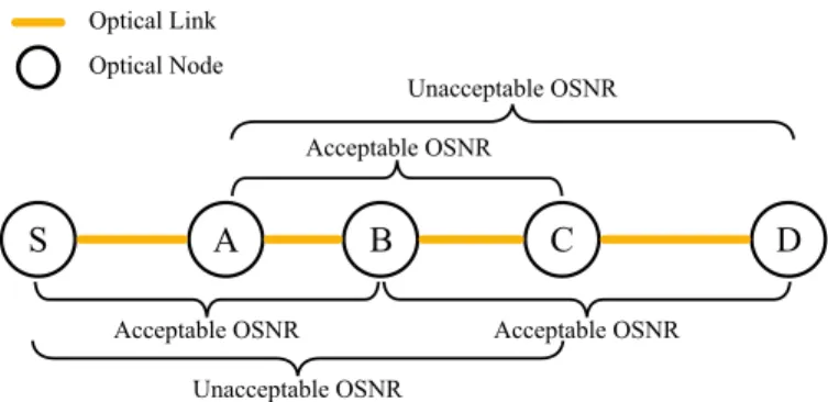
Figure 1, shows an example of connection establishment over an unfeasible optical path. In fact, the unfeasibility of the optical path requires the assignment of regeneration sites at intermediate nodes to get a working channel. In this exam-ple, several combinations for regeneration sites are possible, however, only one combination guarantees a minimum cost. Indeed, the regeneration combinations such as regeneration in
Fig. 1. Example of an unfeasible optical path between node S and D.
node A and C, or regeneration in node A, B and C are possible, but they are not the best solution in terms of cost. Therefore, if the traditional regeneration algorithm is applied, only the node B is assigned to perform the optical regeneration, since it allows exploiting the maximum reach of the transceiver and thus minimizing the number of regenerators used.
B. Power adaptation with optical regeneration
Once the regeneration sites are identified with any regener-ation algorithm (e.g., the traditional regenerregener-ation algorithm or other), the optical path is then decomposed into a set of feasi-ble transparent segments. In [1], we proposed a power adap-tation process to convert the OSNR margins (OSN Rmargin) into optical power attenuation over optical links. To this end, a variable called ”power adaptation coefficient (Cadaptation)” was proposed. This coefficient represents the maximum power attenuation that can be applied for an optical channel between source and destination node. Therefore, in order to perform the power adaptation process over the regenerated optical path, the
power adaptation coefficient Cadaptation should be computed
for every transparent segment.
In this respect, OSNR estimation [1] is performed over each
segment to compute the OSN Rmargin per segment and thus
deduce the applicable Cadaptation coefficient. Note that in
[1], we defined OSN Rmargin as the difference between the
minimum acceptable OSNR (OSN Rreq) and the estimated
one, and Cadaptation as the value of power attenuation that
corresponds to OSN Rmarginfor an optical channel.
Fig. 2. Regeneration assignment using the traditional regeneration algorithm
Let’s consider the example of Figure 2, where an optical regeneration is performed in Node B. In this example the optical path is decomposed into two transparent segments SB
and BD. Therefore, two Cadaptationcoefficients are computed
using the two estimated OSN Rmargin. Then, a channel power
adaptation is applied at the transmitter side of each segment using the computed coefficients.
Note that β ∈ [0, 1] and is used by the control plane to introduce flexibility to the channel power adaptation. β
indicates the portion of OSN Rmarginused per channel
(con-sequently the remaining OSN Rmargin). This offers an
im-portant flexibility for the control plane, where OSN Rmargin
can be shared between different flexible parameters (such as, optical power, modulation format ...). In this paper, we set always β = 1 to maximize the optical power attenuation per channel and because optical power is the only variable parameter considered.
V. ROUTING ALGORITHM WITH REGENERATION
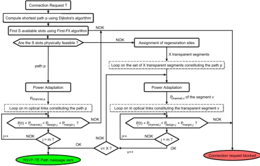
To provision an optical channel in translucent optical net-work, we propose a new path computation algorithm that considers spectral and power resources, physical feasibility of the optical channel and assignment of regenerations, in addition to channel power adaptation. Figure 3 shows a simplified representation of the algorithm.
In this respect, the executed algorithm computes first the shortest path using Dijkstra’s algorithm, for any optical con-nection request of T Gbit/s capacity, between a pair of source and destination nodes. Then, using the first-fit algorithm, it tries to find a group of S available slots of 12.5 GHz width each, that are continuous, contiguous and satisfies the capacity T of the request. For any request, the S slots are computed to get minimum spectrum occupation, supposing a fixed modulation format and baud rate. If no available slots are found the connection request is blocked.
Furthermore, once the S available and successive spectrum slots over the shortest path p are found, the physical feasibility test is performed using the proposed OSNR estimator in [1]. This test checks whether an optical channel can be
established transparently over the path p (i.e., OSN Rest,p>
OSN Rreq,p). If it is the case, then a transparent segment
can be established and just one Cadaptation coefficient, at
the source node, is required to adapt the power of the channel. In contrast, if the path is not physically feasible, one or several optical regenerations should be selected to get a working channel. The number of the regeneration sites depends on the accumulated impairments over the path and on the used regeneration assignment strategy (i.e., minimum number of regenerations or other strategies [17]). As a result, depending on the number of regeneration sites, the path p is decomposed into a set of X transparent segments. Therefore,
an OSN Rmargin is to be computed per segment to get the
applicable Cadaptation value.
After the computation of the Cadaptation coefficients, a
power verification test is performed to ensure that the newly added channel will not cause any saturation problem over the links constituting the path p. This test consists in comparing, for every link of the path p, the aggregate power P (t) (after
adding the power of the new channel Pchannel,ladapted ) with the
Fig. 3. Path computation algorithm with regeneration
corresponds to the optimal optical power per channel over the
link l [1] and Pchannel,ladapted is the optical power of the same
channel after applying the adaptation coefficient.
In the case where no optical regeneration is performed,
the channel power value per link l is Pchannel,ladapted =
Pchannel,lopt /Cadaptation,p. Contrariwise, in the case where optical regeneration is performed, a different Cadaptation coefficient is applied per transparent segment. Therefore,
the channel power value per link l is Pchannel,ladapted =
Pchannel,lopt /Cadaptation,v where v is the index of the trans-parent segment of the path p. Once these tests are done, the signaling process can be triggered over the chosen path. In that case, an extended RSVP-TE P ath message containing power and regeneration information is sent downstream in order to set up the optical channel. If any of these tests fail, the connection request is rejected.
Finally, in each crossed optical node during the signaling process, the power verification test is performed to check if the aggregated power over the outgoing link does not exceed the Pmax,l. Indeed, if connection requests are fre-quent, some signaling process may simultaneously compete for the same optical resources in terms of optical power (race condition). This is why the signaling should avoid any over-provisioning due to the not-yet-updated link database. The same phenomenon (i.e., resources competition) could arise for the optical regeneration modules. Therefore, a last verification test is performed in the regenerating nodes to ensure that the requested regenerator modules are still available.
VI. GMPLSPROTOCOL EXTENSIONS WITH
REGENERATION
In [1], GMPLS protocol extensions were proposed to in-clude routing (Pdesign,l, Pmargin,l, Pchannel,l, and Pl(t),
OSN Rl) and signaling information (i.e., β, Cadaptation) in
transparent networks. However, in the case of translucent net-works, additional extensions are required to take into account the regeneration information and to facilitate the application of the power adaptation process. We recall here that, Pdesign,l represents the total power budget allocated to the link l at
the design phase [1], and Pmargin,l represents the difference
between Pmax,l and Pdesign,l.
In the next sub-sections, we provide the detailed descrip-tions and the encoding formats for the proposed extensions to OSPF-TE and RSVP-TE protocols. Moreover, we present through an example the routing and signaling mechanisms used to exploit them.
A. OSPF-TE
During path computation, optical regeneration sites are usually assigned when the path is not physically feasible. However, this assignment process requires a prior knowledge of the regeneration module sites (i.e., in which node), their capabilities (e.g., acceptable bit rates, modulation formats, etc.) and availability, and lastly their connectivity in the optical nodes (i.e., input/output ports connectivity). In this respect, the RFC standard in [14] proposed several encoding formats to facilitate the dissemination of node information and particularly the regeneration information.
In fact, the OSPF-TE protocol allows the dissemination of two types of information: Node and link information. Usually, these two kinds of information are disseminated using two top-level TLVs: Optical Node Property TLV and Link TLV. The information concerning the optical node can be separated into two categories [18]: node devices (e.g., optical regenerators) and switching capabilities of the node (i.e., connectivity matrix) [19]. Thus, depending on the used control plane implementation and on the switching capability of the ROADMs, the Connectivity Matrix information may be optional. In this work, for simplicity of explanation, we
suppose that the ROADMs support symmetric switching (com-plete port-to-port connectivity) and thus there is no need to ad-vertise their internal connectivity. Therefore, we consider only the information concerning optical devices in the ROADMs. The Optical Node Property TLV includes node properties and signal compatibility constraints. The RFC standards in [20] defined five sub-TLVs to describe these properties and constraints:
1) Resource Block Information, 2) Resource Accessibility,
3) Resource Wavelength Constraints, 4) Resource Block Pool State,
5) Resource Block Shared Access Wavelength Availability. These five sub-TLVs represent respectively: the resource signal constraints and processing capabilities of a node, the structure of the resource pool (i.e., optical regenerator pool) in relation to the switching devices in the node, the input or output wavelength ranges (for wavelength converter devices), the usage state of a resource (i.e., the availability of an optical regenerator), and lastly the accessibility via shared fibers. For simplification reason, we suppose that there are sufficient optical ports and switching modules to handle all wavelength signals. Therefore, only the Resource Block information and the Resource Block Pool State are required and there is no need to advertise the rest of the proposed sub-TLVs.
On one hand, the ResourceBlockInfo sub-TLV allows to list the optical regenerators existing in the optical nodes and enables the description of their processing capabilities (e.g., acceptable bit rates, modulation formats, types of regenerator: 1R, 2R, 3R, etc.). On the other hand, the Resource Block Pool State allows having updated information on regenerators availability in each node after the establishment of any LSP. Hence, to take into account this information, we propose here to add two new sub-TLVs to the Opaque LSA type 1 (”Traffic Engineering LSA”) in the TE Node Attribute TLV (type 6). The encoding of these sub-TLVs is presented in [14].
In this work, we consider only the 3R regeneration (signal amplification, pulse shaping and timing regeneration). There-fore, the first sub-TLV which is called ”RB Set Field” includes the identifiers range for the 3R regeneration modules in every node. Its encoding description is presented in [14]. In our case, we suppose that there is only one range defined per node, and thus the sub-TLV can be encoded on 8 bytes: the first 4 bytes encode the identifier for the start of the range, and the last 4 bytes encode the identifier of the end of the range. Moreover, 4 additional bytes are used to indicate the processing capabilities of the regeneration modules (i.e., to indicate that the regeneration type is 3R). The encoding description is also presented in [14].
The second sub-TLV includes the state of regenerator mod-ules in form of a bitmap to identify whether the requested regenerator module is available or used. This sub-TLV has a variable length since it depends on the number of regeneration modules in the node, but it must be a multiple of 4 bytes (with padding bits if required). Each bit from the sub-TLV indicates the usage status for a regeneration module (0 for available and 1 for used). The sequence of the bitmap is ordered according to the identifiers sequence defined in the ”RB Set Field” (i.e.,
the first bit of the bitmap sub-TLV corresponds to the first regeneration module in the regenerators list of the ”RB Set Field” sub-TLV). These OSPF-TE extensions, in addition to those previously proposed in [1] for link parameters, represent the total information required by any node to execute the path computation algorithm proposed in Section V.
B. RSVP-TE extensions
In [1], we conveyed through RSVP-TE P ath message the required connection information to establish a transparent op-tical channel. This RSVP-TE P ath message include informa-tion on: the central frequency (i.e., channel label), the channel
width, and the Cadaptation,pparameter. These parameters were
valid for an end-to-end connection in a transparent optical network. However, in translucent networks, since optical re-generations are performed, the same information is required for every transparent segment constituting an optical path. Thus, additional information is also required to indicate the need to regenerate the optical signal in intermediate nodes.
1) Label encoding: We propose to use the Flexi-Grid Label
in the Label ERO sub-object as in [21]. The encoding of the Flexi-Grid Label is presented in [22]. This label is used to encode the central frequency and the width (i.e., reserved spectrum bandwidth) of the optical channel. In this work, we suppose that the optical channel keeps the same Flexi-Grid Label all over the path, even if the optical channel is regenerated in intermediate nodes (i.e., we do not take into account the functionality of changing wavelength). This assumption was considered to simplify our routing algorithm and focus on the effect of the optical power control. Therefore, the added labels in the ERO sub-object are the same before and after the identifiers of the regeneration nodes. Once the following extensions are specified under these assumptions, the move to wavelength conversion will be straightforward.
2) Extension for Cadaptation: After the execution of the
path computation algorithm in the ingress node, the required
β and Cadaptation parameters are available to be applied over
the set of segments constituting the regenerated optical path. We propose to create 8 bytes sub-TLVs (2 bytes for type, 2 bytes for length, 2 bytes to encode the value of β and 2 bytes to encode the value of Cadaptation) in the ERO Hop Attributes sub-object (type 35) in the form of Hop Attributes TLVs [23]. Indeed, multiple Hop Attributes TLVs may be added, depending on the number of hops of the optical path (i.e., proportional to the number of nodes in the path). However, the added Hop Attributes TLVs should have the same value per transparent segment; in contrast, they can have different values between the different transparent segments.
3) Regeneration encoding: In the case of non-feasible
optical path, a search for available regeneration modules in intermediate nodes is performed by the path computation algorithm. This is possible thanks to the regeneration module availability information disseminated by the OSPF-TE exten-sions proposed in Section VI-A. Once the optical regeneration modules are chosen through the regeneration algorithm, their identifiers should be conveyed through RSVP-TE P ath mes-sage in order to request their activation in the corresponding nodes.
Therefore, we propose to use the extension ResourceBlock-Info sub-TLV as defined in [15]. In our case, we encode this extension in form of 8 bytes sub-TLVs (1 byte for type, 1 byte for length, 4 bytes to encode the regenerator identifier and 2 bytes padded with zeros to ensure four-octet alignment of the sub-TLV) and put it in the ERO Hop Attributes sub-object (type 35) in form of Hop Attributes TLVs. The number of added ResourceBlockInfo sub-TLVs (which we call hereafter “Regeneration” extension) depends on the number of signal regenerations to be performed over the optical path. These extensions include the identifiers of the assigned regeneration modules, and they are proposed in respect with the recom-mendations of the RFC standard in [15].
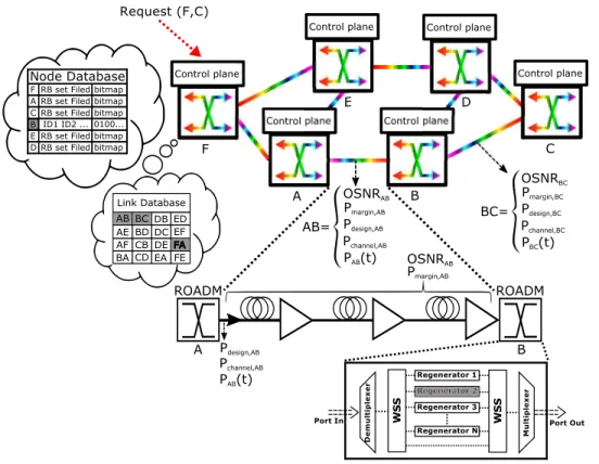
C. Connection establishment example
To understand the provisioning process with power adap-tation in a translucent optical network, we consider here, as an example, an optical network with six optical nodes (i.e., ROADMs). Figure 4 shows the six interconnected nodes (A, B, C, D, E, and F). We assume that optical link design has already been performed for all network links, and that every node database is filled with the existing links (spectrum
bitmap, Pchannel,lopt , Pdesign,l, Pmargin,l, OSN Rl, and Pl(t))
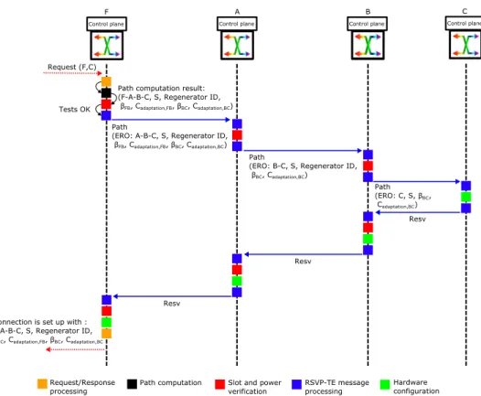
and nodes (RB Set Field, regenerator availability bitmap) information. Moreover, we suppose that a connection request between the ROADMs F and C is sent to Node F. Figure 5 shows the signaling mechanism and the RSVP-TE message flow triggered to establish the optical channel.
In fact, upon receipt of the connection request by Node F, the path computation algorithm is triggered. We assume that, after performing the algorithm, the selected path p is F-A-B-C (shortest path). We assume also that a set of S free available slots is found respecting the continuity and contiguity constraints along this path. We suppose also that the path p is not transparently feasible, because its OSN Rest,F ABC is below the acceptable OSN Rmin, and thus the Node B is assigned to perform signal regeneration. The regeneration in Node B was chosen in respect to the minimum regeneration strategy described in Section IV (i.e., using the traditional regeneration algorithm). In this respect, the optical path is decomposed into two transparent segment F-A-B and
B-C, where OSN Rest,F AB and OSN Rest,BC are higher than
OSN Rmin. In this case, the optical channel is power
adapt-able over the two segments and a Cadaptation parameter is
computed per segment (Cadaptation,F ABand Cadaptation,BC).
Before triggering the RSVP-TE signaling process, Node F performs slot and power verification tests over its outgoing link (i.e., FA). These tests are executed to ensure that optical spectrum resources are still available and no power saturation will occur after adding the new optical channel over link AB
((PF A(t) + Pchannel,F Aopt /Cadaptation,F AB ≤ Pdesign,F A +
Pmargin,F A)).
Once the verification is done, Node F sends an RSVP-TE P ath message to Node A including the information on the selected path p, the S slots used, the identifier of the
regeneration module and the Cadaptation parameters values
(i.e., Cadaptation,F AB and Cadaptation,BC). These parameters
are added in ERO, in form of a list of sub-objects as proposed in Section VI-B and respecting the processing of the ERO in [24]. Figure 5 shows the main parameters of the RSVP-TE message sent to Node A. Upon reception of the P ath message by Node A, the same tests are performed over its outgoing link, AB (it checks that S is still available over the
link AB and that PAB(t) + Pchannel,ABopt /Cadaptation,F A ≤
Pdesign,AB+Pmargin,AB. After this verification is done, Node
A sends a P ath message to Node B after processing the ERO as specified in [24].
Once Node B receives the P ath message from Node A, it detects the ”Regeneration” extension in the ERO sub-object and thus checks whether the requested regenerator is still available or it is already assigned to another connection. If it is available, the slot and power verification tests are performed over its outgoing link BC (it checks that S is still available over
the link BC and that PBC(t)+Pchannel,BCopt /Cadaptation,BC ≤
Pdesign,BC+ Pmargin,BC). At the end of this step, Node B sends a new P ath message to the Node C.
Once the P ath message arrives at the egress Node C, a hardware configuration is performed for its Drop port to receive the optical channel. Moreover, the spectrum bitmap
and the power value of the link BC are updated ((PBC(t) =
PBC(t) + P
opt
channel,BC/Cadaptation,BC)) in its local database, then a Resv message is sent to Node B.
At reception of Resv message by Node B, slot availability and power verification tests are performed again over link BC (this test is not necessary in case local resource reservation was made during downstream signaling). Then, a hardware configuration is made to the requested regenerator and the required power attenuation is applied at the input of the transmitter. Moreover, the spectrum bitmap, regeneration avail-ability bitmap and the power value of link BC are updated in its local database, and a Resv message is sent to Node A.
In turn, Node A executes the same tests over link AB after the receipt of the Resv message and once verification is done, a last Resv message is sent to Node F. These tests are repeated in Node F after the reception of the Resv message. Then, a hardware configuration is performed to its Add port and a power adaptation is applied to the transmitter. Moreover, the spectrum bitmap, regenerator availability bitmap and the power value of link FA (PF A(t) = PF A(t) + Pchannel,F Aopt /Cadaptation,F A) are updated in its local database. Finally, the optical channel is established, and a connection setup confirmation is sent back to the requester (e.g., network operator or client device).
It is important to note that every optical node sends to its neighboring nodes a set of OSPF-TE advertisements. These advertisements are sent to regularly update other nodes with the changes over its outgoing links, typically after the end of a signaling phase. In our case, additional advertisements are sent to update the changes in optical nodes (i.e., to update the availability of optical regeneration modules in each node).
Fig. 4. Network example
VII. SIMULATION AND RESULTS
A. Simulation setup and scenarios
In order to evaluate the proposed power control process in translucent network, we improved our distributed GMPLS-based network simulator to take into account the optical regeneration. The simulator was extended by adding the newly proposed OSPF-TE and RSVP-TE protocol extensions in Section VI. The new routing algorithm and the signaling mechanism are implemented as explained in Section VI-C and V. Moreover, the simulator takes as input a network topology (links, spans, and amplifier types) and it designs its optical links using our design method presented in [25]. Finally, it fills in the OSPF-TE database the essential needed parameters (link
spectrum bitmap, Pchannel,lopt , Pdesign,l, Pmargin,l, OSN Rl,
Pl(t), regenerator availability bitmap, RB set field).
Simulations are performed over the European backbone network [26] (32 optical nodes and 42 optical links) assuming same links parameters (CD, alfa, non-linearity coefficient, etc.) and same amplifiers portfolio as in [1]. However, in order to ease result analysis, only 100 Gbit/s optical channels are established in all scenarios (T = 100 Gbit/s). The filtering penalties resulting from passing through an optical node are 0.05 dB for the 50 GHz channel spacing (four slots of 12.5 GHz) and 0.64 dB for the 37.5 GHz (three slots of 12.5 GHz) [27]. The minimum accepted OSNR at the receiver side, using 0.1 nm noise reference bandwidth, including operational margins, is set to 15 dB for 100 Gbit/s QPSK modulation format with coherent detection and soft decision FEC, what-ever the channel bandwidth (three or four slots of 12.5 GHz). Eight scenarios are considered. We tagged with ”PAPV” the
scenarios using the power control and power margins in their control plane.
• Fixed-grid with optical regeneration (FG R): this sce-nario represents today’s translucent optical networks. For each channel, the spectral occupation is four slots over each transparent segment.
• Fixed-grid with power control, power margins and optical regeneration (FG4S PAPV R): this scenario is the same as FG R but with power control. The power adaptation is applied for minimum acceptable OSNR value. • Flex-grid with optical regeneration (FX R): This scenario
is the same as FG R but with channels that occupy each, only three contiguous slots over every transparent segment.
• Flex-grid with power control, power margins and optical regeneration (FX3S PAPV R): This scenario is the same as FX R but with channel power adaptation.
• Flex-grid with optical regeneration (FX3-4S R): This scenario is a mix of fixed-grid and flex-grid network. The path computation algorithm first tries three slots of 12.5 GHz for the channel setup. If the path is not transparently feasible, the algorithm tries to establish the optical chan-nel using four slots. If still unfeasible, an optical node is assigned for signal regeneration. This regeneration is performed considering a four slots channel.
• Flex-grid with power control, power margins and optical regeneration (FX3-4S PAPV R4): this scenario is the same as FX3-4S R but with power control and with the same regeneration strategy.
Fig. 5. Flow diagram in F, A, B, and C controller during the connection provisioning process.
regeneration (FX3-4S PAPV R3): This scenario is the same as FX3-4S PAPV R4. However, contrarily to the previous scenario (FX3-4S PAPV R4), this regeneration is performed using 3 slots channel.
• Flex-grid with unlimited link power resources and op-tical regeneration (FX3S Full R): This is a benchmark scenario. It is an ideal (unrealistic) scenario which is considered to evaluate the power saturation problem. In this scenario, only three slots channels are established and
the Pmax,l of every link l is supposed unlimited.
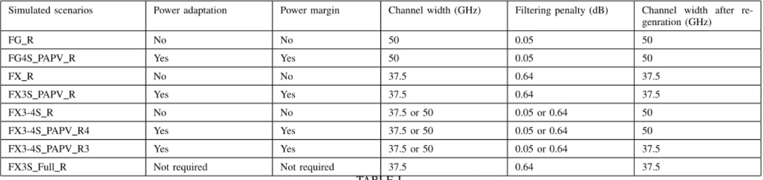
In this work, we consider the same link design as in [1] and the full usable bandwidth of each link is set to 4.8 THz (optical amplifier usable bandwidth) as defined by the ITU-T. Table I summarizes the eight simulated scenarios. The path computation algorithm presented in Section V is modified to enable the simulation of the different scenarios. Depending on the scenario, some tests are activated or deactivated. In the algorithm, only one shortest path is computed for any request between any node pairs (s, d). The connection request is blocked if it cannot pass the set of tests (continuity, contiguity, physical feasibility, and, if needed, power feasibility). Once all the tests are passed, the provisioning process is triggered with a set of channel parameters (path, slots, one or multiple
Cadaptation coefficients, and regenerator identifiers).
B. Simulations configuration
Scenarios were simulated considering a dynamic connection establishment, where optical connections are established and released automatically. Connection requests are dynamically
generated following a Poisson process, where every source-destination pair of each request is randomly chosen among all network nodes according to a uniform distribution. The inter-arrival and holding times for every request follow an exponen-tial distribution with averages of 1/λ, and 1/µ, respectively. The connection holding time 1/µ is fixed to 100 s. The offered network load is obtained by varying 1/λ. The processing time of the packets is considered negligible compared to the propagation delays.
For each network load (i.e., for every value of 1/λ), thirty simulation runs (each run with a different seed) are performed for each of the eight scenarios. Simulation results are collected
after the arrival of 35 × 104 requests in order to ensure that
the network is in a stable state. The results depicted in the following figures are given by averaging the 30 simulation runs of each 1/λ with a confidence interval of 95% (too small to be displayed on the figures). It is important to note that, for every scenario, the same 30 seeds are used in order to exactly simulate the same sequence of optical connection requests. Moreover, for the purpose of the study, the number of 3R regeneration modules per node is not considered as a constraint, and thus no blocking could occur due to the unavailability of regeneration modules.
C. Simulation results
We consider the blocking probability (BP) as an evaluation criterion. It is expressed as the ratio between the number of blocked lightpaths and the number of requested lightpaths. Simulation results for blocking probability are plotted as a function of the total network load defined as N × λ/µ, where
Simulated scenarios Power adaptation Power margin Channel width (GHz) Filtering penalty (dB) Channel width after re-genration (GHz)
FG R No No 50 0.05 50
FG4S PAPV R Yes Yes 50 0.05 50
FX R No No 37.5 0.64 37.5
FX3S PAPV R Yes Yes 37.5 0.64 37.5
FX3-4S R No No 37.5 or 50 0.05 or 0.64 50
FX3-4S PAPV R4 Yes Yes 37.5 or 50 0.05 or 0.64 50
FX3-4S PAPV R3 Yes Yes 37.5 or 50 0.05 or 0.64 37.5
FX3S Full R Not required Not required 37.5 0.64 37.5
TABLE I SIMULATEDSCENARIOS
N = 32 is the number of network nodes and the load is expressed in Erlang. 100 200 300 400 500 600 700 0 0.05 0.1 0.15 0.2 0.25 0.3 0.35
Network load (Erlang)
Blocking probability FG_R FG4S_PAPV_R FX_R FX3S_PAPV_R FX3−4S_R FX3−4S_PAPV_R4 FX3−4S_PAPV_R3 FX3S_Full_R
Fig. 6. Blocking probability versus network load
Figure 6 shows the blocking probability of the eight sce-narios as a function of network load. All scesce-narios with power adaptation (i.e., FG4S PAPV R, FX3S PAPV R, FX3-4S PAPV R4 and FX3-FX3-4S PAPV R3) have lower BP than the other scenarios (i.e., FG R, FX R, and FX3-4S R). We can notice that, FG R, FX R and FX3-4S R scenarios have approximately the same blocking probability. These scenarios are limited by the maximum number of channels designed for optical links or by spectrum unavailability. In fact, the use of flex-grid technology in FX R and FX3-4S R (3 slots channels) reduces the spectrum occupation in optical links. However, even if there is available spectrum slots, blocking may arise from the limited number of channels per link (the number of channels is limited to avoid power saturation since the control plane is not power aware). Accordingly, the blocking reason in FX R is more likely to be due to the limitation of the number of channels, where it is limited to 80 per link. However, in FX3-4S R the blocking occurs due to the spectrum fragmentation and to the limitation of number of channels, since mixing between three and four slots creates unusable spectrum slots. This analysis is confirmed in the next section when blocking reasons are analyzed.
In contrast, the performance of FG4S PAPV R,
FX3S PAPV R, FX3-4S PAPV R4 and FX3-4S PAPV R3
scenarios is impacted differently. In these scenarios, an additional type of blocking may arise which is the power saturation. For example, The FG4S PAPV R scenario shows that the use of power adaptation while keeping in use the fixed-grid technology helps increasing the performance of the network. This increase is achieved through the power saving, allowing the establishment of more than 80 channels per link. However, this gain is directly limited by the spectrum occupation due to the use of four slots channels, promoting in this respect, more blocking due to spectrum unavailability. It can be noticed also that the use of flexible technology with power adaptation offers better performance in terms of blocking probability. Indeed, the FX3S PAPV R, FX3-4S PAPV R and FX3-4S PAPV R3 scenarios undergo less blocking due to the use of 3 slots channels reducing the spectrum occupation in optical links. These scenarios benefit at the same time from the spectrum occupation reduction and from power saving.
Moreover, FX3 PAPV R performs less blocking
probability in comparison with FX3-4S PAPV R4 and
FX3-4S PAPV R3. Indeed, FX3-4S PAPV R4 and
FX3-4S PAPV R3 scenarios, due to the dynamic traffic establishment and to the mixing between three and four slots channels, undergo more severe spectrum fragmentation. Therefore, even if there is sufficient available power, the blocking occurs due to fragmented spectrum of network links. However, FX3-4S PAPV R3 perform less blocking than FX3-4S PAPV R4 since the regenerated channels in FX3-4S PAPV R3 use 3 slots rather than 4 slots, which reduces the spectrum occupation.
Not surprisingly, the benchmark scenario FX3S Full R has the lowest blocking probability and thus the best performance. This was expected since the spectrum unavailability is the only type of blocking that could occur, because link power resources are supposed unlimited. Therefore, the performance difference between the FX3 PAPV R and FX3S Full R is totally due to the effect of link power saturation.
D. Blocking reasons analysis
As in [1], we complete our study with a deep analysis of the blocking reasons in each scenario. To this end, we plotted the reasons of request blocking for each scenario in bar charts. The same blocking reasons presented in [1] are considered (No Spec, No OSNR, No Pow and MXCE). The
No Spec is to represent the blocking due to the unavailability of spectrum slots for a connection request. The No Pow is to represent the blocking due to the unavailability of sufficient power resources. The MXCE is to represent the blocking when the number of channels exceeds the one authorized over optical links (used for scenarios with no power awareness such as FG R). Finally, the No OSNR is to represent the blocking when there is no physically feasible path. However, it cannot exist anymore since optical regeneration can be performed.
The blocking counting method is described as follows: for each connection request and its computed path p, if there are no available continuous and contiguous slots that satisfy the connection request, the blocking reason is counted as No Spec. Contrariwise, in the case the spectrum resources are available; the blocking reason is counted as No Pow or as MXCE depending on the scenario. For FG R, FX R and FX3-4S R scenarios, because no power control is performed, the MXCE blocking reason is considered when the number of channels established over any link exceeds the maximum allowed (i.e., number of channels > 80). For the other scenarios with power awareness, the blocking reason is counted as No Pow. In summary, the priority is given to the No Spec blocking and then to the No Pow and MXCE. This counting method allows avoiding confusion on the No Pow blocking.
To fairly compare all scenarios, we recorded per scenario, the blocking reasons for the 10000 connection requests
gener-ated after the first 35 × 104 requests (same request sequence,
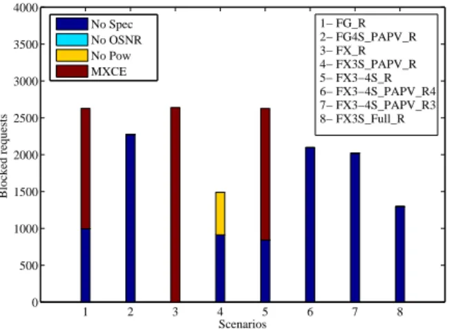
same traffic, and same set of source and destination node pairs for all scenarios). Then, we plotted the number of blocked requests per blocking reason for each of the eight scenarios. Figure 7 shows the number of blocked requests in every scenario at a network load of 600 Erlang (where BP > 0.1).
1 2 3 4 5 6 7 8 0 500 1000 1500 2000 2500 3000 3500 4000 Scenarios Blocked requests No Spec No OSNR No Pow MXCE 1− FG_R 2− FG4S_PAPV_R 3− FX_R 4− FX3S_PAPV_R 5− FX3−4S_R 6− FX3−4S_PAPV_R4 7− FX3−4S_PAPV_R3 8− FX3S_Full_R
Fig. 7. Blocking reasons per simulated scenario
We can notice that at this load (i.e., 600 Erlang) the scenarios without power adaptation, like FG R, FX R and FX34 R, have approximately the same number of blocked requests. In FG R and FX3-4S R, two reasons of blocking are occurring: No Spec and MXCE. However, in FX R scenario, the blocking is only due to MXCE since the use of 3 slots channels reduces the spectrum occupation in every link and thus the spectrum is no more a serious limitation. This shows
the impact of not considering link power resources (high number of blocked requests due to MXCE).
In FG4S PAPV R, FX3-4S PAPV R4 and
FX3-4S PAPV R3 the blocking is due only to No Spec because of two reasons: there is no more limitation to the number of channels per link and the power adaptation process was able to save the required power for the additional channels. However, even if the quantity of saved power is reduced due to the use of 3 slots channels in FX3-4S PAPV R4 and FG3-4S PAPV R3, only No Spec blocking is arising since the mixing of 3 and 4-slot channels increase the fragmentation of optical spectrum.
Contrariwise, the FX3S PAPV R scenario is more im-pacted due to the use of 3 slots channels (which reduces the quantity of saved optical power because of the high filtering penalty). Therefore, the No Pow blocking appears in addition to the No Spec, because link spectrum is less fragmented (i.e., only horizontal fragmentation exists) and thus optical links can be more loaded. Finally, as expected in FX3S Full R, only No Spec blocking is arising because link power resources are supposed unlimited. These results demonstrate that the use of the power adaptation process allows reducing the number of blocked requests and thus increases network capacity and performance.
In summary, the results in Figures 6 and 7, demonstrate that upgrading the network with flex-grid technology without adapting channels power prevents from benefiting of the reduction in spectrum occupation (as it was shown with FX R and FX3-4S R). Therefore, a power aware control plane with power adaptation process helps to increase network capacity and thus to reduce the blocking probability as in FG4S PAPV R. Indeed, when flexibility is associated with power adaptation as in FX3S PAPV R, FX3-4S PAPV R4 and FX3-4S PAPV R3, we can get better network perfor-mance and an important increase in network capacity.
E. Performance in terms of optical regeneration
In terms of regeneration, each scenario performs a smaller or larger number of optical regenerations depending on the regeneration strategy used in the path computation algorithm. Figure 8 shows the number of optical regeneration modules used in the eight scenarios as a function of network load. It can be noticed that the scenarios using 4-slot channels (such as FG R, FG4S PAPV R, FX3-4S R, FX3-4S PAPV R4 and FX3-4S PAPV R3) use less optical regeneration modules compared with the scenarios using only 3 slots channels. Indeed, the 3 slots channels suffers from high filtering penalty and thus long reach channels are more likely to be regenerated in a higher number of intermediate nodes.
Moreover, it can be noticed also on Figure 8 that these scenarios (FG R, FG4S PAPV R, 4S R and FX3-4S PAPV R4 except FX3-FX3-4S PAPV R3) use on average the same number of regenerators. This result indicates that even with the establishment of additional channels in scenarios using the power adaptation process (i.e., FG4S PAPV R and FX3-4S PAPV R4), the number of used regenerators is still the same in comparison with the scenarios without power
100 200 300 400 500 600 700 0 50 100 150 200 250
Network load (Erlang)
Number of used regenerator
FG_R FG4S_PAPV_R FX_R FX3S_PAPV_R FX3−4S_R FX3−4S_PAPV_R4 FX3−4S_PAPV_R3 FX3S_Full_R
Fig. 8. Total number of used regenerators in the network per scenario as a function of network load
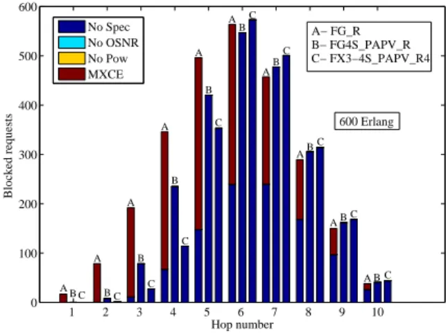
adaptation process. This means that the use of power adap-tation process allows increasing the capacity of the network for the same cost in terms of regeneration. This effect can be explained through Figure 9, where we plotted in bar charts the number of blocked requests per number of hops.
1 2 3 4 5 6 7 8 9 10 0 100 200 300 400 500 600 Hop number Blocked requests No Spec No OSNR No Pow MXCE A− FG_R B− FG4S_PAPV_R C− FX3−4S_PAPV_R4 A B C B C A A B C A B C A B C A B C AB C A C B AB C A B C 600 Erlang
Fig. 9. Blocked requests as a function of the number of hops
Figure 9 shows that the number of long reach requests in FG4S PAPV R and FX3-4S PAPV R4 are more likely to be blocked in comparison with the FG R scenario. In fact, the establishment of more than 80 channels per link increases the spectral occupation in optical links and thus long-reach channels are blocked due to the horizontal fragmentation. At the same time, when mixing 3 and 4-slot channels in FX3-4S PAPV R4 additional blocking could occur due to the vertical fragmentation. This is why the average number of regenerators used in FX3-4S PAPV R4 is slightly smaller than in FG4S PAPV R (long-reach channels are more blocked in FX3-4S PAPV R4 thus less regenerators are used).
However, Figure 8 shows that FX3-4S PAPV R3 sce-nario uses more optical regenerators compared to FX3-4S PAPV R4. In fact, two reasons are behind this result. The first one is because performing optical regeneration with 3
slots channels help to reduce spectrum occupation and thus more optical channels can be established in the network. The second one is because in FX3-4S PAPV R3 the non-feasible channels are regenerated using 3 slots and thus due to the high filtering penalty, more optical regeneration modules can be required along the regenerated path. Finally, it can be remarked that in FX3S PAPV R there is more optical regenerators used on average in comparison to FX R. This is expected since higher number of channels is established when the power adaptation process is used.
VIII. CONCLUSION
In this paper, we addressed the optical power adaptation in translucent optical networks. We extended the GMPLS proto-col suite in order to support optical regeneration and power adaptation process. In this respect, a path computation algo-rithm with new protocols extensions and signaling mechanism were proposed to RSVP-TE and OSPF-TE protocols. These extensions allow taking into account the optical regenerator availability and assignment, and performing channel power adaptation. Moreover, the migration from fixed-grid to flex-grid networks was studied with dynamic traffic patterns, where it was demonstrated that the power saturation problem can arise independently from traffic pattern (i.e., incremental [1] or dynamic).
Simulation results showed that upgrading fixed-grid network with flexible technology without adapting channel power pre-vents benefiting from spectrum saving and increases network cost. Moreover, it showed that regeneration assignment strat-egy used in the path computation algorithm can also impact the performance of the network and its cost. Finally, the usage of appropriate regeneration algorithms by network operators allows significant increase in their network capacity [28].
It is important to note that, this work on power control is not meant to be limited to GMPLS control plane. The same principle of optical power control and optimized regeneration placement can be implemented on SDN controllers via other suitable protocols. This can be realized by simply adding the same proposed parameters in its corresponding protocol exten-sions for the considered control plane. Moreover, including all flexibility parameters (such as, modulation format, baud rate, and others) in the routing algorithm would improve the usage of network resources. This increases respectively its capacity and could even increase the optical power issue. Therefore, proposing better routing algorithm is left for future works.
REFERENCES
[1] M. Kanj, E. L. Rouzic, J. Meuric, B. Cousin, and D. Amar, “Optical power control in gmpls control plane,” IEEE/OSA Journal of Optical Communications and Networking, vol. 8, no. 8, pp. 553–568, Aug 2016. [2] R. Martinez, R. Casellas, R. Munoz, T. Tsuritani, and T. Otani, “Ex-perimental GMPLS routing for dynamic provisioning in translucent wavelength switched optical networks,” in 2009 Conference on Optical Fiber Communication, March 2009, pp. 1–3.
[3] R. Martinez, R. Casellas, R. Munoz, and T. Tsuritani, “Experimen-tal translucent-oriented routing for dynamic lightpath provisioning in gmpls-enabled wavelength switched optical networks,” Journal of Light-wave Technology, vol. 28, no. 8, pp. 1241–1255, April 2010.
[4] N. Sambo, A. Giorgetti, F. Cugini, N. Andriolli, L. Valcarenghi, and P. Castoldi, “Accounting for Shared Regenerators in GMPLS-Controlled Translucent Optical Networks,” Journal of Lightwave Tech-nology, vol. 27, no. 19, pp. 4338–4347, Oct 2009.
[5] H. Guo, T. Tsuritani, S. Okamoto, and T. Otani, “Demonstration of GMPLS-controlled inter-domain transparent optical networks,” in 2008 34th European Conference on Optical Communication, Sept 2008, pp. 1–2.
[6] R. Martinez, C. Pinart, F. Cugini, N. Andriolli, L. Valcarenghi, P. Cas-toldi, L. Wosinska, J. Comellas, and G. Junyent, “Challenges and requirements for introducing impairment-awareness into the manage-ment and control planes of ASON/GMPLS WDM networks,” IEEE Communications Magazine, vol. 44, no. 12, pp. 76–85, Dec 2006. [7] Y. Lee, G. Bernstein, and W. Imajuku, “Framework for GMPLS and PCE
Control of Wavelength Switched Optical Networks (WSON),” Internet Requests for Comments, RFC Editor, RFC 6163, April 2011. [8] F. Cugini, N. Sambo, A. Giorgetti, L. . Valcarenghi, P. Castoldi, E. L.
Rouzic, and J. Poirrier, “GMPLS extensions to Encompass Shared Regenerators in Transparent Optical Networks,” in 33rd European Conference and Exhibition of Optical Communication, Sept 2007, pp. 1–2.
[9] N. Sambo, F. Cugini, N. Andriolli, A. Giorgetti, L. Valcarenghi, and P. Castoldi, “Lightweight RSVP-TE extensions to account for Shared Regenerators in Translucent Optical Networks,” in 2007 Photonics in Switching, Aug 2007, pp. 35–36.
[10] N. Sambo, N. Andriolli, A. Giorgetti, F. Cugini, L. Valcarenghi, and P. Castoldi, “Distributing Shared Regenerator Information in GMPLS-Controlled Translucent Networks,” IEEE Communications Let-ters, vol. 12, no. 6, pp. 462–464, June 2008.
[11] D. J. Ives, P. Bayvel, and S. J. Savory, “Adapting transmitter power and modulation format to improve optical network performance utilizing the gaussian noise model of nonlinear impairments,” Journal of Lightwave Technology, vol. 32, no. 21, pp. 4087–4096, Nov 2014.
[12] A. Nag, M. Tornatore, and B. Mukherjee, “Power management in mixed line rate optical networks,” in Integrated Photonics Research, Silicon and Nanophotonics and Photonics in Switching. Optical Society of America, 2010, p. PTuB4.
[13] D. J. Ives, P. Bayvel, and S. J. Savory, “Assessment of options for utilizing SNR margin to increase network data throughput,” in Optical Fiber Communication Conference. Optical Society of America, 2015, pp. M2I–3.
[14] G. Bernstein, Y. Lee, D. Li, W. Imajuku, and J. Han, “Routing and Wavelength Assignment Information Encoding for Wavelength Switched Optical Networks,” Internet Requests for Comments, RFC Editor, RFC 7581, June 2015.
[15] G. Bernstein, S. Xu, Y. Lee, G. Martinelli, and H. Harai, “Signaling extensions for wavelength switched optical networks,” Internet Requests for Comments, RFC Editor, RFC 7689, November 2015.
[16] Y. Lee, G. Bernstein, D. Li, and W. Imajuku, “Routing and wave-length assignment information model for wavewave-length switched optical networks,” Internet Requests for Comments, RFC Editor, RFC 7446, February 2015.
[17] D. C. Rider, J. C. Slezak, A. V. W. Smith, and A. Lucent, Regenerators placement mechanism for wavelength switched optical networks. Erteilung, Mar. 2002. [Online]. Available: http://www.google.ch/patents/US8571415
[18] F. Zhang, Y. Lee, J. Han, G. Bernstein, and Y. Xu, “OSPF-TE Exten-sions for General Network Element Constraints,” Internet Requests for Comments, RFC Editor, RFC 7580, June 2015.
[19] G. Bernstein, Y. Lee, D. Li, W. Imajuku, and J. Han, “General Net-work Element Constraint Encoding for GMPLS-Controlled NetNet-works,” Internet Requests for Comments, RFC Editor, RFC 7579, June 2015. [20] Y. Lee and G. Bernstein, “GMPLS OSPF Enhancement for Signal
and Network Element Compatibility for Wavelength Switched Optical Networks,” Internet Requests for Comments, RFC Editor, RFC 7688, November 2015.
[21] L. Berger, “Generalized Multi-Protocol Label Switching (GMPLS) Sig-naling Resource ReserVation Protocol-Traffic Engineering (RSVP-TE) Extensions,” Internet Requests for Comments, RFC Editor, RFC 3473, January 2003.
[22] A. Farrel, D. King, Y. Li, and F. Zhang, “Generalized Labels for the Flexi-Grid in Lambda Switch Capable (LSC) Label Switching Routers,” Internet Requests for Comments, RFC Editor, RFC 7699, November 2015.
[23] C. Margaria, G. Martinelli, S. Balls, and B. Wright, “Label Switched Path (LSP) Attribute in the Explicit Route Object (ERO),” Internet Requests for Comments, RFC Editor, RFC 7570, July 2015.
[24] D. Awduche, L. Berger, D. Gan, T. Li, V. Srinivasan, and G. Swallow, “RSVP-TE: Extensions to RSVP for LSP Tunnels,” Internet Requests for Comments, RFC Editor, RFC 3209, December 2001.
[25] M. Kanj, E. L. Rouzic, D. Amar, J. L. Auge, B. Cousin, and N. Brochier, “Optical power control to efficiently handle flex-grid spectrum gain over existing fixed-grid network infrastructures,” in 2016 International Conference on Computing, Networking and Communications (ICNC), Feb 2016, pp. 1–7.
[26] M. Kanj, “Intelligent supervision of flexible optical networks,” Ph.D. dissertation, Universit Rennes 1, 2016.
[27] R. Casellas, R. Muoz, R. Martnez, R. Vilalta, L. Liu, T. Tsuritani, I. Morita, V. Lpez, O. G. de Dios, and J. P. Fernndez-Palacios, “SDN orchestration of OpenFlow and GMPLS flexi-grid networks with a stateful hierarchical PCE [invited],” IEEE/OSA Journal of Optical Communications and Networking, vol. 7, no. 1, pp. A106–A117, Jan 2015.
[28] M. Kanj, E. L. Rouzic, and B. Cousin, “Power-aware regeneration algorithm in flex-grid networks,” in 2017 43th European Conference on Optical Communication, Sept 2017, pp. 1–3.
Matthieu Kanj received an engineering degree from Superior National School of Computer and Applied Mathematics of Grenoble (ENSIMAG), France, in 2012, and a Ph.D. degree in computer science from Rennes 1 University, France, in 2016. He is currently a research engineer at b<>com. His research inter-ests concern computer and optical network architec-ture, Flex-Grid technology, GMPLS protocol suite for optical networking, Mobile networks, radio com-munications/architectures and Internet-of-things.
Esther Le Rouzic received a telecommunication degree from Telecom Bretagne, France, an M.Sc. degree from the University College London, U.K., in 1996, and a Ph.D. degree in electronics and communications from Telecom Paris, Paris, France, in 1999. She joined Orange Labs (previously France Telecom R&D), Lannion, France, in 2000, where she has been working on optical networks.
Julien Meuric graduated from the French engi-neering school ”Ecole Nationale Suprieure des Sci-ences Appliques et de Technologie” (ENSSAT). He joined Orange Labs (previously France Telecom R&D), Lannion, France, in 2004, where he has worked on metropolitan and optical core networks. As standardization senior manager, he is involved in standardization around GMPLS control protocols in corresponding IETF working groups. He also acts in IETF as co-chairman of the Path Computation Element (PCE) working group.
Bernard Cousin is a Professor of Computer Science at the University of Rennes 1, in France. Bernard Cousin received, in 1987, his Ph.D. degree in com-puter science from the University of Paris 6. He is a member of IRISA (a CNRS-University joint research laboratory located at Rennes in France). He has co-authored 150+ papers published in international journals and conferences. His research interests in-clude next generation Internet, green networking, all-optical networks, wireless networks.