HAL Id: hal-00908803
https://hal.inria.fr/hal-00908803
Submitted on 25 Nov 2013
HAL is a multi-disciplinary open access
archive for the deposit and dissemination of
sci-entific research documents, whether they are
pub-lished or not. The documents may come from
teaching and research institutions in France or
abroad, or from public or private research centers.
L’archive ouverte pluridisciplinaire HAL, est
destinée au dépôt et à la diffusion de documents
scientifiques de niveau recherche, publiés ou non,
émanant des établissements d’enseignement et de
recherche français ou étrangers, des laboratoires
publics ou privés.
The TeleKyb Framework for a Modular and Extendible
ROS-based Quadrotor Control
Voker Grabe, Martin Riedel, Heinrich H Bülthoff, Paolo Robuffo Giordano,
Antonio Franchi
To cite this version:
Voker Grabe, Martin Riedel, Heinrich H Bülthoff, Paolo Robuffo Giordano, Antonio Franchi. The
TeleKyb Framework for a Modular and Extendible ROS-based Quadrotor Control. European
Confer-ence on Mobile Robots, ECMR 2013, Sep 2013, Barcelona, Catalonia, Spain. �hal-00908803�
Preprint version 2013 6th European Conference on Mobile Robots, Barcelona, Catalonia, Spain
The TeleKyb Framework for a
Modular and Extendible ROS-based Quadrotor Control
Volker Grabe, Martin Riedel, Heinrich H. B¨ulthoff, Paolo Robuffo Giordano, Antonio Franchi
Abstract— The free and open source Tele-Operation Platform of the MPI for Biological Cybernetics (TeleKyb) is an end-to-end software framework for the development of bilateral teleoperation systems between human interfaces (e.g., haptic force feedback devices or gamepads) and groups of quadrotor Unmanned Aerial Vehicles (UAVs). Among drivers for devices and robots from various hardware manufactures, TeleKyb provides a high-level closed-loop robotic controller for mobile robots that can be extended dynamically with modules for state estimation, trajectory planning, processing, and tracking. Since all internal communication is based on the Robot Operating System (ROS), TeleKyb can be easily extended to meet future needs. The capabilities of the overall framework are demon-strated in both an experimental validation of the controller for an individual quadrotor and a complex experimental setup in-volving bilateral human-robot interaction and shared formation control of multiple UAVs.
I. INTRODUCTION
The challenges inherent to software development for a robotic platform have constantly changed over the last decade. Initially, the program code for robotic platforms comprising a certain set of sensors, actuators and controllers were developed solely for a specific hardware architecture, making the reuse of software complicated and thus often impractical. Recently, the design of robotic platforms has moved to setups that are more modular and allow for a sim-plified integration or exchange of individual hardware com-ponents [1]. Therefore the underlying software architectures that operate these robots required a fundamental paradigm shift consisting of, e.g., the introduction of increasing levels of abstractions.
Since then, robotic middleware solutions migrated to a thin-design paradigm that supports the development of mod-ular components and increases the ability to reuse existing code. Several frameworks follow this new paradigm (see, e.g., [2], [3]) with the Robot Operating System (ROS) being one of the most popular [4]. Since its release in 2007, several hundred packages have been published.
Despite the clear benefits that ROS introduced to the robotic community, the concept of ROS is not particularly new, but it is actually comparable to existing solutions such
V. Grabe, M. Riedel, H. H. B¨ulthoff and A. Franchi are with the Max Planck Institute for Biological Cybernetics, Spemannstraße 38, 72076 T¨ubingen, Germany. E-Mail: {volker.grabe, martin.riedel, hhb,
antonio.franchi}@tuebingen.mpg.de.
P. Robuffo Giordano is with the CNRS at IRISA, Campus de Beaulieu, 35042 Rennes Cedex, [email protected].
V. Grabe is additionally with the University of Zurich, Andreasstr. 15, 7050 Zurich, Switzerland. H. H. B¨ulthoff is additionally with the Department of Brain and Cognitive Engineering, Korea University, Seoul, 136-713 Korea.
as, e.g., the Inter Process Communication (IPC) library [5]. That is, ROS provides mainly a communication interface between independent pieces of a framework together with a platform to share released code. In order to implement their algorithms on a particular robotic platform, roboticists are still forced to develop the appropriate drivers and controllers and to link them into a reliable framework. While drivers for several hardware components have been gratefully shared by other scientists through ROS, the development of an appropriate control framework still remains a challenging and time-consuming task, for example in the popular research field on Unmanned Aerial Vehicles (UAVs).
Over the last years, use of small quadrotor UAV platforms has gained immense popularity in the robotics community due to their small costs, robustness, flexibility, and hovering capabilities. However, at the best of our knowledge, only few research labs publicly released their complete quadrotor control frameworks. Moreover, each framework is typically limited to a particular chain constituted by a specific control device, a specific state estimator, and specific flight con-troller and vehicle driver. For the commercially available AR.Drone1, a position controller has been released [6]: this is based on the velocity controller provided by the manufacturer. However, this solution is highly specific to quadrotor platforms that are endowed with an on-board velocity sensor and accept velocity commands. Similarly, a control framework restricted to quadrotors from Ascending Technologies2 has been published [7]. Both frameworks
include an estimator of the the quadrotor state that exploits a low-frequency visual-based pose estimation together with acceleration and angular velocity readings from the on-board inertial measurement unit (IMU).
However, both systems lack the support for other hardware platforms, are limited to a single mode of operation, and do not support the simultaneous control of a swarm of quadrotors for cooperative operations. Furthermore, they have not been designed to facilitate input modalities other than the specification of predefined waypoints and thus do not allow for a bilateral control in telepresence situations using, e.g., force feedback devices as in [8].
In order to compensate for this lack of basic features, in this paper we propose a complete modular control frame-work for a generic quadrotor UAV based on ROS. By providing structured interfaces, the user can dynamically extend the framework, while still maintaining basic security
1http://ardrone2.parrot.com
mechanisms, like state supervision and fall-back modules. The full control chain released to the public is completely extendable and already includes support for various input devices, multiple heterogeneous UAVs, and different state estimators.
The remainder of this paper is structured as follows. The main components and interfaces of the proposed framework are discussed in Sec. II. In Section III, all components involved with the actual control of the quadrotor UAVs are discussed in more detail and we summarize the modules included in the open source code release of this project in Sec. IV. Finally, we present and discuss our experimental evaluation in Sec. V and VI before the paper is concluded in Sec. VII.
II. MAJORCOMPONENTS OFTELEKYB
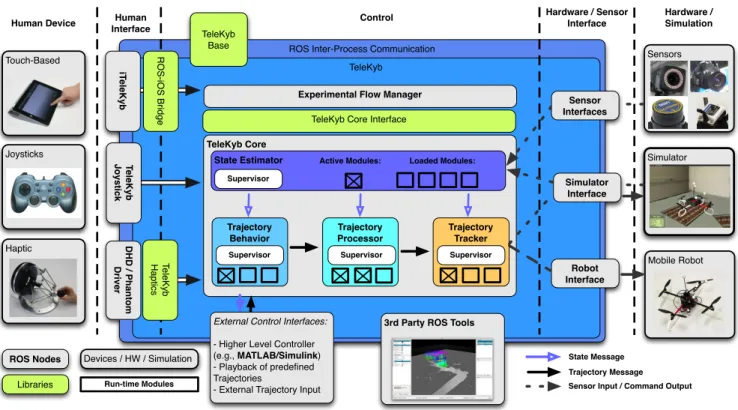
TeleKyb is an extensive software framework consisting of more than 50 ROS packages for the end-to-end solution of quadrotor based setups. This includes a human interface layer for direct modes of interaction with the human op-erator, a control layer for motion planning and actuation of the quadrotor, and a hardware interface layer used to interface the particular quadrotor hardware. In the following, we describe the main components of TeleKyb as illustrated in Fig. 1.
A. Human Interface
Human input appliances that feed back haptic cues to the operator have become a popular field of research in the human-robot interaction community [9]. Since the variety of haptic-device manufacturers all use different SDKs for their hardware, TeleKyb Haptics provides a unique interface for the common types of haptic devices and thus implements the haptic control algorithm using standardized methods. These methods are then implemented by the specific hardware driver. Currently, TeleKyb supports all device classes of Force Dimension3.
Human input devices which do not provide haptic feed-back, such as common joysticks and gamepads, can be directly used with TeleKyb if they are natively supported by the operating system.
B. TeleKyb Base
TeleKyb Base provides a variety of helper classes which
are aimed to support the roboticists in the development of control algorithms. Among an improved memory manage-ment and multiple conversion functions for various purposes, the ROS parameter system has been greatly extended.
TeleKyb Options provide a mechanism to expose
parame-ters of any node to external entities which can be updated at run-time. Thus, they combine the capabilities of the default ROS parameters and the ROS dynamic reconfigure4package.
However, as opposed to the original ROS parameters, the
Option class supports optional bounds, read-only options,
handles the correct namespace automatically and is not
3http://forcedimension.com/
4http://ros.org/wiki/dynamic reconfigure
restricted to the native datatypes integer, double, and string. For example, it is possible to handle matrices or vectors as parameters.
C. TeleKyb Core
TeleKyb Coreis a high-level closed-loop robotic controller
composed of four main elements with distinct functionali-ties. The State Estimator estimates the current pose of the robot, theTrajectory Behaviorunit computes the next desired position and velocity, the Trajectory Processor implements additional functionality such as obstacle avoidance, and the
Trajectory Tracker computes the next commands which are
then sent to the robot as explained in more detail in Sec. III. D. ROS–Simulink Bridge
MATLAB/Simulink is a popular tool for the simulation and control of dynamic systems, including robots. However, depending on the release, it links against older versions of certain libraries (e.g., boost) than those present on current unix operating systems and which are therefore used when TeleKyb is built. To the best of our knowledge, all the currently available ROS–MATLAB interfaces provide com-munication between MATLAB and other ROS nodes via relatively slow network transmission rather than a native integration.
To overcome this limitation, we setup an environment to compile ROS against specific MATLAB versions and oper-ating systems. The resulting shared libraries are then linked against MATLAB S-functions to implement the Simulink side of the ROS interface. Thanks to this setup, generic S-function publisher and subscriber blocks use the native ROS communication stack for the exchange of message with other nodes. We have recently joined efforts with MathWorks to integrate this ROS interface into coming versions of MATLAB.
Within TeleKyb, this allows for the use of MAT-LAB/Simulink on top of the TeleKyb Core and Simulink can be utilized for the implementation and evaluation of higher-level algorithms or alternative controllers. Similarly, the ROS–MATLAB bridge can be utilized for the integration of human input devices with existing ROS drivers into MAT-LAB programs. Our bridge has already been successfully applied in various setups [10], [11].
E. Obstacle Provider
Applications for mobile robots often include the neces-sity to detect and dynamically react to obstacles in the environment. For this purpose, TeleKyb uses an Obstacle
Providerwhich maintains a list of obstacle modules. TeleKyb
provides modules for the definition of constant obstacles, fixed geometric structures, and dynamically moving obsta-cles provided from either on-board observations or external sources such as motion tracking systems.
F. Robot Interface
TeleKyb is in general not restricted to be only used with quadrotors UAVs, but can rather be employed with a
Touch-Based
Joysticks
Haptic
ROS Inter-Process Communication TeleKyb Robot Interface Mobile Robot Simulator Sensors Human Device Hardware / Simulation Hardware / Sensor Interface Control
External Control Interfaces: - Higher Level Controller (e.g., MATLAB/Simulink) - Playback of predefined Trajectories
- External Trajectory Input
3rd Party ROS Tools TeleKyb Core
Experimental Flow Manager
State Estimator Trajectory Behavior Trajectory Tracker TeleKyb Base Trajectory Processor Human Interface Simulator Interface Sensor Interfaces D H D / Ph a n to m Driver Te le Kyb H a p tics R O S-i O S Bri d g e Te le K y b J o y s ti c k
TeleKyb Core Interface
iT
eleKyb
Supervisor
Supervisor Supervisor Supervisor
Loaded Modules:
ROS Nodes
Libraries
Devices / HW / Simulation State Message Trajectory Message Sensor Input / Command Output Run-time Modules
Active Modules:
Fig. 1: High-level overview of major TeleKyb components. TeleKyb bridges the gap between user interfaces and robot hardware by introducing the TeleKyb interface layer.
wide variety of mobile robots since the implementation of hardware interfaces is strictly separated from the underlying algorithms. For each vehicle, suitable controller modules (see Sec. III) have to be provided together with an implementation of the Robot interface. This interface allows for both high frequency messages (such as control commands and sensor data) and asynchronous communication that can be used, e.g., to update controller gains or trigger an emergency procedure. Incoming data from the robot can be examined to react automatically on certain events such as low battery or detection of unexpected changes in some variables of the system. All communication can be exposed to ROS topics for monitoring or visualization purposes.
G. Simulator Interface
Robotic simulators provide both the simulation of a partic-ular robotic hardware and the environment surrounding the robot. For the use of TeleKyb with a simulation, both a robot interface and a state estimation module (as introduced in Sec III-A) have to be provided. Currently, TeleKyb provides full supports for SwarmSimX [12], while an integration of v-rep5 is under active development.
III. TRAJECTORYPROCESSING ANDCONTROL
In this section, the details of the TeleKyb Core and the different stages of our universal quadrotor controller are explained.
5http://coppeliarobotics.com
A. State Estimation
TheState Estimatorconsists of aSupervisorand a number
of run-time loadable modules that provide the actual state estimation functionality. While theSupervisor is responsible for loading, unloading, and transition between the individual estimator modules, the currently active module generates a standardized state message (p,˙p, q, ω), where p, ˙p, q, ω denote the position, velocity, orientation and angular velocity of the robot, respectively. This message is then distributed to the other parts of the controller within theTeleKyb Core. The active state estimation module can be changed at run-time, which allows for a safe fall-back state estimator module once another, e.g. vision based, estimator becomes too noisy or returns unreliable data. Also, estimators based on different sensors can be used for different behaviors of the flight, e.g., during the take-off or cruse phase, as described in Sec. III-B. For external optical tracking systems, TeleKyb supports all systems that implement the free and open VRPN standard. In particular, this is the case with both the Vicon6 and
the OptiTrack7 tracking systems. Since the state message
requires the additional knowledge of the linear and angular velocities ˙p and ω, they are numerically computed from the pose p and the orientation q as obtained from the tracking systems using the signal filtering libraries provided with TeleKyb.
6http://vicon.com
T ra je c to ry Behavior Tra je c to ry Tr a c k e r Position Error Checker Trajectory Processor State Message Trajectory Message Obstacle Points Behavior Change Velocity Saturation Obstacle Avoidance
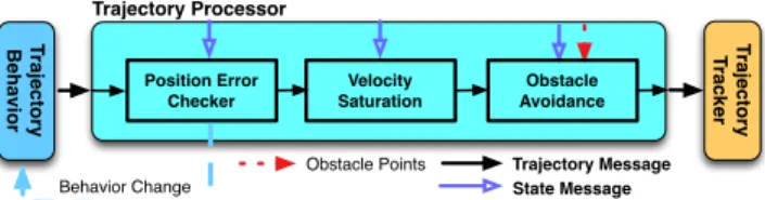
Fig. 2: Priority list of Trajectory Processor modules as they dy-namically alter the current trajectory message before it is executed.
B. The Behavior System
The Trajectory Behavior system is one of the most
pow-erful components of the control framework and contributes largely to its flexibility. Similar to the State Estimator, a
Supervisor manages individual modules which provide the
actual functionality, in the following referred to asBehaviors. The active behavior is responsible for the generation of a trajectory message every time a new state was made available by the State Estimator.
Behaviors dynamically generate trajectories for any given task during a robotic experiment. While many default behav-iors such as Take-Off, Hover, Fly-To, Trajectory Following, Human Controland Land are already included with TeleKyb, the user can easily add new behaviors by implementing a provided interface. Consequently, theSupervisor can switch between individual behaviors in order to describe higher-level motions such as Take-Off → Brake → Hover → Land. Therefore, the behavior system is equivalent to a finite-state machine with exactly one active behavior at any time and well-defined rules for the transitions. To ensure safe transitions, a type is assigned to each behavior and transitions are only allowed between behaviors of certain types, e.g., Ground → Take-Off, Air → Air, . . . . Additionally, they can be linked by defining a pointer to the next behavior. This behavior will then become active once the previous one terminates. This termination criterion can be either defined within each behavior or triggered by user input. A behavior without a follow-up element will be automatically followed by the Brake behavior which in turn will be followed by the Hover behavior until a new behavior is requested.
Since behaviors can be chained and each sequence forms a more complex behavior again, this simple design princi-ple allows to accommodate a wide range of experimental conditions.
C. The Trajectory Processor
TheTrajectory Processor maintains multiple modules able
to dynamically alter the trajectory message generated from the active Behavior before it is passed on to the Trajectory
Tracker. Several modules can be active at the same time and
are applied to each trajectory message in sequential order, as shown in Fig. 2.
Generally, trajectory processor modules can either alter the trajectory message directly, e.g., to implement obstacle avoidance, or influence the system in a more indirect way by initiating aBehaviorswitch, e.g., to brake if some unexpected conditions were detected. Furthermore, modules can observe
and interact with other components of the TeleKyb Core
through the option system and, e.g., change the gains of the controller to less aggressive settings.
D. The Trajectory Tracker
The Trajectory Tracker computes the needed robot com-mands from both the current state and trajectory message.
The control design is based on the natural decoupling between attitude and linear dynamics (the former is indepen-dent from the latter). The design is then made in two steps in a classical cascade fashion: first, a fast attitude controller enforces tracking of a desired attitude unit quaternion qdes(t)
to the current quadrotor orientation q(t) by exploiting the full actuated rotational dynamics for quadrotor UAVs (three available torque inputs). Then, a slower position controller generates the attitude set-point qdes(t) needed to properly
re-orient the direction of the fourth input (thrust) so as to obtain the desired translational motion, i.e., for eventually letting the position p(t) to track a desired reference pdes(t). Compared
to other control designs (e.g, feedback linearization), this solution can result in a less performant transient behavior but benefits from a higher robustness w.r.t. disturbances, parametric and modeling uncertainties thanks to the afore-mentioned dynamical separation.
E. The on-board Low-Level Controller
While TeleKyb supports UAVs from Ascending Technolo-gies, KMel Robotics8, and MikroKopter9, the integration of
quadrotors from MikroKopter is currently most advanced due the possibility to implement the on-board low-level controller manually.
The on-board low-level controller is in charge of letting the quadrotor orientation q(t) track a desired reference qdes(t).
As classically done, this is achieved by neglecting the couplings among the three body axes, and by treating each individual rotation (roll, pitch, yaw) as a separate channel modeled as a double integrator with input the correspondent body torque. The adopted controller is then a simple PID with saturated integral term in order to prevent wind-up issues. Readings from the on-board gyros are exploited as velocity feedback, while a complementary filter provides es-timates of the UAV attitude by fusing together accelerometer and gyro readings from the IMU.
F. TeleKyb Core Interface
TheTeleKyb Core Interfaceallows to dynamically load and
configure theEstimation,Behavior,ProcessingandTracking
modules. Furthermore, it provides automatic callbacks to track certain events such as a behavior transition in the
Trajectory Behavior stage.
G. Experimental Flow Manager
The Experimental Flow Manager controls the flow of an
entire experiment consisting of one or moreTeleKyb Cores, one for each robot. For this purpose, it can be launched from
8http://kmelrobotics.com
9http://mikrokopter.de
TABLE I: Hardware supported with TeleKyb download Input Devices Gamepads, Devices from Force-Dimension Tracking Systems Vicon, OptiTrack, and others with VRPN support
UAVs MikroKopter (with provided extended low-level
firmware), AscTec UAVs (beta version only)
Fig. 3: The quadrotors used for the evaluation: Nano+ from kmel (left) and a MK-Quadro from MikroKopter (right).
anywhere in the network. Using theTeleKyb Core Interface,
the TeleKyb Cores can be configured and manipulated
on-line, e.g., to specify when Behaviors become active and how they are configured. In this role, theExperimental Flow
Managerscan be used to trigger events on theTeleKyb Cores,
for example when requested by input devices connected to the network. Additionally, the Experimental Flow Manager
can be informed by aTeleKyb Coreto react on events such as the termination of aBehavior. This concept was also used to implement control through a touch-based hand-held device.
IV. SOURCECODERELEASE
We released all major components of TeleKyb under the BSD license. A current version of TeleKyb can be obtained from
https://svn.tuebingen.mpg.de/kyb-robotics/
TeleKyb/trunk. Table I lists the hardware drivers
provided with TeleKyb. A documentation including quick start instructions has been integrated into the ROS Wiki at
http://ros.org/wiki/telekyb. For license reasons, we
were not allowed to provide the communication interface for the vehicles from KMel Robotics. Please note that, according to the BSD license, the software is provided ’as is’ and we cannot be hold responsible for any damage or harm caused by the use of our software.
V. EXPERIMENTS
In order to both evaluate the accuracy of the controller included with TeleKyb, and the ability to design complex ex-periments, we conducted two individual sets of experiments described in Sec. V-A and Sec. V-B, respectively.
As for the hardware setup, we used two different types of quadrotors, a Nano+ from KMel Robotics with a diameter of0.19 m and a weight of 0.230 kg, and a MK-Quadro from MikroKopter with a diameter of 0.50 m and a weight of 1.050 kg. Both are shown in Fig. 3.
The state of the robot was retrieved via an external motion capture system at the frequency of 120 Hz and sub-millimeter precision. The desired roll, pitch, yaw-rate, and thrust commands computed by the controller are sent to attitude controller implemented on the micro controller by means of a wireless serial communication.
Both UAVs were flown using the same controller gains. A mass estimator included in TeleKyb estimated the actual quadrotor mass starting from a rough initial estimate: this allowed to autonomously compensate for the different char-acteristics of the two vehicles. The velocity was restricted to 1.0 m/s through configurable options for safety reasons. Likewise, the maximum tilt angle was limited to 20◦, thus
also limiting the maximum achievable linear acceleration. A. Experiment for Evaluation of the Controller
The first set of experiments was designed to evaluate the TeleKyb controller. In an initial setup, we aimed to test
theTrajectory Tracker which provides appropriate orientation
(i.e., attitude) and thrust commands to the UAVs given the desired positions, velocities, and accelerations at each control iteration. Both UAVs were flown along the same trajectory (a ‘eight’ shape) with a given velocity profile defined prior to the experiment. One loop along whole curve lasted 10 s with a peak velocity of0.65 m/s.
In a second experiment, the whole controller chain, includ-ing a Fly-To Behavior that computes the trajectory towards a defined target on-line, was investigated. Both UAVs were commanded to fly to a target location approximately 2 m from the hovering UAV and stop there.
B. Experiment with a Swarm and Human In-the-loop To demonstrate the capabilities of the TeleKyb framework with respect to more complex scenarios including presence of multiple UAVs, obstacle avoidance, human-robot interaction and haptic control, we designed an experimental setup with four MK-Quadro UAVs implementing variousBehaviorsand
Processor Modules.
The following ROS nodes are running during the experi-ment: 4 MikroKopter Interfaces, 4TeleKyb Cores, 4Obstacle
Providersproviding dynamic and static obstacle boundaries,
1 VRPN tracking node, 1x haptic device node, and 1
Experimental Flow Manager which loads and configures all
Behaviors and reacts to user input and dynamic callbacks
from theTeleKyb Cores.
VI. RESULTS ANDDISCUSSION
A. Experiment for Evaluation of the Controller
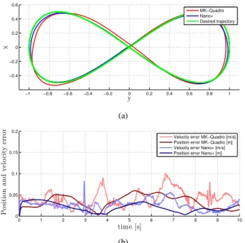
In Figure 5, the results of the first set of experiments are demonstrated. The desired trajectory was compared to the achieved trajectory for both vehicles. For the heavy MK-Quadro, we measured an average position error of 0.034 m and an average velocity error of0.042 m/s. The error did not exceed 0.062 m and 0.104 m/s, respectively. For the lighter Nano+, we found smaller average position errors of0.021 m which did not exceed 0.039 m. The velocity error was in average 0.026 m/s and always less than 0.058 m/s for the
Ground Take Off Brake Hover Formation Reconfiguration (Square) Semi-Autonomous Formation Formation Reconfiguration (Equilateral Triangle) Semi-Autonomous Formation Ground FlyTo Take Off Trajectory Playback Formation Reconfiguration (Tetrahedron) Formation UAVs ti me Brake Hover Semi-Autonomous Formation Land (vertically) Ground Scene:
Land (at Position) 10 14 21 21 24 34 3x Single UAV 72 81 114 120 121 125 146 150 158 160 3x 3x s Automatic Transitions
Event / User triggered Transitions
Single UAV
dynamically added to
the list of obstacle points of
the Formation UAVs
Single UAV
dynamically removed
from the list of obstacle points of
the Formation UAVs
Fig. 4: Experimental flow during the human controlled swarm experiment as described in Sec. V-B. The left and right
col-umn list the currently active Behavior for the quadrotors
in the swarm and the individual vehicle respectively. The time line is aligned to the attached video, also accessible
at http://antoniofranchi.com/videos/telekyb.html (see
Sec. VI-B).
Nano+ when ignoring an outlier caused by the tracking system at time 3 sec.
The results for the flight to a distant target are shown in Fig. 6. Both UAVs received the command after 0.3 seconds and accelerated up to their predefined maximum velocity. The heavier MK-Quadro started deceleration shortly before the Nano+ in order to stop and hover above the assigned goal location. Both vehicles stopped within 0.02 m of the target. B. Experiment with a Swarm and Human In-the-loop
The experiment of the more complex swarm flight demon-strated the capabilities of the behavior based architecture.
−1 −0.8 −0.6 −0.4 −0.2 0 0.2 0.4 0.6 0.8 1 −0.4 −0.2 0 0.2 0.4 0.6 y x MK−Quadro Nano+ Desired trajectory (a) 0 1 2 3 4 5 6 7 8 9 10 0 0.05 0.1 0.15 0.2 time [s] P o si ti o n a n d v el o ci ty er ro r
Velocity error MK−Quadro [m/s] Position error MK−Quadro [m] Velocity error Nano+ [m/s] Position error Nano+ [m]
(b)
Fig. 5: Trajectory of the Nano+ and the MK-Quadro along a eight shaped against the desired trajectory. (a) Position of the quadrotors together with the desired trajectory and (b) Norm of the position and velocity tracking errors during one traversal of the trajectory for both vehicles.
0 0.5 1 1.5 2 2.5 3 3.5 4 0 0.5 1 1.5 2 time [s] D is ta n ce to ta rg et [m ] MK−Quadro Nano+
Fig. 6: Distance to the target for a Nano+ and an MK-Quadro in a sidestep maneuver. Both velocity and acceleration were saturated for safety reasons as evident from the plots.
Fig. 4 depicts the experimental flow during this demonstra-tion. Additionally, a descriptive video of this experiment is attached to this submission and can also be accessed at
http://antoniofranchi.com/videos/telekyb.html.
At multiple times (e.g., at 24, 34, 72, 81, 146, 150 sec) the 4 UAVs switched from or to a formation which required an exchange of some information among the robots such as current poses and inter-distances of neighboring UAVs. Note that formation control was implemented in a completely decentralized way, thus not requiring theExperimental Flow
Manager or any other centralized controller.
At second 34, a single UAV left the formation and the remaining UAVs rearranged into a equilateral triangle. Si-multaneously, the Experimental Flow Manager reconfigured
the Obstacle Avoidance Processor Module of the remaining
swarm to consider the single UAV as an obstacle. At sec-ond81, this UAV landed at a predefined position to undergo a simulated maintenance, while the remaining UAVs kept being in control of the human operator. After having taken
off again, the single UAV entered a circular trajectory until it rejoined the formation at second146 upon user command. After160 sec, all UAVs landed vertically.
VII. CONCLUSION
In this paper, we introduced a control framework for quadrotor UAVs called TeleKyb. We demonstrated that TeleKyb presents a complete end-to-end solution containing all the necessary components from drivers for human input devices to hardware support for quadrotors from different manufacturers. Complex experimental setups for high-level robotic tasks such as exploration or mapping can be created without in-depth knowledge of control theory. Nevertheless, by relying on ROS for inter process communication and well defined interfaces, TeleKyb can be easily extended to meet new requirements. The controller included in TeleKyb was proven to work well with completely different quadrotor UAVs. In the past, early versions of TeleKyb have been already used successfully for various applications [8], [13], [14].
With the release of the TeleKyb source code into a public ROS repository, we are hoping for contributing the sharing our knowledge with the robotics community, as well as receiving a valuable feedback on our work.
A. Future Work
Currently, we are working on the integration of a filter to allow for the use of TeleKyb with noisy low-frequency posi-tion data from, e.g., GPS or on-board visual state estimates.
VIII. ACKNOWLEDGEMENTS
Volker Grabe wishes to thank Dr. Davide Scaramuzza for hosting his visit at the University of Zurich in 2012/2013 and for providing the Nano+ quadrotor used in the experiments.
REFERENCES
[1] A. Makarenko, A. Brooks, and T. Kaupp, “On the benefits of making robotic software frameworks thin,” in Workshop on Measures and Procedures for the Evaluation of Robot Architectures and Middleware at the 2007 IEEE/RSJ Int. Conf. on Intelligent Robots and Systems, San Diego, CA, Oct. 2007.
[2] A. Brooks, T. Kaupp, A. Makarenko, S. Williams, and A. Oreb¨ack, “Orca: A component model and repository,” in Software Engineering for Experimental Robotics, ser. Tracts in Advanced Robotics, D. Bru-gali, Ed. Springer, 2007, vol. 30, pp. 231–251.
[3] G. Metta, P. Fitzpatrick, and L. Natale, “YARP: Yet Another Robot Platform,” International Journal of Advanced Robotic Systems, vol. 3, no. 1, pp. 43–48, 2006.
[4] M. Quigley, K. Conley, B. Gerkey, J. Faust, T. Foote, J. Leibs, R. Wheeler, and A. Y. Ng, “ROS: an open-source Robot Operating System,” in Workshop on Open Source Software in Robotics at the 2009 IEEE Int. Conf. on Robotics and Automation, Kobe, Japan, May 2009.
[5] R. Simmons and D. James, Inter-Process Communication A Reference Manual. Carnegie Mellon University, 2011. [Online]. Available: http://www.cs.cmu.edu/˜ipc/
[6] J. Engel, J. Sturm, and D. Cremers, “Accurate figure flying with a quadrocopter using onboard visual and inertial sensing,” in Workshop on Visual Control of Mobile Robots (ViCoMoR) at the 2012 IEEE/RSJ Int. Conf. on Intelligent Robots and Systems, Vilamoura, Portugal, Oct. 2012.
[7] M. Achtelik, M. Achtelik, S. Weiss, and R. Siegwart, “Onboard IMU and monocular vision based control for MAVs in unknown in- and outdoor environments,” in 2011 IEEE Int. Conf. on Robotics and Automation, Shanghai, China, May 2011, pp. 3056–3063.
[8] A. Franchi, C. Secchi, M. Ryll, H. H. B¨ulthoff, and P. Robuffo Gior-dano, “Shared control: Balancing autonomy and human assistance with a group of quadrotor UAVs,” IEEE Robotics & Automation Magazine, Special Issue on Aerial Robotics and the Quadrotor Platform, vol. 19, no. 3, pp. 57–68, 2012.
[9] B. Hannaford and A. M. Okamura, “Haptics,” in Springer Handbook of Robotics, B. Siciliano and O. Khatib, Eds. Springer, 2008, pp. 719–739.
[10] C. Masone, A. Franchi, H. H. B¨ulthoff, and P. Robuffo Giordano, “Interactive planning of persistent trajectories for human-assisted nav-igation of mobile robots,” in 2012 IEEE/RSJ Int. Conf. on Intelligent Robots and Systems, Vilamoura, Portugal, Oct. 2012, pp. 2641–2648. [11] M. Riedel, “Telekyb: A modular software framework for bilateral teleoperation scenarios and its applications in robotics research,” Master Thesis, Eberhard Karls Universit¨at T¨ubingen, 2012. [12] J. L¨achele, A. Franchi, H. H. B¨ulthoff, and P. Robuffo Giordano,
“SwarmSimX: Real-time simulation environment for multi-robot sys-tems,” in 3rd Int. Conf. on Simulation, Modeling, and Programming for Autonomous Robots, Tsukuba, Japan, Nov. 2012.
[13] A. Franchi, C. Masone, V. Grabe, M. Ryll, H. H. B¨ulthoff, and P. Robuffo Giordano, “Modeling and control of UAV bearing-formations with bilateral high-level steering,” The International Jour-nal of Robotics Research, Special Issue on 3D Exploration, Mapping, and Surveillance, vol. 31, no. 12, pp. 1504–1525, 2012.
[14] A. Franchi, C. Secchi, H. I. Son, H. H. B¨ulthoff, and P. Robuffo Giordano, “Bilateral teleoperation of groups of mobile robots with time-varying topology,” IEEE Trans. on Robotics, vol. 28, no. 5, pp. 1019–1033, 2012.