Doi:http://dx.doi.org/10.4995/ASCCS2018.2018.****
Characterisation of beam-to-column joints beyond current
Eurocode provisions
J.-F. Demonceau
a* and A. Ciutina
baUrban and Environmental Engineering (UEE), University of Liege, Belgium
b Department of Overland Communication Ways, Foundation and Cadastral Survey, University Politehnica
Timisoara, Romania
*corresponding author, e-mail address: [email protected]
Abstract
In EN 1994-1, design rules are given for the evaluation of the mechanical properties of structural steel-concrete composite joints (rotational stiffness, resistance and ductility) based on the component method offered in EN 1993-1-8 and adding specific components for composite joints. These rules cover only the situations for the joints subjected to shear forces and hogging moments.
However, during the last decades, researches have been conducted on the behaviour of composite joints subjected to different kind of actions such as sagging bending moments, cyclic loadings, combined bending moments and axial loads, elevated temperatures etc. with the objective of improving/extending the rules presently proposed in the Eurocodes design rules.
As an outcome of the Technical Committee 11 of the European Convention of Constructional Steelwork (ECCS) dedicated to the behaviour of composite structures, a publication summarising these recent developments and their main outcomes is under finalisation. Within the present paper, it is proposed to highlight these main outcomes which could be seen as proposals for future improvements of the beam-to-column provisions in Eurocodes in general and of Eurocode 4 in particular.
Keywords: composite joints, component method, static loading, cyclic loading.
1. Introduction
Nowadays, the component method is a widely recognised procedure for the evaluation of the design properties of structural joints. This method is the one recommended in the Eurocodes for the characterisation of structural joints and applies to any type of steel or composite joints, whatever the geometrical configuration, the type of loading (axial force and/or bending moment...) and the type of member sections.
This method considers any joint as a set of individual basic components modelled as springs – see Fig. 1. Each of these components possesses its own strength and stiffness either in tension or in compression or in shear. The column web is subject to coincident compression, tension and shear. This coexistence of several components within the same joint element can obviously lead to stress interactions that are likely to decrease
the resistance of the individual basic components; the latter is taken into account within the method.
The application of the component method requires the following steps: (i) identification of the active components in the joint being considered; (ii) evaluation of the stiffness and/or resistance characteristics for each individual basic component in terms of specific characteristics: initial stiffness, design resistance etc. or the whole deformability curve and; (iii) assembly of all components and evaluation of the stiffness and/or resistance characteristics of the whole joint in specific characteristics: initial stiffness, design resistance etc. leading to a final moment-rotation design curve.
The application of the component method requires a sufficient knowledge of the behaviour of the basic components. Those covered by Eurocode 3 for steel joints are listed in Table 1
(components 1 to 12); those covered by Eurocode 4 for composite joints are identical to the steel joints by considering two additional components also presented in Table 2 (components 13 and 14). Also, Eurocode 4 covers components which are reinforced by the presence of concrete (column web panel in shear or column web in compression in a composite column). The combination of these components allows to cover a wide range of joint configurations. However, the rules as presently given in the Eurocodes only cover the situations for the joints subjected to shear forces and hogging moments. It is the reason why, during the last decades, researches have been conducted on the behaviour of composite joints subjected to different kind of actions such as sagging bending moments, cyclic loadings, combined bending moments and axial loads, elevated temperatures etc. with the objective of improving/extending the rules presently proposed in the Eurocodes design rules. h1 h2 k1 k2 k j Mj eq z k3,2k4,2k5,2k10,2 k13,1 k 1 k2 j k k k j eff,2 1 2 keff,1= k13,1 Mj Mj a) b) c)
Fig. 1. Example of a spring model for a composite flush end-plate connection [1]. Table 1. Components covered by Eurocode 3 and
Eurocode 4.
N° Components
1 Column web panel in shear
2 Column web in compression
3 Beam flange and web in compression
4 Column flange in bending
5 Column web in tension
6 End-plate in bending
7 Beam web in tension
8 Flange cleat in bending
9 Bolts in tension
10 Bolts in shear
11 Bolts in bearing (on beam flange,
column flange, end-plate or cleat)
12 Plate in tension or compression
13 Longitudinal steel rebars in tension
14 Steel contact plate in compression
As an outcome of the Technical Committee 11 of the European Convention of Constructional Steelwork (ECCS) dedicated to the behaviour of composite structures, a publication summarising these recent developments and their main outcomes is under finalisation. Next sections, highlight a part of the main outcomes which could be seen as proposals for future improvements of the beam-to-column provisions in Eurocodes in general and of Eurocode 4 in particular.
2. Composite joints under static loading
As previously mentioned, the present draft of the Eurocodes already allows covering and characterising composite joints but are still limited on different aspects.
In particular, only composite joints under hogging moments are covered while, in practice, such joints can also be subjected to sagging bending moments and/or to axial forces. It is for instance the case when considering the behaviour of composite sway frames in which sagging moments at the extremities of the composite beams may occur or the behaviour of composite structures subjected to exceptional events such as the loss of a column, scenario in which the beam extremities are subjected to hogging or sagging bending and tensile loads (membrane forces). In the next sections, the behaviour of beam-to-column composite joints under sagging moment and under M-N loading is under consideration.
2.1. Composite joints under sagging moments Using the component method as presently proposed in the Eurocodes, it is not yet possible to predict the behaviour of composite joints subjected to sagging bending moments. Indeed, no method is available to characterise one of the activated components under such loading which is the concrete slab in compression.
In recent researches, methods to characterise this component in term of « resistance » are proposed. Their aim is to define a rectangular cross section (with a width beff,conn and a height z) of concrete participating to the joint resistance. The procedure which is described in this section combines two methods proposed respectively by F. Ferrario [2] and by J.Y.R. Liew [3]. The combination of these two methods permits to reflect in a more appropriate way how the
concrete resists to the applied load in the vicinity of the joint as demonstrated in [4-5].
For the definition of the width of concrete
beff,conn to be considered at the vicinity of the joints, the definition proposed by Ferrario in [2] is used:
, 0, 7
eff conn c c eff
b b h b (1)
where bc is the width of the column profile
flange, hc the height of the column profile cross
section and beff, the effective width of the
concrete/composite slab to be considered in the vicinity of the joint; bc represents the
contribution of the concrete directly in contact with the column flange while 0,7.hc the
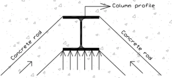
contribution of the developed concrete rods in the “strut-and-tie” behaviour (see Fig. 2).
Fig. 2. Plane view of the slab in the vicinity of the joint - development of concrete rods
in compression under sagging moment
For the definition of the height z of the component “concrete slab in compression”, the method proposed by Liew [3] is selected: - the characterisation of the joint components
in tension and eventually in shear is performed according to the rules recommended in the Eurocodes;
- then, the height of the concrete/composite slab contributing to the joint behaviour is computed by expressing the equilibrium of
the load developing in the
concrete/composite slab in compression with the components activated in tension or in shear and assuming a rectangular stress distribution in the concrete (equal to 0,85 fck/c in a design): , , .(0,85. / ) Rd i i concrete eff conn ck c F z h b f
(2)where hconcrete is the total height of the concrete slab (in case of a composite slab,
hconcrete is equal to the concrete above the ribs)
and FRd,i is the tensile resistance of bolt row i;
- finally, the characterisation of the joint is performed assuming that the centre of compression is located at the middle of the height of the contributing part of the concrete slab (z).
The two previously mentioned references [2-3] only deal with the characterisation of the component “concrete slab in compression” in term of resistance but no formulas are proposed to characterise the latter in term of stiffness; however, this is requested in order to be able to predict the initial stiffness of the joint (and to derive the moment-rotation curve).
If reference is made to [6] a formula is proposed to predict the stiffness of a concrete block against a rigid plate. In the present case, the steel column encased in the concrete slab can be considered as a rigid plate; so, the formula proposed in [6] can be extended to the present situation to compute the stiffness of the component under consideration:
, csc . . 1, 275. c eff conn a E b z k E (3)
where EC is the secant Young modulus for the concrete, Ea, the elastic Young modulus for the steel and kCSC, the stiffness of the component “concrete slab in compression” to be considered in the component method.
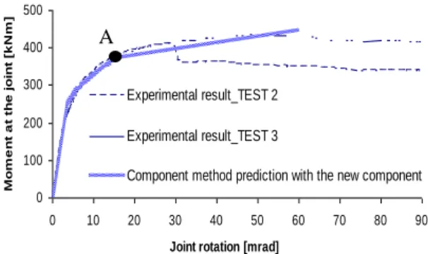
In [4], the so-defined analytical procedure is validated through comparisons with results from experimental tests performed on composite joints in isolation. An example of such comparison is presented in Fig. 3 where the analytical prediction is compared to results obtained at Trento University [7] through experimental tests conducted on external composite joints within a European RFCS project called PRECIOUS in which the University of Liege was also involved.
In Fig. 3, it can be observed that two experimental curves are reported. They are distinguished by the configuration of the slab: the TEST 2 joint is composed of a composite slab while the TEST 3 one is composed of a concrete slab. From the comparison presented in Fig. 3, it can be observed that a very good agreement is obtained between the analytical prediction and the experimental results. For TEST 2, a loss of resistance in the joint is observed at a rotation of 29 mrad which is not reflected by the analytical prediction. In fact, this
loss of resistance during the test was associated to a lack of ductility of the concrete in the vicinity of the connection, phenomenon not yet covered by the proposed analytical procedure. However, as the objective with the analytical model is to predict the plastic resistant moment (point A on Fig. 3) which is reached before this lack of ductility, this phenomenon does not call into question the validity of the model.
Fig. 3. Joints under sagging moments - Comparisons analytical prediction vs.
experimental results
2.2. Composite joints under M-N
In the Eurocodes, the proposed rules are mainly devoted to the characterization of joints subjected to bending moments and shear forces. It is the reason why, in Part 1.8 of Eurocode 3 dedicated to the design of steel joints, the proposed field of application is limited to joints in which the force NEd, (also noted N in the paper for sake of simplicity – and the same applies to
MEd, noted M) acting in the joint remains lower than 5% of the axial design resistance Npl,Rd of the connected beam (and not of the joint what is quite surprising as far as the influence of the applied axial load on the joint response is of concern). Under this limit it is considered that the rotational response of the joints is not significantly influenced by the axial forces. It has however to be stated that this value is a fully arbitrary one and is not at all scientifically justified. However, in some situations, these joints can be subjected to combined axial loads and bending moments, e.g. in the extremities of inclined roof beams or in frames subjected to an exceptional event leading to the loss of a column, situation where significant tying forces can developed in the structural beams above the lost column.
If the above-mentioned criterion is not satisfied, the Eurocodes recommend to check the resistance by referring to “M-N” interaction
diagram defined by the polygon linking the four points corresponding respectively to the hogging and sagging bending resistances in absence of axial forces and to the tension and compression axial resistances in absence of bending.
The PhD thesis of Cerfontaine [8], demonstrates that the proposed method is questionable and can even be unsafe in many situations. In consequence an improved design analytical procedure, based on the component method concept, was (i) developed by Cerfontaine [8] to predict the response of ductile and non-ductile steel joints subjected to combined axial loads and bending moments and (ii) extended to composite joints in [4] (see also [9]). The model, including a worked example is fully described in [4] and is freely available for downloading.
The validity of the proposed analytical procedure was checked through comparisons to results of experimental tests performed in Stuttgart in the framework of an RFCS project [10]. Fig. 4 shows the comparison of the obtained analytical predictions to the experimental test results. On the latter, it can be observed that two analytical curves are reported: - One named “plastic resistance curve” which is computed with the elastic strengths of the materials and;
- One named “ultimate resistance curve” which is computed with the ultimate strengths of the materials.
Fig. 4. Comparison of the resistance interaction curves
According to Fig. 4 the computed analytical curves are in very good agreement with the experimental results. Indeed, the experimental curves are between the plastic and ultimate analytical resistant curves, which is in line with the loading sequence followed during the tests.
0 100 200 300 400 500 0 10 20 30 40 50 60 70 80 90
Joint rotation [mrad]
Mo m e n t a t th e j o in t [k N m ] Experimental result_TEST 2 Experimental result_TEST 3
Component method prediction with the new component
-80 -70 -60 -50 -40 -30 -20 -10 0 10 20 30 40 50 60 70 0 50 100 150 200 250 300 350 400 450 500 550 600 650 700 M [kN] N [kN]
Analytical prediction_plastic resistance curve Analytical prediction_ultimate resistance curve Experimental results_TEST 1 Experimental results_TEST 2 Experimental results_TEST 3 Experimental results_TEST 4 Experimental results_TEST 5 HO G G ING MOME NT S S A GG ING M OMENT S TENSION A
In the hogging moment zone, it can be observed that for very small values of tensile loads, the experimental curves are close to the ultimate analytical one which is logical, as a bending moment close to the ultimate resistant bending moment of the joint was first applied to the tested specimen before applying the tensile load. Then, when the tensile load is increasing, the experimental curves first deviate from the ultimate analytical one to finally come back close to the ultimate analytical curve (except for TEST 1). This phenomenon can be explained by the fact that, in order to pass from the ultimate hogging moment to the ultimate tensile resistant load, different components are activated; indeed, the component which is associated to the ultimate hogging moment is “beam flange in compression” while the one associated to the ultimate tensile load is the component “column flange in bending”.
This phenomenon is not observed in the sagging moment zone: indeed, as shown in Fig. 4, the experimental curves are close to the ultimate analytical one from the pure bending to the ultimate tensile load. Similarly this results in agreement with the component activated from the pure bending to the ultimate tensile load which is the same in the present case, i.e. the component “column flange in bending”.
Through this comparison, it can be concluded that the proposed analytical model is validated.
3. Composite
joints
at
elevated
temperatures
In case of fire, the beam-to-column joints play a key role in the global structural response. These joints, initially loaded in bending, may be subjected to elevated temperatures and to combined axial load “N” and bending moment “M”. Within the RFCS project Robustfire, a methodology to predict the mechanical response of bolted composite beam-to-column joints at elevated temperatures under M-N has been developed [11-12].
This methodology is based on the analytical method presented in the previous section able to predict M-N resistance interaction curves for joints and which is in full agreement with the Eurocode model recommended for the joint characterisation, i.e. the component method.
The procedure described in the previous section can be applied at elevated temperature
provided that the temperature distribution in the joint is known. Each component resistance is then simply evaluated based on the material resistance at its given temperature.
The validation of the proposed model has been performed through comparisons against experimental results obtained from six fire tests performed at the University of Coimbra on a composite steel-concrete beam-to-column frame. The tested composite frame was subject to mechanical (bending and axial forces) and thermal actions (constant temperature equal to 500ºC or 700ºC). The objective of the experiments was to observe the combined bending moment and axial loads in the heated joint when catenary action develops in the frame during a column loss due to a localized fire.
An example of comparison is given in Fig. 5. In this figure, it can be observed that a very good agreement is obtained between the analytical predictions and the experimental results. Similar safe agreements were confirmed through the comparisons to the other tests results.
Fig. 5. Comparison of the experimental resistances to the analytical curve for TEST 6 (composite joint at 700°C) [11]
Accordingly, knowing the temperatures at the level of the joint components, the analytical model is able to predict the joint resistance for any M-N couples. A perspective to the presented study is to propose in the future a full analytical procedure, including the estimation of the component temperatures, considering what is already proposed for a specific joint configuration in [13] as, in current evaluations, a 3D thermal FEM analysis is still required to predict these temperatures in practice.
4. Composite joints under cyclic loading
In many situations the structures are subjected to alternate lateral loading, such is the case of seismic load or high wind loads. In these cases, the composite joints can be subjected to alternating moments, changing from hogging to
sagging and consequently the behaviour under cyclic loading plays a crucial role in the overall structural behaviour.
For seismic design, the Section 7 of EN 1998-1 contains additional requirements for seismic-resistant steel and concrete composite buildings.
In a general manner, the cyclic behaviour is dependent on the connection typology and the characteristics of its constitutive components in terms of resistance, stiffness and ductility. In accordance with the seismic design norm EN 1998-1, the designer can chose to (i) guide the plastic hinge formation in the connected element (e.g. the beam), this leading in most of the cases to haunched or reinforced joints or (ii) to assure the plastic hinge formation within the joint, case in which the ductility of the joint must be proven by testing evidence. However, the last possibility is not really considered by seismic designers as the experimental tests delay the execution time of the building. Also, EN 1998-1 constrains the shear design force of the column web panel to
0.8Vwp,Rd (clause 7.5.4) and limits its cyclic
deformation to maximum 30% of the joint rotation (clause 6.6.4).
4.1. Global cyclic behaviour
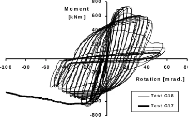
Considering the global behaviour presented in section 2, the cyclic response of joints remains highly unsymmetrical due to the presence of the concrete slab. -8 0 0 -6 0 0 -4 0 0 -2 0 0 0 2 0 0 4 0 0 6 0 0 8 0 0 -1 0 0 -8 0 -6 0 -4 0 -2 0 0 2 0 4 0 6 0 8 0 R o ta ti o n [m r a d . ] M o m e n t [k N m ] T e s t G1 8 T e s t G1 7
Fig. 6. Unsymmetrical behaviour of composite joints [14].
Fig. 6 presents the cyclic response (G18) of an external composite continuous joint (T joint) in comparison with a monotonic loaded specimen (G17). In a general manner, the cyclic loading introduces an important reduction of joint ductility, which could be accompanied by a reduction of the maximum resistance of the joint. However, in case of internal joints (cruciform)
loaded asymmetrically, the response become symmetrical (see Fig. 7) by diagonal tension and compression components.
4.2. Influence of composite components on cyclic behaviour
The design of composite joints is done in accordance with the Section 8 of EN 1994 which relies on the EN1993-1-8 by considering two additional composite components that related to: - concrete slab elements in tension
(reinforcement);
- encasement of column web panel in shear. Although the results of cyclic testing on composite joints tends to validate the component resistances in hogging, the design norm is totally uncovered for sagging moments as presented in section 2.
In an overall behaviour, the concrete slab has a direct influence in the cyclic response of the joints by limiting the ductility in sagging bending (concrete in compression) even if offering a noticeable higher resistance and stiffness – See Fig. 6. Also, as shown by Braconi et al. [15], full-depth slabs guarantee more stable and small degradation of resistance for high deformation levels in comparison with pre-lattice girders and composite slabs with profiled sheeting.
Fig. 7. Cyclic behaviour of internal composite joints: crack pattern in case of encased web panel [16].
The second additional composite component – encasement of steel web panel in concrete does not lead to a real increase in cyclic resistance due to concrete cracking, thus reducing considerably the advantages of column web confinement [16]. The authors demonstrate also that during first cycles the cyclic stiffness degradation was important due to concrete cracking.
4.3. Failure assessment
Although the design resistances of composite joints could be fairly evaluated by existing norms and proposals such as reported in Section 2, the information given in regard with the ductility of joints is poor, and resumes to detailing rules for steel and concrete elements. In many cases the failure mechanisms are different in cyclic loading in regard to static monotonic loading due to high alternating stresses induced in brittle components.
The existing tests on composite joints have revealed that the rotation capacity could be reduced by components with limited capacity of deformation in cyclic loading, such as:
- heat affected zone of welds, including beam flange-to-end-plate or column flange welds. In case of sagging bending and increased level arm for tensioned elements as compared to pure steel joints, the beam flange welds and adjacent zone is subjected to high stresses. In low-cycle fatigue loading, these will lead to premature fractures:
- bolts in tension: considering that bolts have limited plastic strain, the bolt failure is accompanied by sudden decrease of joint resistance;
- concrete elements subjected to alternating tension and compression due to crack degradation, resistance drop and stiffness deterioration of joint behaviour. Concrete degradation can affect the integrity of the slab, the encasement of the column web or steel beam.
Fig. 8. Brittle cyclic failure of bolts in sagging for an end-plate connection [17].
In return, the following components could be classified as ductile, leading to high cyclic rotation capacity of beam-to-column joints in accordance with testing records:
- steel reinforcement in tension if proper anchorage is provided;
- column web panel in shear. However, the rotation is limited in accordance to EN 1998-1 requirements to maximum 30% of the joint total rotation;
- end-plate and column flange in bending which can contribute in some extent to adequate ductility of joints.
Fig. 9. Ductile cyclic behaviour of an end-plate connection–reinforcement in tension [16].
In conclusion, the failure mode of a composite joint subjected to cyclic loading could be routed towards a ductile behaviour by controlling the resistances of its components and assuring the failure in potential ductile components, both in sagging and hogging bending.
5. Conclusions
During the last decades, researches have been conducted on the behaviour of composite joints subjected to different kind of actions, not covered by current EN1994-1 provisions such as:
- joints under sagging bending moments; - influence of cyclic loadings;
- joints under combined bending moments and axial loads;
- joints under elevated temperatures etc. with the objective of improving/extending the rules presently proposed in the Eurocodes design rules.
Within the present paper, outcomes of some of these researches are reflected. Some of the presented results could be considered as proposals for future improvements of the beam-to-column provisions in Eurocodes in general and of Eurocode 4 in particular.
As an outcome of the Technical Committee 11 of the European Convention of Constructional
Steelwork (ECCS) dedicated to the behaviour of composite structures, a publication devoted to recent researches in the field of composite joints and in which the details of the developments presented herein are provided, amongst others, is under finalisation.
References
[1] Anderson D., Composite steel-concrete joints in frames for buildings: Design provisions. COST C1 – Semi-rigid behaviour of civil engineering structural connections, Luxembourg, 1999. [2] Ferrario F. “Analysis and modelling of the
seismic behaviour of high ductility steel-concrete composite structures”. PhD thesis, Trento University, February 2004.
[3] Liew R.J.Y., Teo T.H. and Shanmugam N.E., Composite joints subject to reversal of loading – Part 2: analytical assessments, Journal of Constructional Steel Research, 247-268, 2004. [4] Demonceau J.-F., Steel and composite building
frames: sway response under conventional loading and development of membranar effects in beams further to an exceptional action, PhD thesis presented at the University of Liege (http://orbi.ulg.ac.be/handle/2268/2740). [5] Demonceau J.-F., Jaspart J.-P., Klinkhammer R.,
Weynand K., Labory F. and Cajot L.-G., Recent
developments on composite connections:
behaviour of joints subjected to sagging bending moments and presentation of a free design dedicated software, Eurosteel 2008 in Graz, 447-452, 2008.
[6] Weynand K., Column bases in steel building frames. COST C1 – Semi-rigid behaviour of civil
engineering structural connections,
Luxembourg, 1999.
[7] Trento University. Partially reinforced-concrete-encased column joints for severe seismic loadings: tests and main results, Internal report
for the RFCS project RFS-CR-03034
“Prefabricated composite beam-to-column filled tube or partially reinforced-concrete-encased column connections for severe seismic and fire loadings”, March 2006.
[8] Cerfontaine, F., Study of the interaction between bending moment and axial force in bolted joints (in French). PhD presented at the University of Liege, 2003.
[9] Demonceau J.-F. and Jaspart J.-P., M-N
interaction in beam-to-column joints:
development of a design model, SEMC 2010 conference, Cape-Town, South-Africa, 643-646, 2010
[10] Kuhlmann U., Rölle L., Jaspart J.P., Demonceau J.F., Vassart O., Weynand K., Ziller C., Busse E., Lendering M., Zandonini R. & Baldassino N., Robust structures by joint ductility, Final Report, Science Research Development, European Commission, 2008.
[11] Haremza C., Santiago A., Demonceau J.-F., Jaspart J.-P., Simoes da Silva L., Composite joints under M-N at elevated temperaturas, Journal of Constructional Steel Research, Elsevier, 1 24, pp. 173-186, 2016.
[12] Demonceau J.-F., Haremza C., Jaspart J.-P., Santiago A. and Da Silva L. S., Composite joints
under M-N at elevated temperature:
Experimental investigations and analytical models, Composite Construction in Steel and Concrete VII, Palm Cover, Australia, 387-400, 2013.
[13] Demonceau J.-F., Hanus F., Jaspart J.-P. & Franssen J.-M (2009). Behaviour of single sided composite joints at room temperature and in case of fire after an earthquake, International Journal of Steel Structures, The Korean Society of Steel Construction, Vol. 9, pp. 329- 342, December 2009.
[14] Lachal A., Aribert J.M., Ciutina A., Seismic Performance of End-Plate Moment Resisting Composite Joints, Proceedings of Composite Construction in Steel And Concrete V, Mpumalanga, South Africa American Society of Civil Engineers – ASCE, ISBN 0-7844-0826-2. [15] Braconi A., Elamary A., Salvatore W., Seismic
behaviour of beam-to-column partial-strength joints for steel-concrete composite frames, Journal of Constructional Steel Research 66 (2010) 14311444.
[16] Rui S., da Silva L., Cruz P., (2001). Cyclic
behaviour of end-plate beam-to-column
composite joints, Steel and Composite
Structures, Vol. 1, No. 3 (2001) 355-376 [17] D. Dubina, A. Ciutina, A. Stratan. Cyclic Tests
on Bolted Steel and Composite Double-Sided Beam-to-Column Joints, International Journal of Steel & Composite Structures No.2, Apr.2002.
![Fig. 1. Example of a spring model for a composite flush end-plate connection [1].](https://thumb-eu.123doks.com/thumbv2/123doknet/6136915.156742/2.892.107.431.537.717/fig-example-spring-model-composite-flush-plate-connection.webp)
![Fig. 5. Comparison of the experimental resistances to the analytical curve for TEST 6 (composite joint at 700°C) [11]](https://thumb-eu.123doks.com/thumbv2/123doknet/6136915.156742/5.892.468.788.570.725/comparison-experimental-resistances-analytical-curve-test-composite-joint.webp)
![Fig. 8. Brittle cyclic failure of bolts in sagging for an end-plate connection [17].](https://thumb-eu.123doks.com/thumbv2/123doknet/6136915.156742/7.892.467.785.294.491/fig-brittle-cyclic-failure-bolts-sagging-plate-connection.webp)
