Publisher’s version / Version de l'éditeur:
Vous avez des questions? Nous pouvons vous aider. Pour communiquer directement avec un auteur, consultez la première page de la revue dans laquelle son article a été publié afin de trouver ses coordonnées. Si vous n’arrivez pas à les repérer, communiquez avec nous à [email protected].
Questions? Contact the NRC Publications Archive team at
[email protected]. If you wish to email the authors directly, please see the first page of the publication for their contact information.
https://publications-cnrc.canada.ca/fra/droits
L’accès à ce site Web et l’utilisation de son contenu sont assujettis aux conditions présentées dans le site LISEZ CES CONDITIONS ATTENTIVEMENT AVANT D’UTILISER CE SITE WEB.
Proceedings from the Fifth International Symposium on Tunnel Safety and
Security, New York, USA, March 14-16, 2012, SP Report, pp. 309-318,
2012-03-14
READ THESE TERMS AND CONDITIONS CAREFULLY BEFORE USING THIS WEBSITE.
https://nrc-publications.canada.ca/eng/copyright
NRC Publications Archive Record / Notice des Archives des publications du CNRC :
https://nrc-publications.canada.ca/eng/view/object/?id=1d5f7a9c-7b99-444d-a2a6-02140f9625a2 https://publications-cnrc.canada.ca/fra/voir/objet/?id=1d5f7a9c-7b99-444d-a2a6-02140f9625a2
NRC Publications Archive
Archives des publications du CNRC
This publication could be one of several versions: author’s original, accepted manuscript or the publisher’s version. / La version de cette publication peut être l’une des suivantes : la version prépublication de l’auteur, la version acceptée du manuscrit ou la version de l’éditeur.
Access and use of this website and the material on it are subject to the Terms and Conditions set forth at
Some effects on natural ventilation system for subway tunnel fires
Kashef, A.; Yuan, Z.; Lei, B.
Some effects on natural
ventilation system for subway
tunnel fires
Kashef, A.; Yuan, Z.; Lei, B.
NRCC-54599
A version of this document is published in: Fifth International Symposium on Tunnel Safety & Security.
Proceedings, New York, N.Y. USA, March14-16, 2012
The material in this document is covered by the provisions of the Copyright Act, by Canadian laws, policies, regulations and international agreements. Such provisions serve to identify the information source and, in specific instances, to prohibit reproduction of materials without written permission. For more information visit http://laws.justice.gc.ca/en/showtdm/cs/C-42
Les renseignements dans ce document sont protégés par la Loi sur le droit d’auteur, par les lois, les politiques et les règlements du Canada et des accords internationaux. Ces dispositions permettent d’identifier la source de l’information et, dans certains cas, d’interdire la copie de documents sans permission écrite. Pour obtenir de plus amples renseignements : http://lois.justice.gc.ca/fr/showtdm/cs/C-42
Some Effects on Natural Ventilation System for Subway
Tunnel Fires
Ahmed Kashef a,*, Zhongyuan Yuan b, Bo Lei b
a
Institute for Research in Construction, National Research Council, Canada
b
School of Mechanical Engineering, Southwest Jiaotong University, China
ABSTRACT
A series of experiments, using a 1:15 model tunnel, were designed in accordance with the Froude conservation approach to investigate the influential parameters on temperature distributions in tunnel fires with natural ventilation. The effect of parameters such as fire size, shaft length and height were investigated. A natural ventilation system was achieved by introducing four vertical shafts spaced at 4 m in the ceiling of the tunnel. In the study reported in this paper, propane gas, located on the floor of the tunnel, was used to simulate the fire source which produced heat release rates in the range of 3.61kW to 12.2 kW. The smoke temperature distributions along the tunnel ceiling and in the vertical direction along the tunnel length were measured using K-type thermocouples trees. Based on the fire plume theory, a dimensionless temperature was defined and it was found that the fire size did not have a major effect on the dimensionless temperature. Despite the fact that the shaft sizes did not
significantly affect the distribution of the temperature in the near-field of the fire, they did influence the temperature values with the temperatures dropping with the increase of shaft size. Based on the one-dimensional theory and rational assumptions, two formulas were developed to predict the ceiling longitudinal temperature distribution in tunnel fires with natural ventilation.
KEYWORDS: tunnel fires, natural ventilation, model scale experiments, Froude modeling.
INTRODUCTION
Natural ventilation schemes with openings in the roof can be utilized in subway tunnels to provide both normal and emergency ventilation. Compared to the traditional ventilation schemes, the natural ventilation mode could offer savings in capital investment dollars on the requirements for large ventilation plants. Moreover, natural ventilation systems could significantly help reduce the production of greenhouse gas emission or carbon footprint. However, utmost care should be taken during the design of subway tunnel natural ventilation systems as to how to control smoke movement in order to ensure the safety of evacuees.
In recent years a great deal of research has been conducted to investigate tunnel fires with forced ventilation systems. Concepts such as “critical ventilation”, “smoke backlayering length”, etc., were developed as results of enormous research work [1-5]. On the other hand, natural ventilation schemes have not been the subject of much of the research work. Smoke diffusion characteristics under a natural ventilation system were investigated [6-9]. Using a reduced-scale experimental approach, Yuan [6] investigated ceiling temperature distribution and smoke extraction through a natural
ventilation shaft. Yuan [7] applied the Computational Fluid Dynamics (CFD) technique to investigate the maximum shaft interval distances required to ensure tenable conditions in tunnels. Through the full-scale experiments and CFD technique, Wang [8, 9] researched the smoke diffusion characteristics in tunnel fire with natural ventilation.
The experiments reported here are a subset of a much larger study on the impact of natural ventilation in tunnels and the effects of the fire size and shaft size on longitudinal ceiling temperature and vertical
temperature were examined. This series of experiments were conducted on a model tunnel to understand the smoke diffusion properties in tunnel fires with natural ventilation. Based on the analysis of the experimental data, formulas to predict ceiling temperature distribution were developed.
REDUCED-SCALE EXPERIMENTS
Model tunnel and experiment setup
A reduced-scale tunnel (1:15 scale) was used in this study. The tunnel model was 17 m long, 0.32 m high and 0.7 m wide. The boundaries of the tunnel were made of cement boards with a thickness of 10 mm. In order to be able to observe smoke diffusion in the tunnel, 4 glass windows were
constructed on one side wall of the tunnel. To simulate the natural ventilation system, 4 cuboid shafts, made of gypsum board, were introduced in the tunnel ceiling in the middle of the width dimension. The shafts were arranged at interval distances of 4 m. To investigate the effect of the shaft size on smoke diffusion, 6 different shaft sizes, as shown in the Table 1, were used in the study. A schematic layout of the reduced-scale tunnel is shown in Figure 1a.
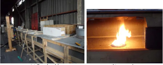
(a) Tunnel model (b) propane burner
Figure 1 Layout of the reduced-scale tunnel
The porous bed burner of 178 mm diameter, used to simulate the fire source, was placed on the middle of the tunnel floor. Propane gas was used as the fuel source (Figure 1b). The produced heat release rates were regulated using a rotameter and a manometer. Different fire sizes in the range of 3.2 kW to 14.5 kW were used in the full study to investigate the effect of fire size on the tunnel fire dynamics although only those in the range of 3.61kW to 12.2kW are reported in this paper. The 3.2 kW to 14.5 kW heat release rates corresponded to a full scale range of 2.8 MW to 12.6 MW. To examine the smoke diffusion along the tunnel ceiling and the smoke temperature distributions under the ceiling, K-type thermocouples trees were used. A horizontal thermocouple tree was placed 10 mm under the tunnel ceiling. Five vertical thermocouples trees, five thermocouples per each tree, were installed at different tunnel cross-section. The five thermocouples were placed at distances from the ceiling of 10 mm, 60 mm, 110 mm, 160 mm, and 210 mm. One vertical tree was placed at the fire location, two were installed upstream of the fire and two vertical trees were placed downstream of the fire. All measurement points were set along the tunnel centerline. The sketch of the arrangement of thermocouples is shown in Figure 2.
Figure 2 Sketch of thermocouples arrangement
A hotwire anemometer was used to measure smoke temperature and smoke volume flow through the shafts. Four anemometers were used in the two shafts surrounding the fire. The volumetric flow of the smoke through these shafts was then calculated multiplying the shaft area and the average airflow velocities.
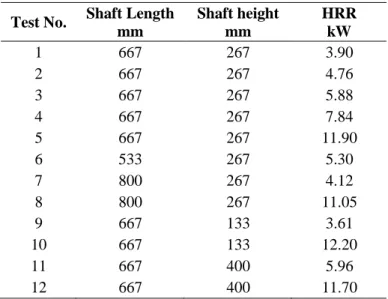
More than 100 tests were conducted to examine several influential parameters. The examined parameters included: fire size, fire location, shaft size (height and length), and tunnel grade. This paper presents the twelve tests conducted to investigate the effect of the three parameters; fire size, shaft height and shaft length on fire dynamics in a naturally ventilated tunnels. The test conditions of the 12 experiments are summarized in Table 1.
Table 1 Test conditions
Test No. Shaft Length mm Shaft height mm HRR kW 1 667 267 3.90 2 667 267 4.76 3 667 267 5.88 4 667 267 7.84 5 667 267 11.90 6 533 267 5.30 7 800 267 4.12 8 800 267 11.05 9 667 133 3.61 10 667 133 12.20 11 667 400 5.96 12 667 400 11.70 Scaling Law
The Froude number conservation is usually adopted as a scaling technique in reduced-tunnel fire experiments to relate the model to the full-scale.
2 V Fr
gL
= (1) where g is the gravitational acceleration, V and L are the characteristic values of velocity and length, respectively. From the Froude number conservation, the relationships for the heat release rate, Q, smoke velocity, V, and smoke temperature, T, of the model tunnel (subscript M) and full-scale tunnel (subscript F) can be expressed as follows:
5/ 2 ( / ) M F M F Q =Q L L VM=VF(LM/LF)1/2
(2)
M F T =T TunnelNatural ventilation shaft
Thermocouple
Propane gas Burner
RESULTS AND DISCUSSIONS
The following sections of the paper present the results of 12 experiments conducted to investigate the effect of three parameters; namely, fire size, shaft height and shaft length on the smoke diffusion in naturally ventilated tunnels.
Effect of fire size on temperature distribution
The maximum temperature rise of the smoke, △Tmax, can be expressed in terms of the dimensionless
heat release rate, Q*, and the ambient temperature, To, as follows [10]:
2/3 max 0
T
Q
T
∗∆
∝
where: (3) Q*= Q ρoCPToH�gHwhere ρo is the ambient temperature (kg/m 3
), H is the height of the tunnel (m), CP is the specific heat
(J/kg K). In order to facilitate the investigation of the effect of heat release rate on the temperature distribution, the temperature rise is defined in a non dimensionless form as follows:
* 2/3 0
T
T
Q
∗T
∆
∆
=
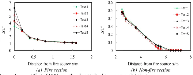
(4) In this paper, the effect of heat release rate (fire size) on the temperature distribution was investigated for a shaft size of 667 mm in length, 167 mm in width, and 267 mm in height. The fire size ranged from 3.9 kW to 11.9 kW (Tests 1 through 5 in Table 1). In order to simplify descriptions, the model tunnel was virtually divided into two regions: the tunnel section containing the fire source was defined as the “fire section” and the rest of the tunnel was defined as the “non-fire section”. The ceiling longitudinal dimensionless temperature rise was plotted against the longitudinal distance from the fire source as shown in Figure 3. Figure 3 shows that for the five different fire sizes, the temperatures under the ceiling in the longitudinal direction are almost the same except for the thermocouple tree above the fire source. For small fire sizes, the flame did not impinge on the tunnel ceiling and therefore the temperature of the thermocouple above the fire source represented the centerline plume temperature. However, for the larger fire sizes, the flame impinged on the tunnel ceiling and the measured temperature represented the flame temperature.(a) Fire section (b) Non-fire section
Figure 3 Effect of HRR on ceiling longitudinal temperature distribution
0 1 2 3 4 5 6 7 0 0.5 1 1.5 2 ∆ T *
Distance from fire source x/m Test 1 Test 2 Test 3 Test 4 Test 5 0 0.1 0.2 0.3 0.4 0.5 0.6 2 4 6 8 ∆ T *
Distance from fire source x/m Test 1 Test 2 Test 3 Test 4 Test 5
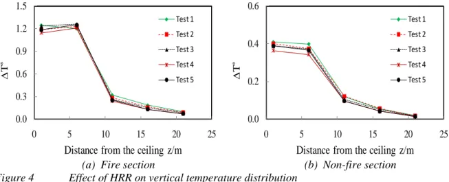
Figure 4 shows the vertical dimensionless temperature rise plotted against the distance from the ceiling for the five different fire sizes. Similar to the ceiling temperature distribution, Figure 4 shows that the vertical temperature distributions trends. Except for the thermocouple close to the ceiling, the dimensionless temperature did not change with the change in fire size.
(a) Fire section (b) Non-fire section
Figure 4 Effect of HRR on vertical temperature distribution
From the above analysis, the changes in the fire size (heat release rate) did not have significant effect on the dimensionless smoke temperature rise vertical and ceiling distributions.
Effect of shaft length on temperature distribution
Three shaft lengths were used to investigate the effect of the shaft length on the smoke diffusion characteristics. These were: 667 mm (Tests 5), 533 mm (Tests 6), and 800 mm (Tests 8) in length. The dimensionless temperature
∆
T
* defined in the previous sections was plotted against the distance from the fire source (Figure 5) and against the distance from the ceiling (Figure 6).The effect of the shaft length on the ceiling longitudinal temperature distributions is shown in Figure 5. It can be seen from Figure 5 that the dimensionless ceiling temperatures were almost the same in the fire section of the tunnel for the three shaft lengths. However, for a given distance from the fire source, the dimensionless ceiling temperature decreased with the increase in the shaft length in the non-fire section. This could be attributed to the longer shafts having the advantage of better extracting smoke while having insignificant effect on fire plume entrainment.
(a) Fire section (b) Non-fire section
Figure 5 Effect of shaft length on ceiling longitudinal temperature distribution
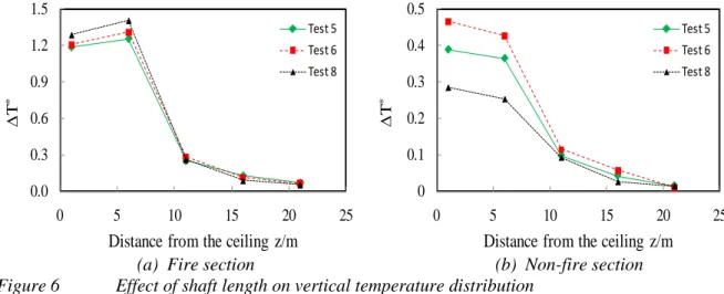
The effect of the shaft length on vertical temperature distributions is shown in Figure 6. The figure
0.0 0.3 0.6 0.9 1.2 1.5 0 5 10 15 20 25 ∆ T *
Distance from the ceiling z/m Test 1 Test 2 Test 3 Test 4 Test 5 0.0 0.2 0.4 0.6 0 5 10 15 20 25 ∆ T *
Distance from the ceiling z/m Test 1 Test 2 Test 3 Test 4 Test 5 0 1 2 3 4 5 6 7 0 0.5 1 1.5 2 ∆ T *
Distance from fire source x/m Test 5 Test 6 Test 8 0 0.1 0.2 0.3 0.4 0.5 0.6 0.7 2 4 6 8 ∆ T *
Distance from fire source x/m Test 5 Test 6 Test 8
shows that the shaft length has a similar effect on the vertical temperature distribution as its effect on the ceiling longitudinal temperature.
(a) Fire section (b) Non-fire section
Figure 6 Effect of shaft length on vertical temperature distribution
Effect of shaft height on temperature distribution
The effect of the shaft height on the ceiling longitudinal temperature and vertical distributions are shown in Figures 7 and 8. Three shaft heights were investigated: 267 mm (Tests 5), 133 mm (Test 10), and 400 mm (Test 12).
Figure 7 shows that the shaft height had the same effect on the ceiling longitudinal temperature distribution as that of the shaft length both for the fire and non-fire sections. The increase in the shaft height improved the efficiency of smoke extraction due to the increase in pressure difference across the height of the shaft.
(a) Fire section (b) Non-fire section
Figure 7 Effect of shaft height on ceiling longitudinal temperature distribution
The effect of the shaft height on vertical temperature distributions is shown in Figure 8. From the figure, it can be observed that the shaft height has the same effect on the vertical temperature as the effect on the longitudinal temperature. Comparing the two figures, Figure 6 and Figure 8, shows that increasing the shaft length had more effect in reducing the vertical temperatures than that due to the increase in the height of the shaft. This is true, especially, for points close to the ceiling (in the smoke layer). As such, the changes in the shaft length are more effective in extracting hot smoke and reducing the temperature in the tunnel than changes in the height of the shaft.
0.0 0.3 0.6 0.9 1.2 1.5 0 5 10 15 20 25 ∆ T *
Distance from the ceiling z/m Test 5 Test 6 Test 8 0 0.1 0.2 0.3 0.4 0.5 0 5 10 15 20 25 ∆ T *
Distance from the ceiling z/m Test 5 Test 6 Test 8 0 1 2 3 4 5 6 7 0 0.5 1 1.5 2 ∆ T *
Distance from fire source x/m Test 5 Test 10 Test 12 0 0.1 0.2 0.3 0.4 0.5 0.6 2 4 6 8 ∆ T *
Distance from fire source x/m Test 5 Test 10 Test 12
(a) Fire section (b) Non-fire section Figure 8 Effect of shaft height on vertical temperature distribution
Longitudinal temperature decays
Karlsson and Quintiere [10] used the one-dimensional smoke diffusion theory to develop the following formula for the determination of the longitudinal temperature decay, ∆Tx, in terms of reference temperature, ∆Tref , the distance from a reference point, x, and a constant value for a specific tunnel, α:
x x ref
T
T e
−α∆ = ∆
(5) In order to ensure the proper application of Eq. 5, it is critical to select a reference temperature at a tunnel section at which the temperature is homogenous and can be treated as a one dimensional problem. In this paper, the ceiling temperature at a distance from the fire source of 0.6 m was selected as the reference temperature,∆Tref , to investigate the longitudinal temperature decay characteristics. As the smoke was extracted through the first ventilation shaft, the temperature of the smoke sharply decreased. As such, Eq. 5 cannot be directly used at and right after the first shaft. Another reference temperature, ∆Tnref, should then be defined in order to investigate the temperature decays in the non-fire section after the first shaft. The ceiling temperature at a distance of 2.8 m from the non-fire source was selected as the reference temperature ∆Tnrefof the fire section. The temperature decays in non-fire section can be expressed as:x x nref
T
T
e
−β∆ = ∆
(6) where β is a constant of the temperature decay in the non-fire section just after the first shaft. From Eq. 3, the reference temperature in the fire section can be expressed as:*2/3 0
ref
T
aQ
T
∆
=
(7) From the analysis of the experimental data, the value of the coefficient a is about 1.68. Combining Eq. 5 and Eq. 7, the longitudinal ceiling temperature decay can be determined as follows:*2/3 0 x x T aQ T e−α ∆ = (8) If the effect of the shaft on the ceiling temperature was to be ignored, the reference temperature at the
0.0 0.3 0.6 0.9 1.2 1.5 0 5 10 15 20 25 ∆ T *
Distance from the ceiling z/m Test 5 Test 10 Test 12 0 0.1 0.2 0.3 0.4 0.5 0 5 10 15 20 25 ∆ T *
Distance from the ceiling z/m Test 5 Test 10 Test 12
non-fire section can be expressed as
∆
T e
ref −α(2.8 0.6)− . Considering the effect of the shaft, the reference temperature, ∆Tdref, can be determined from:(2.8 0.6)
dref ref nref
T
T e
−α −T
∆
= ∆
− ∆
=
(9) =ae-α(2.8-0.6)Q
*2/3T
o-bl
mh
nQ
*2/3T
owhere b, m and n are constants; l and h are the length and height of the shaft, respectively. Eq. 9 will result in the temperature difference ∆Tnrefto be zero, when shaft length and height equal 0 (no shaft case).
From the experimental data analysis, the constants; b, m and n were determined to be: 4 7,
2 3 and
1 3, respectively. Therefore, the smoke temperature decay along the tunnel ceiling in the non-fire section can be expressed as follows:
(2.8 0.6) 2/3 0 ( m n) x x T ae−α − bl h Q∗ T e−β ∆ = − (10)
Summary of the ceiling longitudinal temperature
The distance from the fire source can be used to replace the distance from the reference position. As such, the smoke temperature distributions along the tunnel ceiling for tunnel fires with natural ventilation can be expressed as:
*2/3 ( 0.6)
0
x x
T aQ T e−α −
∆ = for fire section (11)
(2.8 0.6) 2/3 ( 2.8)
0
( m n) x
x
T ae−α − bl h Q∗ T e−β −
∆ = − for non-fire section (12)
Eq.11 and Eq.12 can be re-written in a non-dimensional form as follows:
' *2/3 0.6 0 x x
T
T
aQ
T e
α∆
∆
=
for fire section (13)
=
e
−αxand ' (2.8 0.6) 2/3 2.8 0
(
)
x x m nT
T
ae
−α −bl h Q
∗T e
β∆
∆
=
−
for non-fire section (14)
x
e
−β=
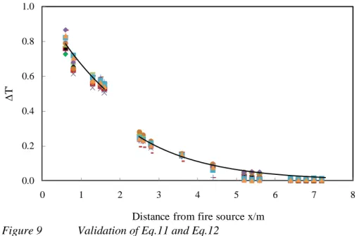
The experimental data of all tests and the prediction of the developed formulas of equations 11 and 12 are summarized and plotted in Figure 9. It is found that the longitudinal smoke temperatures can be well correlated with the equation.
Figure 9 Validation of Eq.11 and Eq.12
CONCLUSIONS
In this paper, the scale model experiments were carried out to investigate the tunnel fires with natural ventilation. Based on the fire plume theory, a dimensionless temperature
∆
T
*was defined to predict the temperature distributions in the tunnel.From the experimental data, the change in the fire size, for a fixed shaft size, does not have significant effect on the dimensionless temperature distributions in the tunnel. Moreover, the shaft size has no effect on the dimensionless temperature distributions in the fire section. However, the decrease in the shaft length or height will cause an increase of the dimensionless temperature in the non-fire section. Based on the one-dimensional theory and using two different reference temperatures, the ceiling temperature decay can be expressed as exponential functions of the distance from a reference location for the two regions, the fire section and the non-fire section.
REFERENCE
1. Kunsch, J.P. “Simple model for control of fire gases in a ventilated tunnel”, Fire Safety Journal,
37 (1), 67-81, 2002.
2. Hu, L.H., Huo, R., and Chow, W.K. “Studies on buoyancy-driven back-layering flow in tunnel fires”, Experimental Thermal and Fluid Science, 32 (8), 1468-1483, 2008.
3. Vauquelin, O. “Parametrical study of the back flow occurrence in case of a buoyant release into a rectangular channel”, Experimental Thermal and Fluid Science, 29 (6), 725-731, 2005.
4. Li, Y., Lei, B., and Haukur, I. “Study of critical velocity and backlayering length in longitudinally ventilated tunnel fires”, Fire Safety Journal, 45 (6-8), 361-370, 2010.
5. Carvel, R.O., Beard, A.N., and Jowitt, P.W. “The influence of longitudinal ventilation systems on fires in tunnels”, Tunnelling and Underground Space Technology, 16 (1), 3-21, 2001.
6. Yuan, Z., Lei, B., and Chen, P. “Experimental study of tunnel fires with natural ventilation”,
Journal of Hunan University, 36 (5) 23-25, 2009.
7. Yuan, Z., Lei, B., and Chen, P. “Numerical simulation of fire smoke flow characteristics in subway tunnel with natural ventilation”, International Conference on Transportation Engineering, Chengdu, 2009.
8. Wang, Y., Jiang, J., and Zhu, D. “Full-scale experiment research and theoretical study for fires in tunnels with roof openings”, Fire Safety Journal, 44 (3), 339-348, 2009.
9. Wang, Y., Jiang, J., and Zhu, D. “Diesel oil pool fire characteristic under natural ventilation conditions in tunnels with roof openings”, Journal of Hazardous Materials, 166 (1), 469-477, 2009. 10. Karlsson, B., Quintiere, J.G. “Enclosure Fire Dynamics”, CRC Press, 2000.
0.0 0.2 0.4 0.6 0.8 1.0 0 1 2 3 4 5 6 7 8 ∆ T '