Publisher’s version / Version de l'éditeur:
Vous avez des questions? Nous pouvons vous aider. Pour communiquer directement avec un auteur, consultez la première page de la revue dans laquelle son article a été publié afin de trouver ses coordonnées. Si vous n’arrivez pas à les repérer, communiquez avec nous à PublicationsArchive-ArchivesPublications@nrc-cnrc.gc.ca.
Questions? Contact the NRC Publications Archive team at
PublicationsArchive-ArchivesPublications@nrc-cnrc.gc.ca. If you wish to email the authors directly, please see the first page of the publication for their contact information.
https://publications-cnrc.canada.ca/fra/droits
L’accès à ce site Web et l’utilisation de son contenu sont assujettis aux conditions présentées dans le site LISEZ CES CONDITIONS ATTENTIVEMENT AVANT D’UTILISER CE SITE WEB.
14th Asian-Pacific Corrosion Control Conference [Proceedings], pp. 1-6,
2006-10-21
READ THESE TERMS AND CONDITIONS CAREFULLY BEFORE USING THIS WEBSITE.
https://nrc-publications.canada.ca/eng/copyright
NRC Publications Archive Record / Notice des Archives des publications du CNRC :
https://nrc-publications.canada.ca/eng/view/object/?id=6151cd7b-eeb2-4ff4-a807-1fd6a439d743 https://publications-cnrc.canada.ca/fra/voir/objet/?id=6151cd7b-eeb2-4ff4-a807-1fd6a439d743
NRC Publications Archive
Archives des publications du CNRC
This publication could be one of several versions: author’s original, accepted manuscript or the publisher’s version. / La version de cette publication peut être l’une des suivantes : la version prépublication de l’auteur, la version acceptée du manuscrit ou la version de l’éditeur.
Access and use of this website and the material on it are subject to the Terms and Conditions set forth at
Galvanic effect induced by coupling of stainless steel and carbon steel
reinforcements
http://irc.nrc-cnrc.gc.ca
Ga lva nic e ffe c t induc e d by c oupling of
st a inle ss st e e l a nd c a rbon st e e l
re inforc e m e nt s
N R C C - 4 9 2 2 6
Q i a n , S . ; Q u , D .
A v e r s i o n o f t h i s d o c u m e n t i s p u b l i s h e d i n
/ U n e v e r s i o n d e c e d o c u m e n t s e t r o u v e
d a n s : 1 4
t hA s i a n - P a c i f i c C o r r o s i o n C o n t r o l
C o n f e r e n c e , S h a n g h a i , C h i n a , O c t . 2 1 - 2 4 ,
2 0 0 6 , p p . 1 - 6
Galvanic Effect Induced by Coupling of Stainless Steel
and Carbon Steel Reinforcements
∗Shiyuan Qian 1 and Deyu Qu2 1
Institute for Research in Construction, National Research Council Canada Ottawa, Ontario, Canada, K1A 0R6
2 Physical Chemistry Laboratory, Division of Chemistry, Graduate School of Science
Hokkaido University, Sapporo, Japan
Abstract: A cost-effective approach that has the potential to extend the service life and reduce maintenance costs of concrete structures is to use stainless steel rebar in high corrosion risk areas, combined with carbon steel rebar in low-risk areas. However, concerns about galvanic corrosion associated with the use of two different metals in direct (electrical) contact prevented the application of this design approach. This paper investigates the galvanic coupling behaviours of carbon steel and three different stainless steels (304 LN, 316LN and 2205). Tests were performed using both electrochemical cells and specimen-containing concrete blocks. The polarization curves and cyclic voltammograms of carbon and stainless steels, as well as the galvanic coupling behaviours of the steels are presented. The results indicate that the oxygen reduction reaction is the rate-determining step and is much lower on stainless steel than on passive carbon steel. Therefore, the galvanic coupling current between stainless steel and corroding carbon steel is lower than the coupling current between passive and corroding carbon steels. Consequently, the use of stainless steel with carbon steel rebars will not increase the risk of corrosion of carbon steel rebar.
Keywords: galvanic coupling; carbon steel; stainless steel; reinforcement corrosion; chloride.
1. Introduction
Corrosion is the main cause of deterioration of conventional carbon-steel-reinforced concrete structures. Stainless steel has been used to minimize the problems of reinforcement corrosion in many concrete structures in the last 20 years. However, the use of this reinforcement is still limited, partially because of its higher initial cost. Therefore, a potentially economical approach is to use stainless steel only in areas with a high risk of corrosion. There have been concerns about galvanic corrosion, as these dissimilar metals will be in direct (electrical) contact in concrete structures. Consequently, engineers are often hesitant to use stainless steel and carbon steel in the same concrete structure.
Limited investigations have been carried out and published, but the results and conclusions are controversial. Bertolini et al. (1) and Klinghoffer et al. (2) suggested that the use of carbon steel with stainless steel does not increase the risk of corrosion for the carbon steel, as long as both metals are in a passive condition. However, Webster (3) and Seibert (4) stated that corrosion could initiate if two different metals were electrically connected and suggested to isolate carbon steel and stainless steel.
This paper presents an investigation of the galvanic coupling behaviour between carbon steel (CS) and three types of stainless steel (SS) alloys. Tests were performed both in electrochemical cells containing saturated calcium hydroxide [Ca(OH)2] solution and with concrete specimens
inside an environmental chamber. Sodium chloride (NaCl) was introduced to the solution during the experiment or premixed in the concrete to simulate aggressive environmental conditions from road salt in the field. The galvanic coupling currents between corroding CS and SS were measured and compared with those between corroding CS and passive CS, which always surrounds the corroding area. The anodic/cathodic behaviours of individual CS and SS were also studied using the potential polarization test and cyclic voltammetry. The effects of the
∗
oxygen reduction rate, coupling resistance and chloride content on the galvanic coupling current were also investigated.
2. Experimental
The electrodes were machined from reinforcing CS and SS bars (2205, 304LN and 316LN). The samples were connected by steel rods as the electric conductor and then embedded in epoxy resin leaving a fixed steel surface (0.7 cm2 and 28.6 cm2) exposed to the solution. The samples were polished with #600 silicon-carbide papers and then immersed in saturated Ca(OH)2
solution with a pH of 12.6 for a week. The corroding CS samples were prepared by placing them in a humidity room to let the rust accumulate on their surfaces.
The electrochemical experiments were carried out in a saturated Ca(OH)2 solution or a saturated
Ca(OH)2 + 3% NaCl solution. De-ionized water (≥18.3 MΩ cm2, Milli-Q) was used to prepare
the solution and high-purity argon and oxygen were used in some experiments to respectively purge or dissolve oxygen in the solution.
Concrete specimens were made of ordinary Portland cement with a 0.5 w/c ratio. Two rebars were embedded in parallel in concrete specimens. Different amounts of NaCl were added to the concrete mixtures. In each specimen, two ends of the rebar were coated with epoxy resin and covered by a shrinkable sleeve leaving a length of 15 cm (surface area ≈70.7 cm2) exposed to
the concrete.
Electrochemical techniques such as cyclic voltammetry, linear polarization, potential dynamic and galvanic coupling were used in this study. All tests (except the galvanic coupling experiment) were conducted in three-compartment electrochemical cells. The working electrode was the CS or SS sample. The counter electrode was made of platinum foil or mesh. The reference electrode was a saturated calomel electrode (SCE). The measurements were carried out using a Solartron 1480 multistat or a Solartron SI 1287 electrochemical interface, which was controlled by a PC using Corr-Ware software.
The galvanic coupling experiments were carried out using a setup of two cells connected by a salt bridge or the steels embedded in concrete specimens. The specimens were located in an environmental chamber with high relative humidity and cycled temperature to accelerate the rebar corrosion. The galvanic current was measured and recorded by connecting the two metals using a Keithley 485 picoammeter controlled by a PC using VEE pro software.
3. Results and Discussion
3.1 Galvanic Coupling Current Density
The galvanic coupling current densities, Igc, measured by connecting corroding CS with passive
CS or SS (2205, 304LN and 316LN) are shown in Figure 1. It can be clearly seen that the Igc
between the corroding CS and SS is less than half of that between the corroding CS and the passive CS.
The corrosion rate of the corroding CS was measured using a linear polarization technique. The average rate was 13.3 ± 0.4 µA/cm2 at a corrosion potential of –0.6 V vs SCE. The percentage
increases in Icorr due to the coupling of the corroding CS and the passive CS or SS over the
corroding CS are listed in Table1. It is known that Igc does not fully contribute to an increase in
the corrosion of the corroding CS. It compensates partially (about 40% of Igc) for the decrease in
the cathodic current density and contributes partially (about 60%) to the increase in the corrosion current density, ∆Icorr, on the corroding CS. These values are calculated based on the
experimental results showing that the Tafel slopes of anodic and cathodic polarization for corroding CS are 40 mV and 60 mV, respectively. Therefore, the increase in the corrosion rate
is about 2.4% due to the galvanic coupling between the corroding CS and passive CS, and it is only about 1.0% due to the galvanic coupling between the corroding CS and SS.
Table 1. Ratio of Igc to Icorr for various
metals coupled with corroding CS at –0.6 V.
Metals Igc/Icorr (%) ∆Icorr/Icorr (%)
Passive CS 4.0 2.4
SS 2205 1.7 1.0
SS 304LN 1.7 1.0
SS 316LN 1.8 1.1
Note: Igc is the average measured value.
Fig. 1. Igc measured in saturated Ca(OH)2 solution.
3.2 Effect of Oxygen on Cathodic–Reduction Current
The cyclic voltammograms of passive CS and SS 2205, 304LN and 316 LN were measured in the saturated Ca(OH)2 solution as shown in Figure 2. The cathodic and anodic current densities
of all SS alloys are significantly smaller than those of the passive CS. The corrosion potential of the corroding CS is about −0.55 V to –0.6 V. Therefore, the potential of galvanic coupling of corroding CS with passive CS or SS should be in this potential range, and the reactions on passive CS or SS are cathodic. From the inset of Figure 2, it can be seen that the cathodic reduction current densities of all SS alloys are much smaller than those of the passive CS (solid line). Obviously, the surface of SS does not favour the process of cathodic reduction.
Fig. 2. Cyclic voltammograms of passive CS and SS measured in a saturated Ca(OH)2 solution (the inset shows an enlarged current scale).
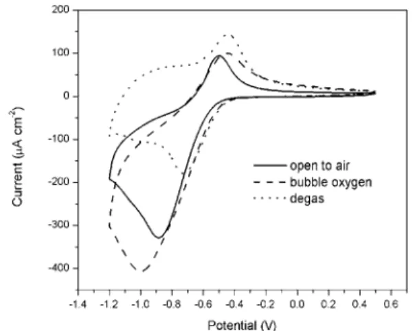
The effect of dissolved oxygen on the cathodic reduction current density was investigated. First, a cyclic voltammogram of passive CS was measured in a cell open to the air. Oxygen was then bubbled into the cell to saturate the electrolyte solution, and another cyclic voltammogram was measured. Afterwards, the solution in the cell was degassed by bubbling argon into the cell to remove the dissolved oxygen. The cyclic voltammogram was measured again. The cyclic voltammograms measured under these three conditions are shown in Figure 3. The cathodic
current had the smallest peak with a value of −180 µA/cm2 at −0.72 V when oxygen was purged
from the solution. The charges for the cathodic and anodic scans are almost equal indicating that both reactions are mainly for the electrode surface oxidation and reduction. When the concentration of oxygen in the solution was increased (cell open to the air), the cathodic current peak increased to −330 µA/cm2 at −0.87 V. When the electrolyte solution was saturated with
oxygen, the cathodic current peak increased to the largest value of −400 µA/cm2 at −1.0 V
indicating that a significant oxygen reduction reaction was involved.
In the potential region between −0.4 V and −0.72 V, the effect of oxygen concentration on the cathodic reaction was not observed, because the reduction of the oxidized metal surface dominated the reaction. The slight increase in the reduction currents under the conditions of bubbling oxygen and argon is probably caused by the increase in the diffusion process due to gas bubbling through the solution. In the anodic scan (from −1.2 V to −0.4 V), the current shifts to more negative values when open to air and bubbling oxygen, because of the process of continuing oxygen reduction. The current increase in the more positive region (−0.4 V to +0.5 V) is due to the bubbling effect causing the increase in the diffusion process.
Figure 4 shows the cathodic polarization curves of the passive CS and the SS. The cathodic current densities on the three SS alloys are all much smaller than those in the passive CS in the range of −0.5 V to −0.6 V. As described above, Igc is limited by the cathodic reduction reaction
on the passive CS or SS when the corroding CS is coupled with them. Therefore Igc induced by
SS is much smaller than that induced by the passive CS when these metals are coupled with corroding CS.
Fig. 4. Polarization curves of passive CS and SS in saturated Ca(OH)2 solution.
Fig. 3. Cyclic voltammograms of passive CS under various oxygen conditions.
3.3
Effect of Chloride IonsSince SS has a much higher threshold of resistance to chloride-corrosion, it can be substituted for CS in critical areas with high concentration of chloride ions in order to extend the service life of concrete structures. The effect of SS surrounded by chloride ions on the galvanic coupling current is another important factor to evaluate in determining whether coupling CS with SS is a safe design approach in such environments.
The galvanic-coupling current was investigated by coupling corroding CS with SS in a saturated Ca(OH)2 solution containing 3% NaCl, as shown in Figure 5 (inset). The average values of Igc
were 0.42 µA/cm2, 0.33 µA/cm2 and 0.23 µA/cm2 for SS 2205, 304LN and 316LN, respectively. The curve of Igc for passive CS coupled with corroding CS in a 3% NaCl solution was measured
shown in Figure 5. As a result, the corrosion of the passive electrode could be delayed or reduced since it was cathodically protected by the corroding electrode. It is shown that the value of Igc obtained on passive CS coupled with corroding CS was very high and reached a stable
value at a slower rate in the presence of 3% NaCl.
Fig. 5. Igc measured by coupling corroding CS with passive CS or SS alloys
in a saturated Ca(OH)2 solution containing 0% or 3% NaCl.
3.4 Galvanic Coupling Test in Concrete Specimens
The galvanic currents of active CS coupled with passive CS or SS in either chloride-free concrete or in concrete containing 3.5% chloride ions were investigated. In both cases, the active CS was cast in concrete containing 1.5% chloride ions. After the two rebars were connected, the coupling potential was about –0.15 V and the Igc values were relatively low
(about a few nA/cm2) over 220 days indicating no considerable galvanic coupling current, even though the CS was in the concrete containing 1.5% chloride ions. After 220 days, the coupling potential shifted to more negative values (about −0.25 V to −0.35 V) and Igc was dramatically
increased to around 150 nA/cm2 for SS 2205 and 75 nA/cm2 forSS 304LN and 316LN (with some delay for SS 304LN). The values of Igc decreased gradually to about 30, 26 and 15 nA/cm2
for SS 2205, 304LN and 316LN, respectively, after about 380 days. This was probably due to the formation of cracks in the concrete near the corroding CS rebars.
When SS was subjected to 3.5% chloride ions, the change in coupling potential with time was similar to that in chloride free concrete. After being coupled for about 220 days, the coupling potential began to shift to < −0.3 V, and Igc increased from 5 nA/cm2 to 80, 120 and 200 nA/cm2
for SS 2205, 304LN and 316LN, respectively. Then the Igc gradually decreased to around 40
nA/cm2. The Igc was slightly higher with SS in concrete containing 3.5% chloride ions than in a
chloride-free environment. This may have been caused by two factors: the effect of chlorides on the cathodic reduction reaction on SS or the reduced resistance due to the presence of 3.5% chloride ions in the sides of the specimen in which the stainless steels were embedded.
The galvanic coupling potential and the Igc measured from the active CS (1.5% chloride ions)
coupled with the passive CS (chloride-free concrete) are shown in Figure 6. After 275 days, the coupling potential shifted to −0.4 V, and the coupling current density increased rapidly to 800 nA/cm2 then decreased to about 150 nA/cm2 due to concrete cracking near the rebars. It was clearly shown that the Igc between active and passive carbon steels was much higher than that
between active CS and SS, even when the SS was in concrete containing 3.5% chloride ions. This result is in good agreement with that obtained in the saturated Ca(OH)2 solution in the
-500 -400 -300 -200 -100 0 100 200 300 400 -100 0 100 200 300 400 500 600 700 Time (day) Potential (mV vs SCE) -800 -600 -400 -200 0 200 400 600 800 1000 I gc (nA/cm 2 ) Passive CS Active CS
Fig. 6. Galvanic coupling potentials and Igcmeasured in concrete specimens for
CS in 1.5% Cl- coupled with passive CS in chloride-free environment.
4. Conclusions
The use of stainless steel and carbon steel reinforcing bars in direct contact in concrete structures will not increase the corrosion risk on CS. In fact, the increase in the corrosion rate of CS due to galvanic coupling of SS with corroding CS was less than that of the combination of non-corroded CS with corroding CS. Stainless steel, with its ability to resist chloride-induced corrosion, can be used in areas vulnerable to chloride ingress. Therefore, the judicious use of stainless steel with carbon steel in the high-corrosion-risk areas of a concrete structure can be a cost-effective option for reducing corrosion and extending the service life of concrete structures. In the presence of 3% NaCl, the Igc induced by SS 2205 and 304LN increased due to an increase
in the cathodic reduction reaction when they were exposed to chloride ions. However, the Igc
induced by SS 316LN remained almost unchanged indicating that this type of SS performs better regarding the galvanic coupling effect in concrete containing chloride.
The galvanic coupling tests carried out in the concrete specimens confirmed the laboratory experimental results. When SS reinforcing bars were coupled with corroding CS bars, the Igc
was much smaller than that in a coupling between passive and corroding CS reinforcement.
5. Acknowledgments
Grateful acknowledgment is made to The Nickel Institute, Alberta Transportation, City of Ottawa, Ministère des Transports du Québec and Valbruna Canada Ltd. for their contributions and support for this research project. Thanks are also due to Bruce Baldock, Glendon Pye, Gordon Chan and Bob Myers of IRC/NRC for their help with the research work.
6. References
[1] L.Bertolini, P.Pedeferri, Corrosion Review, 2002, 20, 129.
[2] O.Klinghoffer, T.Frolund, B.Kofoed, A.Knudsen, F.Jensen, et al., Corrosion of Reinforcement in Concrete, J.Mietz, R.Polder, and B.Elsener, Editors, London, 2000, 121. [3] H.Webster, COR-97-7810-N, Correng Consulting Service Inc., Downsview, Ontario, 1997. [4] P.Seibert, M. Sc Thesis, Queen's University, 1998.