To link to this article: DOI:
10.3233/ICA-150494
http://dx.doi.org/0.3233/ICA-150494
This is an author-deposited version published in:
http://oatao.univ-toulouse.fr/
Eprints ID: 17389
To cite this version:
Vareilles, Elise and Coudert, Thierry and Aldanondo, Michel and Geneste,
Laurent and Abeille, Joël System design and project planning: Model and
rules to manage their interactions. (2015) Integrated Computer-Aided
Engineering, vol. 22 (n°4). pp. 327-342. ISSN
1069-2509
O
pen
A
rchive
T
oulouse
A
rchive
O
uverte (
OATAO
)
OATAO is an open access repository that collects the work of Toulouse researchers and
makes it freely available over the web where possible.
Any correspondence concerning this service should be sent to the repository
administrator:
[email protected]
System Design and Project Planning:
model and rules to manage their interactions
Elise Vareilles
a,∗, Thierry Coudert
b, Michel Aldanondo
a, Laurent Geneste
band Joel Abeille
c aUniversity of Toulouse - Mines Albi, route de Teillet Campus Jarlard, 81000 Albi cedex 09 FranceE-mail: [email protected]
bUniversity of Toulouse - ENIT, 47 avenue d’Azereix, 65000 Tarbes France,
E-mail: [email protected]
cPulsar Innovation, Colomiers France,
E-mail: [email protected]
Abstract.This article proposes a model and rules dealing with the management of the interaction between system design processes and project planning ones. An industrial benchmark analysis has reinforced our belief that the interaction between the two processes has to be supported by models, processes and relevant tools. Firstly, after presenting the results of the analysis, the different entities are defined and the one-to-one relationship or bijection between the structure of the system and the structure of the project is made. Then, a model, taking into account design activities and planning activities as well as management of interactions, is proposed in compliance with existing project and design standards. A process of interaction is presented to carry out design and project management. Two interaction modes have been proposed. On the one hand, the structural interaction establishes links between entities of the two domains. On the other hand, the behavioral interaction (subject of this paper) is based on the definition of states for each entity following feasibility and verification criteria, and can thus manage the changes between states. Some rules are defined (precedence and synchronous rules) to forbid certain changes when they are inconsistent and to synchronize them.
Keywords: System Design, Project Planning, Aiding Decisions, Knowledge based Systems
1. Introduction
Because of the increasing complexity of products, the considerable reduction of products time-to-market and de facto, the dwindling of design time without af-fecting product quality and innovation, today’s product and system design processes have to interact more and more closely with all other business processes in a com-pany, such as procurement process, production process, assembly process, maintenance process, etc ([27] and [28]).
In such a context, the building of design activities, from requirement expression to solution design, and the planning and control of these activities, are important tasks ([5] and [25]). Therefore, the interactions between
*Corresponding author. E-mail: [email protected]
the design of a system and the building of its design project are crucial and have to be formalized and mon-itored in order to avoid inconsistencies between these two processes.
Recent project failures (A380 Program, Olkiluoto Nuclear Power Plant) have highlighted the fact that the management of system design, project planning and their interactions, is critical. Much interdisciplinary and concurrent work as well as better communication be-tween the design side and the project side are there-fore required ([21] and [33]). Co-operation and interac-tions across engineering teams and project managers are vital to the planning process and the success of the project in terms of quality, delay and cost ([7] and [43]). This statement is true whatever the complexity of the designed system and the stage of its development.
However, few studies have focused on the manage-ment of interactions between design process and plan-ning process or have proposed models and tools that can assist engineers and managers in the task of building design projects in accordance with the design of sys-tems, in planning the design activities, and especially in controlling their execution ([5] and [26]).
In [1], the structural interaction linking system de-sign and project planning and the meta-model support-ing this kind of interaction have been described. This structural interaction relies on a one-to-one or bijective link between system and project structures.
In this article, a focus is made on the behavioral
interactionthat allows these two processes to be syn-chronized, through two specific attributes and nine precedence and coupling rules. Behavioral coupling en-sures monitoring and the control of the system design and project planning by imposing synchronous mile-stones during project development. This synchroniza-tion forces engineers and managers to be aware of the situation of the other side, and to take it into account in their own process. Consequently, they can decide together, considering the overall situation, whether to modify some or all of their requirements to reach the project goals under suitable conditions. Behavioral in-teraction has to be directed regardless of the stage of the design and planning processes, regardless of the system and project complexities, and regardless of the type of companies.
We have to stress that our proposal is rather prag-matic and easily conceivable and may belong to every-one’s experience and common sense. However, to the best of our knowledge, only a couple of scientific pa-pers have made explicit this kind of interaction between design and planning ([20], [5]), but neither has formal-ized them. We introduce the term of coupling to denote the identified interactions (structural and behavioral) between the two processes as well as their management. By formalizing such aided interactions we make it pos-sible to integrate them into a PLM (Product Lifecycle Management) software.
The remainder of the article is organized as follows: in Section2, the context of the study is described. In Section3, the background is defined and the structural coupling proposed in [1] is synthesized with regard to existing approaches. In Section4, we focus on syn-chronous coupling and we introduce and define the spe-cific attributes used in behavioral interaction. In Sec-tion5, the rules, based on the specific attributes, are defined in order to forbid certain changes when they are inconsistent and to synchronize the two processes.
In Section6, a real-life engineering example, designed with a sample of companies, illustrates our proposals.
2. Context of the Study
The need for interaction between engineers and man-agers has been consolidated by interviewing fifteen experienced project managers from different compa-nies belonging to the world competitiveness cluster, Aerospace Valley1. Out of the 10 sample companies, 11% were very small enterprises, 22 % were small or medium enterprises, and 67% were large companies.
The most important results can be summarized as follows:
– All the companies interviewed are confronted with this coupling problem but they have not imple-mented specific tools to support this coupling pro-cess. Only 18% of companies use software or col-laborative tools.
– Half of the companies make decisions taking into account design and planning as well as their in-teractions, during meetings involving the different stakeholders.
– Most of the time (66%), the coupling is performed by means of non-formalized human interactions. Even if companies use software, procedures or standards (45%), their decisions are based on hu-man experience and meetings.
Meanwhile, the complexity of systems and projects is increasing. In a multi-national context, the design of a system is often carried out in several sites involving several partners. In such a context, human-based pro-cedure is no longer sufficient enough to detect prob-lems as early as possible, to analyse information and data, or to react correctly to the situation. Design cycles are more and more reduced and the slightest error in the design or planning sides can jeopardize the success of the whole project. Clearly, the use of adapted and interconnected tools, supporting multi-responsibility projects, for managing these complex design projects is becoming a requirement in such contexts ([21] and [27]). PLM software is designed to help organizations in coping with the increasing complexity and engineer-ing challenges of developengineer-ing new products [18]. The proposed structural and behavioral couplings easily fit PLM functionalities. Furthermore, they can be added,
without any difficulty, to PLM software without modify-ing users’ habits or the PLM software process. This can extend the scope of their functionalities by imposing a specific structure for systems and projects, and regular synchronous milestones for engineers and managers.
To illustrate the global context of this study, a project (associated with a system that needs to be designed) is considered to be under the responsibility of a program manager, i.e. the highest person in the hierarchy. The program manager interacts with (i) a design manager who works within a design system environment and (ii) a planning manager who works within a project plan-ning environment. The difficulty involved in desigplan-ning the system, as well as the complexity of the associated project, leads to them being hierarchically decomposed according to the axiomatic design approach [42], [35], [2].
In such cases, systems can be decomposed into sub-systems, leading to the decomposition of associated development projects into associated sub-projects. The corollary is that complex design projects can be decom-posed into sub-projects leading to the decomposition of the system in the same manner. Therefore, at each level of the hierarchy, the interactions can be observed. In this context, the program manager, at his/her level, can be seen as a "coupling manager" who fixes orienta-tions and objectives, makes decisions and defines deci-sion parameters for the two other parts. (S)he is also in charge of resolving conflicts.
Within this framework, considering two hierarchical levels, either the design manager of the upper level becomes the program manager of the lower level, or it is the planning manager who takes on this role. This outcome varies from company to company. It is also possible, in some cases at the lowest levels, to have only one person in charge of the three responsibilities.
3. Background and Proposals
In this section, the background of our work is de-fined and the structural coupling is synthesized with regard to existing approaches. In Subsection3.1, after reviewing design process definitions, we define what we mean by system design in this paper. In Subsection
3.2, after reviewing planning process definitions, we define what we mean by project planning. Then in Sub-section3.3, after a literature review of interactions be-tween design and project processes, structural coupling is synthesized.
3.1. System Design Process
H. A. Simon [30] first characterized design as a search process. Design can be seen as a project that aims to create a new object or to transform an existing one [16]. Design is also considered to be a knowledge discovery process in which information and knowledge of diverse sources are shared and processed simultane-ously by a team of designers involved in the life phases of a product [37], [41]. There are many existing design methodologies described in the literature (see, for in-stance, the methodologies described in [6], [24], [35], [38], or for a wide panorama, [4]).
Among the widely used methodologies, Axiomatic Design (AD) proposed by Suh [35] is a top-down and iterative approach that makes links between require-ments or functions (functional requirerequire-ments) to be ful-filled and technical solutions (design parameters and process variables). The design process zigzags between the four following domains: needs, solutions, tasks and resources.
From a system engineering viewpoint, the works of the International Council on Systems Engineering (IN-COSE) have been considered in detail. Among them, the EIA-632 standard [23], [8] provides some structur-ing processes for system design broadly used by com-panies in the electronics domain. It defines a global engineering process that makes it possible to transform customer requirements into technical solutions.
Given these previous studies, the design process pro-posed in this article is structured as follows:
1. The definition and/or the specification of the re-quirements,
2. The identification of the technological solutions which can fulfill these requirements,
3. The matching of requirements and solutions, and 4. According to the complexity, the decomposition of the design process up to a certain level of ab-straction.
3.2. Project Planning Process
The project planning domain of our work concerns the Project Time Management (PTM) process as de-fined by the Project Management Institute [25]. In the proposed approach, the project planning definition is a top-down approach, where some kind of global plan-ning is achieved at a high level and is progressively detailed at lower levels by means of sub-projects. This multi-level and multi-project approach makes it
pos-sible to perform adequate multi-level planning by si-multaneously considering, at all planning levels, differ-ent objectives, constraints, degrees of aggregation, and capacity flexibility (see for instance [14] for a study on hierarchical multi-project planning). In order to de-fine a design project, we consider that project planning involves:
1. Project activities definition,
2. Resource and duration identification, 3. Scheduling activities and resources, and
4. If needed recursive decomposition at the lower level of some activities.
Scheduling of activities and resources is based on several techniques (see, for instance, [15] or [19]) that are not detailed in this article.
3.3. Design and Planning Processes Interactions
In this subsection, firstly, a literature review of inter-actions between design and project processes is carried out. Secondly, structural coupling, the basis of behav-ioral interaction, is synthesized.
3.3.1. State of the art
The axiomatic design and the above-mentioned stan-dards allow four interacting domains to be identified:
1. The requirements or specifications, 2. The design solutions,
3. The tasks or activities, and 4. The resources.
The first two domains relate to the system design process and the last two domains to the project planning process. Of the few studies that address this coupling problem, one can mention:
– The study of [20] explicated a link between PBS (Product Breakdown Structure) and WBS (Work Breakdown Structure). The author stated that the WBS tree (or structure) is derived from that of the PBS. The isomorphism of PBS and WBS trees is suggested. Other trees are introduced at the end of the paper, such as a specification tree and a drawing tree.
– The studies initialized at M.I.T. [9] on the use of methods and techniques used in product design in order to facilitate project design. These studies are the source of scientific developments around DSM (Design Structure Matrix), such as those of Lindemann [22] where the interactions between the four identified domains are defined .
– Simultaneously, axiomatic design identifies var-ious domains (Customer Needs, Functional Re-quirements, Design Parameters and Process Vari-ables) and sees them as interacting [36]. An ex-ample of implementation is presented in [13]. The interactions between domains are clearly defined: not only design towards planning but also planning towards design.
– Another approach, introduced by Gero [10], pro-poses models based on three domains: Function, Behavior and Structure (FBS). The aim of this study is to take into account product behavior (ex-pected and effective) and to inventory in a formal way eight sub-processes of design. However, tools for interactions between processes are not explic-itly considered.
– A study that is very close to the problem addressed was undertaken by Stewart and Tate [34] who were interested in the coupling of axiomatic design with project planning in the case of software engineer-ing. Their idea was to associate design variables with the tasks of the development process. This approach was implemented with an ad hoc devel-opment coupled with the Microsoft Project® soft-ware package and tested in a softsoft-ware engineering context.
– The work of R. Lu [28] describes an approach cou-pling task management and design. The structure of projects is represented by means of a Working Breakdown Structure (WBS) and is related to a Product Breakdown Structure (PBS). A matrix rep-resents the relationships between both domains. – In [31] and [32], the authors proposed a Project
Product Lifecycle Management approach (PPLM). The aim of their work is to develop a methodology and a software environment for integrating the product that is being developed with the project as undertaken by the company.
– In [5], the authors proposed a model to enable concurrent product design and assembly sequence planning. The aim of their work is to manage vi-tal yet complex and inherent product relationship information to allow such concurrent product de-sign and assembly sequence planning. This paper gives the detailed description of the background and models which highlight the need for a more efficient PLM approach.
– In [11], the authors consider that a design project, in mechanical system engineering, is a network of various interacting design domains such as project, product and process design. The paper presents
an object-oriented design methodology integrated into a human-based and co-operative design life cycle. This methodology was implemented in an educational web-based environment and applied to student design projects.
All these studies indeed confirm the four domains (requirements, solutions, tasks and resources) and the existence of causal links that engender interactions be-tween these four domains. However, except in [34], [11], [28] and [32], no tools are provided to support or aid interactions between both the design and planning processes.
3.3.2. Structural Coupling Synthesis
Structural coupling is based on a structural and hi-erarchical decomposition of systems into sub-systems and/or projects into sub-projects (guided by their intrin-sic complexity). Two coupled entities are then defined:
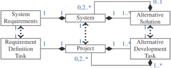
– A system entity is composed of one set of require-ments and one or more solutions (or system alter-natives), as shown in the upper part of Fig.1. – A project entity is composed of one task of
re-quirement definition and one or more tasks of so-lution design (or an alternative development task), as shown in the lower part of Fig.1.
It is important to preserve the semantic of the enti-ties of both domains without mixing the information. Indeed, designers and managers have to keep their re-spective autonomy of decision-making. Once a deci-sion is made on one side, they have to be informed of any negative impacts (or potential problems) on the other side. In such a case, the current situation should be resolved in a style of mediation: engineers and man-agers have to share their requirements, constraints and goals in order to react appropriately and ensure the suc-cess of the project. This mediation can be supported by the AHP method [29] in order to evaluate different solutions and select the one that best suits system and project requirements at the same time.
Furthermore, in this article we favor a progressive top-down design approach where projects and sub-systems are defined only when required and when their context is well known. For instance, the decision to subcontract the design of a particular sub-system can be taken only after a suitable requirement analysis and when these requirements have been compared with available resources. At this time, the choice of a sub-contractor and the definition of the required sub-project, as well as its characteristics and constraints, can be es-tablished. Therefore, a bijective link between the BOM
System Alternative Solution System Requirements 1..* 1 1 1 0,2..* 0..1 Project Alternative Development Task Requirement Definition Task 1..* 1 1 1 0,2..* 1..* 1 1 1 1 1 1
Fig. 1. Integrated Model of Structural Coupling
(Bill of Materials) of a system and the WBS (Work Breakdown Structure) of a project appears to be the only comprehensive solution.
This bijective link is fully compliant with the Ax-iomatic Design of Suh [35] and its zigzagging method-ology, with the work of R. Lu [28] which links PBS and WBS and their relationship with a matrix, and with the work of [31] and [32] who have proposed a Project Product Lifecycle Management approach (PPLM). In our proposal and as shown in Fig.1, we link also in a bijective way and at any level in the hierarchy:
– A system S and a project P,
– The set of system requirements SR and the require-ment definition task PR,
– A system alternative SA and an alternative devel-opment task PA.
These entities are the foundations of structural and behavioral couplings (see [1], [3], [39] and [40] for an overview of the meta-model supporting structural coupling).
Regarding industrial benchmark results, the coupling between system design and project planning processes does not only draw bijective links between system and project entities. Structural coupling ensures an isomor-phism between system and project structures, but this is not sufficient to manage all their interactions. Managers also need to synchronize the two processes in order to plan and monitor the complete system design project. This synchronization is the main goal of the paper. Our proposal is quite original:
– Firstly, the monitoring is done through two spe-cific attributes which qualify the feasibility and the verification of system and project entities, – Secondly, these two attributes foster the control
of both processes as well as their synchronization thanks to precedence and coupling rules, and – Thirdly, the synchronization is recursive: it is
un-dertaken at each level and between two consecu-tive levels of the system and project hierarchies.
Our proposal is fully compliant with the Systems En-gineering V-cycle. On one side, the feasibility attribute characterizes the left side of the V-cycle. It corresponds to the ability of being able a priori to reach the goals regarding the current context (requirements, constraints, risks and uncertainty). On the other side, the verifica-tion attribute characterizes the right side of the V-cycle. It corresponds to the achievement of a solution lead-ing to the success of the project (in terms of quality, schedule and cost). Each time a system is decomposed into sub-systems and a project into sub-projects, a new V-cycle has to be conducted for each of them: the fea-sibility and verification attributes have to be evaluated for each sub-system and sub-project in order to have an overview of the progress of the whole project.
4. Synchronous Coupling Attributes
Synchronous coupling attributes characterize the re-quirements SR and alternatives SA for the system S, and on those of the requirement definition PR and alter-native development PA tasks for the project P. These coupling attributes help the program manager to better identify potential problems, as soon as possible and respond appropriately to deviations and changes.
In the following sub-sections, we start with the defi-nition of two specific attributes which qualify the feasi-bility and the verification of systems and projects. We il-lustrate their meaning for the system and for the project entities at any level of the decomposition. Secondly, we set up the precedence relation that links them, before proposing a synthesis.
In the rest of the paper, we note XhlxRi_xAj where: – Xcan be any entity: SR, SA, PR or PA,
– hl corresponds to the level of the entity in the hierarchy of systems or projects,
– xRi_xAj corresponds:
* for xRi to the id of requirement entities, such as SR or PR,
* for xAj to the id of alternative entities, such as SA or PA.
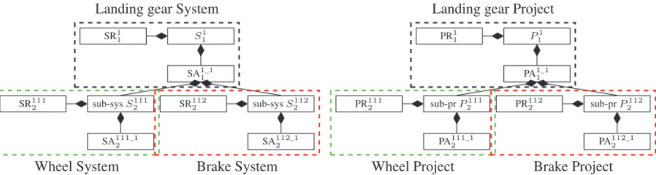
For example, let us consider a landing gear system S1
1composed of two sub-systems noted as S 111
2 for the
wheel and S112
2 for the brake, and the associated design
project P1
1 composed of two sub-projects noted as P 111 2
for the wheel project and P112
2 for the brake project.
The structure of the system S1
1 and of the project P 1 1
are illustrated in Fig.2.
We have to precise that the attribute of feasibility or that of verification for the whole system S or for the whole project P levels are not considered in our pro-posals. Indeed, these attributes aggregate the informa-tion on the feasibility and verificainforma-tion and are closely dependent on those of SR and SA for the system S, and on those of PR and PA tasks for the project P.
4.1. Feasibility Attribute Definition
In preliminary design, the feasibility characterizes the ability of a system, a product or a service to be developed technically and economically. During the feasibility evaluation phase, the design manager and the planning manager have to determine if they can reach a feasible solution with respect to their requirements, for instance performance and technical characteristics for a system or cost and duration for a project.
In order to qualify the feasibility of each system and each project, we propose adding a specific attribute to each entity, noted as Fa. This attribute has three states with different semantics:
– UD, for undetermined and default value, mean-ing that the design manager or the plannmean-ing man-ager has not yet determined if, with respect to the requirements, a solution seems achievable or not, – OK, for feasible, meaning that it seems possible to achieve a solution with respect to the requirements for the design or for the planning,
– KO, for unfeasible, meaning that it seems impos-sible to achieve a solution with respect to the re-quirements for the design or for the planning. In order to value the feasibility attribute xRi
n.F a, a
design manager or a planning manager firstly have to collect information on their own context and secondly to analyze it considering the degree of uncertainty and the risk of failure. It is important to note that the evalua-tion of the feasibility attribute relies on the skill and ex-pertise of the managers and their own subjective point of view on the whole situation. For the design side, when the needs and requirements have been gathered, the design manager has to analyze them, pre-design a solution and evaluate the risk of reaching an unfeasi-ble solution. For the project side, when the plan has been scheduled and the resources allocated, the plan-ning manager has to analyze the plan and evaluate the risk of reaching an unfeasible project. It is only after this phase that the managers can switch the value of their attribute to feasible, xRi
n.F a= OK or unfeasible,
SA1_1 1 S1 1 SR1 1 sub-sys S111 2 sub-sys S2112 SR111 2 SR1122 SA111_1 2 SA112_12 PA1_1 1 sub-pr P111 2 sub-pr P2112 P1 1 PR1 1 PR111 2 PR1122 PA111_1 2 PA112_12
Landing gear System Landing gear Project
Wheel System Brake System Wheel Project Brake Project
Fig. 2. Example of the Decomposition of a System into two Sub-systems and of a Project into two Sub-projects
For the design side, when it seems that a feasible solution is reachable for the requirements, the designer can start working on the solution itself SAi_jn . While (s)he has not described the functioning principles and possibly decomposed his/her system into sub-systems and identified their requirements, (s)he cannot deter-mine the feasibility of the solution. For the project side, when it seems that a feasible project is reachable for the plan and resource allocation, the planning manager can start working on the alternative development task PAi_jn . When (s)he has scheduled and possibly decomposed it into sub-projects, (s)he can switch the value of this attribute to feasible, P Ai_j
n .F a = OK or unfeasible,
P Ai_jn .F a= KO.
We can see that a relation of precedence exists be-tween the attributes of feasibility of xRi
nand of each
potential solution xAi_j
n . Therefore, we set up the rule
r1:
r1 : xRi
n.F a6= OK
⇒ ∀j ∈ [1, m], xAi_j
n .F a= UD (1)
In Fig.3and4, the relation described by the rule r1 (eq.1) between the feasibility attributes is synthe-sized. With regard to the association of these attributes, and without considering any rules or relations, there are3 ∗ 3 = 9 possible combinations for each pair of xRinand xAi_jn . Considering the rule r1 (eq.1), only5
combinations are permissible.
Let us consider now the case of a decomposed solu-tion into l sub-systems and l sub-projects. For the de-sign side, while the dede-signer has not identified each sub-system requirement and is not convinced of the feasi-bility of his/her decomposed solution SAi_jn .F a6= OK, the feasibility of each sub-system requirement can-not be determined: the feasibility attribute of each of the l sub-systems requirements is therefore
undeter-mined∀k ∈ [2, l], SRijkn+1.F a= UD. In the same way,
for the project side, as long as the planning manager has not identified each sub-project requirement (esti-mated resource workload, duration, budget, . . . ), has not scheduled it and is not convinced of the feasibil-ity of his/her decomposed alternative development task PAi_jn .F a 6= OK, the feasibility of each sub-project requirement definition task cannot be determined: the feasibility attribute of each of the l sub-project re-quirement definition tasks is therefore undetermined: ∀k ∈ [2, l], PRijkn+1.F a= UD.
We can see that a relation of precedence exists be-tween the attributes of feasibility of a decomposed solu-tion xAi_j
n and of the requirements of each sub-system
xRijkn+1. Therefore, we set up the rule dr1: dr1 : xAi_j
n .F a6= OK
⇒ ∀k ∈ [2, l], xRijkn+1.F a= UD (2)
In Fig.3and4, the relation described by the rule dr1 (eq.2) between the feasibility attributes of a decom-posed entity and two sub-entities is synthesized.
With regard to the association of these attributes with the decomposed entity xAi_11 and its two sub-entities
Xi11
2 and X2i12, and without considering any rules or
relations, there are3 ∗ 3 ∗ 3 = 27 possible combinations. Considering the rule dr1 (eq.2), only11 combinations are permissible.
4.2. Verification Attribute Definition
The definition of the verification comes from the ISO 9000:2000 standard [17]. After a complete design, the verification confirms through the provision of objective evidence that the specified requirements have been ful-filled. During the verification phase, the design
man-ager and the planning manman-ager have to justify that the solution matches their requirements to the letter.
In order to qualify the verification of each system and each project, we propose adding a specific attribute to each entity, noted as Ve. This attribute has three states with different semantics:
– UD, for undetermined and default value, mean-ing that the design manager or the plannmean-ing man-ager has not yet proven that the solution exactly matches the requirements to the letter or not, – OK, for verified, meaning that the solution fulfills
the requirements to the letter for the design or for the planning,
– KO, for unverified, meaning that the solution does not match at least one requirement for the design or for the planning.
The system requirements entity is composed of needs (expression of the stakeholders’requirements or the specifications stemming from the upper level if it exists) formalized by means of text or expressed as specifica-tions (both functional and technical) that are declined into technical requirements by the designers. As regards the definition of the verification, we do not associate a verification attribute with the system requirements. Indeed, in this case, it implies verifying that the re-quirements match the needs expressed by the client, the stakeholders or the upper level. We assume that this is the case and that a large majority of the specifications have already been formalized and tested against the upper-level needs.
For the project side, as regards verification, until a task ends, a planning manager cannot verify that it has run well: the verification attribute of all the tasks is therefore undetermined: PRin.V e= UD ∧ PAi_jn .V e=
UD. After a task has been carried out, the planning man-ager has to verify its validity compared to the project requirements: resource workload, real-time consump-tion, budget, . . . When (s)he has analyzed and if nec-essary, integrated all the information coming from the sub-projects, (s)he can verify the task and switch the value of its attribute to verified or unverified. A relation of precedence exists between the attributes of verifica-tion of these two tasks: we cannot verify an alternative development task before a requirement definition task. We set up the rule r2:
r2 : PRin.V e6= OK
⇒ ∀j ∈ [1, m], PAi_jn .V e= UD (3)
We can remark that a task PRin that has not been properly completed with respect to its requirements PRin.V e = KO does not compromise the rest of the complete project: the project can still continue but its requirements and objectives (estimated resource work-load, duration, budget, . . . ) have to be reassessed in order to achieve the design.
In Fig.4, the relation described by the rule r2 (eq.3) between the verification attributes is synthesized. With regard to the association of these attributes, and without considering any rules or relations, there are3 ∗ 3 = 9 possible combinations for each pair of PRi
nand PA i_j n .
Considering the rule r2 (eq.3), only4 combinations are permissible.
Let us consider now the case of a decomposed so-lution into l sub-systems and l sub-projects. For the design side, when the design of an alternative has been completed, the design manager has to verify its validity according to the requirements, SAi_jn .V e. As long as (s)he has not tested the functioning principles and po-tentially integrated all the sub-systems into the system, (s)he cannot determine the verification of the solution. The design manager has to wait for the verification of each sub-system and for its integration in order to deter-mine the verification of the decomposed solution. If one of the sub-systems is not verified∃SAijk_pn+1 .V e= KO,
de facto the complete solution cannot be either. But the fact that all the sub-systems have been verified∀k ∈ [2, l], ∀p ∈ [1, m], SAijk_pn+1 .V e = OK, is not enough
to determine if the decomposed solution matches the requirements to the letter or not because a problem can still occur during the integrations and tests.
In the same way, for a decomposed alternative de-velopment task, the project manager has to wait for the verification of each sub-project and for the in-tegration of its information, such as resource work-load, real time-consumption, or budget in order to de-termine the verification of the decomposed alterna-tive development task PAi_jn .V e. If one of the sub-projects is not verified∃PAijk_pn+1 .V e = KO, de facto the complete alternative development task cannot be either. But the fact that all the sub-projects are veri-fied∀k ∈ [2, l], ∀p ∈ [1, m], PAijk_pn+1 .V e= OK, is not
enough to determine if the decomposed alternative de-velopment task matches its requirements to the letter or not because a problem can still occur before its end.
We can see that a logical and precedence relation ex-ists between the attributes of verification of the l lower-level entities xAijk_pn+1 and of the decomposed entity
itself xAi_j
n . Therefore, the rule dr2 can be applied:
dr2 : ∀k ∈ [2, l], ∀p ∈ [1, m],
∃xAijk_pn+1 .V e= KO ⇒ xAi_j
n .V e= KO
or
∀xAijk_pn+1 .V e= OK ⇒ xAi_j
n .V e6= UD
(4) In Fig.3and4, the relation described by rule dr2 (eq.
4) between the verification attributes of a decomposed entity and of two lower-level entities is synthesized. With regard to the association of these attributes with the decomposed entity xAi_11 and its two sub-entities
X2i11and X2i12, and without considering any rules or
relations, there are3 ∗ 3 ∗ 3 = 27 possible combinations. Considering rule dr2 (eq.4), only11 combinations are permissible.
4.3. Feasibility and Verification Links
The possible states of this attribute V e depends on the previous value F a: an entity X cannot be verified if it has not been previously feasible. Therefore, we set up the rule r3:
r3 : X.F a 6= OK ⇒ X.V e = UD (5) Each of these attributes has three possible values (UD, OK or KO). With regard to the association of these attributes with the entities (X.F a, X.V e) and without considering any rules or relations, there are3 ∗ 3 = 9 possible combinations. Considering the rule r3 (eq.5), only5 combinations are permissible.
For these two attributes, the modification of require-ments at any stage in the design process by anyone (stakeholders, client, upper level) [12] implies a return to the initial state (X.F a= UD∧X.V e = UD) and the processes of feasibility and verification must be carried out again.
It is extremely important to point out that these two attributes can be switched to KO at any time in the processes. As soon as a problem with a negative impact on the global project is detected, these attributes have to be switched to KO, without waiting for the end of the current process. This scheme allows the managers to be immediately alerted that a problem has occurred. They will then have to find a common solution to solve it without threatening the overall success of the project.
4.4. Feasibility and Verification Attributes Synthesis
Seven synchronous attributes SRin.F a, SAi_jn .F a, SAi_jn .V e, PRi
n.F a, PAi_jn .F a, PRin.V eand PAi_jn .V e
ensure consistency in the design process by imposing precedence relations, through three precedence rules r1 (eq.1), r2 (eq.3) and r3 (eq.5), one top-down prece-dence rule dr1 (eq.2) and one bottom-up logical and precedence rule dr2 (eq.4), as synthesized in Fig.3
and4.
For the design side, without considering any rules or relations, there are3 ∗ 3 ∗ 3 = 27 possible combinations. Considering the precedence relations r1 and r3, and placing ourselves at a single decomposition level, there are7 possible combinations.
For the project side, without considering any rules or relations, there are3 ∗ 3 ∗ 3 ∗ 3 = 81 possible com-binations. Considering the precedence relations r1, r2 and r3, and placing ourselves at a single decomposition level, there are15 possible combinations.
Taking into account both sides and without consider-ing any couplconsider-ing rules, there are27 ∗ 81 = 2187 pos-sible combinations. If only the precedence relations r1 (eq.1), r2 (eq.3) and r3 (eq.5) are considered, there are7 ∗ 15 = 105 possible combinations.
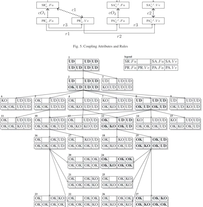
5. Synchronous Coupling Rules
The goal of synchronous coupling is to enforce syn-chronous milestones between the two processes. Two types of synchronous milestones have been identified: the first one relies on a relation of precedence between project planning and system design, rules cO1(eq.6)
and cO2 (eq. 7); the second one synchronizes them
without any dominance, rules c1, (eq.8) and c2 (eq.9), as shown in Fig.5.
Firstly, a relation of precedence exists between the project planning entities and the system design enti-ties. A designer cannot start working without a fea-sible project plan to which (s)he has been allocated and planned. This first coupling milestone is supported by the feasibility attributes and can be formalized as cO1for the requirement definition task and the system
requirements entity
SRi 1.F a SA i_1 1 .F a SRi11 2 .F a SAi11_12 .F a SAi11_12 .V e SRi12 2 .F a SAi12_12 .F a SAi12_12 .V e SAi_11 .V e r1 r3 r1 r1 r3 r3 dr1 dr1 dr2 dr2
Fig. 3. System Design Attributes and Rules
PAi_11 .F a
PRi11
2 .F a PRi112 .V e PAi11_12 .F a PAi11_12 .V e
PRi12
2 .F a PRi122 .V e PAi12_12 .F a PAi12_12 .V e
PAi_11 .V e PRi 1.Ve PRi 1.Fa r1 r3 r2 r1 r1 r2 r2 r3 r3 r3 r3 r3 dr1 dr1 dr2 dr2
Fig. 4. Project Planning Attributes and Rules
and cO2for the alternative development task and the
system alternative entity
cO2: PAi_jn .F a6= OK ⇒ SAi_jn .F a= UD (7)
Secondly, synchronization of the two processes is needed when one of them has reached a solution. Let us consider the pair (system requirements SRin, require-ment definition task PRin). Let us start with the system design side. When all the system requirements have been gathered and analyzed, the design manager has achieved his/her job and can deliver his/her conclusions on the risk of reaching an unfeasible solution. If the risk is weak SRin.F a = OK, the corresponding task PRi
n
has to end PRin.V e6= UD. On the other hand, where SRin.F a= KO, the requirements have to be modified in order to continue the design. In this case, the system design comes back to its initial state: SRin.F a= UD but the project side is not necessarily impacted by this modification. A renegotiation of the requirements with regard to the work already done can be supported by the AHP method [29]. Let us now look at the planning project side. When the task PRinis nearing its end, all the time has been consumed (PRin.V e 6= UD), so a decision has to be made on the feasibility of the system regarding the requirements. These two analyses allow us to deduce that a relation exists between the feasibil-ity of the system requirements SRin.F aand the
verifi-cation of the PRi
n.V etask. This relation is formalized
as:
c1 : SRin.F a6= UD ⇔ PRin.V e6= UD (8)
Let us consider the pair (system alternative SAi_jn , alternative development task PAi_jn ), starting with the system design side. When the whole solution has been completely designed, the design manager has achieved his/her job and can verify the consistency of the solution with regard to the requirements. If the solution matches the requirements SAi_jn .V e= OK, the corresponding task PAi_jn has to end PAi_jn .V e 6= UD. On the other hand, if SAi_jn .V e= KO, it will be necessary to modify the requirements in order to finish the design. In this case, the system design comes back to its initial state: SRi_jn .F a= UD∧SAi_j
n .F a= UD∧SAi_jn .V e= UD
and the project side is necessarily impacted by this modification: tasks PRinand PAi_jn have to be restarted and lengthened. The project keeps its time consumption but the complete process has to be carried out once more: PRi
n.F a= UD ∧ PRin.V e= UD ∧ PAi_jn .F a=
UD∧ PAi_jn .V e= UD. Let us now start with the
plan-ning project side. When task PAi_jn is nearing its end and all the time has been consumed (PAi_jn .V e6= UD), the system alternative has to be verified with regard to the requirements and then delivered. If a solution has not been designed, the complete project can start once
more. These two analyses allow us to deduce that a rela-tion exists between the verificarela-tion of the system alter-native SAi_jn .V eand of the verification of the PAi_jn .V e task. This relation is formalized as:
c2 : SAi_jn .V e6= UD ⇔ PAi_jn .V e6= UD (9) The goal of ensuring a better consistency between system design and project planning has now been reached through two specific attributes and nine rules. With regard to the seven entities (SRin.F a, SAi_jn .F a, SAi_jn .V e, PRni.F a, PRin.V e, PAi_jn .F aand PAi_jn .V e), there are2187 possible combinations (cf.
4.4). Considering now only the precedence rules r1 (eq.
1), r2 (eq.3) and r3 (eq.5), there are105 out of 2187 possible combinations (cf.4.4). Considering now all the precedence rules, and the coupling rules cO1(eq.
6), cO2 (eq.7), c1 (eq.8) and c2 (eq.9), the number
of possible combinations is reduced from105 down to 27, as shown in Fig.6. Only these27 combinations are allowed by the proposed coupling in order to monitor and synchronize these two processes.
In all the dead-end states (states 3, 6, 7, 9, 11, 13,14, 15, 17 and 18), a problem that can jeopardize the suc-cess of the project, had occurred. The design manager and the project manager have to find a common solu-tion that best suits system and project requirements at the same time to solve it. When the solution has been found, the process comes back to the initial state (state 1) in Fig.6, while keeping time, budget and resource consumption, for the project planning side, in order to consolidate these information at the project end.
6. Coupling Process Experimentation
This section highlights our proposals for coupling (structural and synchronous) with the simplified but re-alistic example of a landing gear system (cf. section4). This landing gear system is composed of one potential solution for level1 decomposed into two sub-systems (a wheel and a brake) and two sub-projects (a wheel project and a brake project) for level2, as shown in Fig.
2. In order to value the feasibility and the verification attributes, only two requirements are used: the weight for the system side and the duration for the project side.
Four typical coupling situations, belonging to a sce-nario, are described and show:
– The coupling process between entities on the same decomposition level (paragraphs [A], [B], [C] and [D]);
– The coupling process between entities between two successive levels (paragraphs [E] and [F]); – The fact that a project entity which has not been
properly completed does not compromise the de-sign project (paragraph [G]);
– That this is not the case for a system entity (para-graph [H]).
In the proposed scenarios, we follow the succession of states1, 2, 8, 12, 19 and finally 24 for the first scenario and27 for the second one in Fig.6.
[A] First of all, a program manager is appointed. (S)he starts creating a project entity and via the struc-tural coupling, six entities are automatically created P1
1, PR 1 1and PA
1_1
1 for the project side and S 1 1, SR
1 1
and SA1_11 for the system side, and matched{(S 1 1, P 1 1), (SR11,PR 1 1), (SA 1_1 1 ,PA 1_1
1 )}. All of these entities have
their attributes of feasibility and of verification to UD, state1 in Fig.6.
Then the program manager appoints the design man-ager and the planning manman-ager. Once this is done, (s)he gives them their orientations (objectives and require-ments) and defines their decision frames; for instance, the global budgets (for design and project), the time allotted to conduct the global project and the quantity of resources available. In our example, a 50-kilogram landing gear system has to be designed in 22 time units.
[B] The project side must be considered first. After collecting the information relevant to his/her context and exchanging views with all the people involved in his/her project (design and planning sides), the planning manager starts estimating the duration, allocating the resources and scheduling the requirement definition task PR1
1. In our example, (s)he allocates 2 time units
to task PR11and 16 units to task PA 1_1
1 . Two units are
needed to verify project P1
1, and in order to reduce the
risk of unfeasibility, a margin of 2 units is taken. When the plan has been scheduled and the resources allocated, it appears to the planning manager that this task PR1
1is viable: (s)he switches its feasibility attribute
to OK, PR1
1.F a= OK, state 2 in Fig.6. During state
2:
– Rule r3 (eq. 5) is applied and the requirement definition task can be now analyzed and verified. – Rule r1 (eq. 1) is applied and in our case, the
planning manager concentrates on the alternative development task PA1_11 . (S)he does exactly the
SRi n.F a SA i_j n .F a SA i_j n .V e r1 r3 PRi n.F a PR i n.V e PA i_j n .F a PA i_j n .V e r1 r3 r3 r2 cO1 cO2 c2 c1
Fig. 5. Coupling Attributes and Rules
UD UD UD UD UD UD UD 1 UD UD UD OK UD UD UD 2 UD UD UD KO UD UD UD 3 OK UD UD OK KO UD UD 4 OK UD UD OK OK UD UD 5 KO UD UD OK OK UD UD 6 KO UD UD OK KO UD UD 7 UD UD UD OK UD OK UD 8 UD UD UD OK UD KO UD 9 OK UD UD OK OK OK UD 10 OK UD UD OK OK KO UD 11 OK UD UD OK KO OK UD 12 OK UD UD OK KO KO UD 13 KO UD UD OK OK OK UD 14 KO UD UD OK KO OK UD 15 OK OK UD OK OK OK UD 16 OK KO UD OK OK OK UD 17 OK KO UD OK KO OK UD 18 OK OK UD OK KO OK UD 19 OK OK OK OK OK OK OK 20 OK OK KO OK OK OK KO 21 OK OK OK OK OK OK KO 22 OK OK KO OK OK OK OK 23 OK OK OK OK KO OK OK 24 OK OK KO OK KO OK KO 25 OK OK OK OK KO OK KO 26 OK OK KO OK KO OK OK 27 SR.F a SA.F a SA.V e PR.F a PR.V e PA.F a PA.V e legend
Fig. 6. Synchronous Coupling State Diagram
same job: duration estimation, resource allocation and schedulling.
– Rule cO1(eq.6) is applied, so the designers are
now allowed to start working and collecting the system needs and requirements.
[C] It appears to the planning manager that the al-ternative development task PA11_1is also viable: (s)he
switches its feasible attribute to OK, PA1_11 .F a= OK,
state8 in Fig.6. At this moment, this means that the whole project planning (requirement definition task PR11and alternative development task PA
1_1
1 ) are both
feasible with no conclusion on the feasibility of the system requirements SR11. During state8:
– Rule r3 (eq.5) is applied and only after the verifi-cation of the requirement definition task PR11(rule
– The coupling rule cO2(eq.7) is applied. But as
the design manager has not yet determined the fea-sibility of the system requirements, the designers cannot start working on a solution (rule r1, eq.1
has not yet been applied to the system side). [D] When the needs and requirements have been col-lected and analyzed (a 50-kilogram landing gear sys-tem designed in 22 time units), it seems to the design manager that a solution is reachable: (s)he switches the feasibility attribute of the system requirements entity to feasible SR11.F a= OK, state 12 in Fig.6.
Simultane-ously, the coupling rule c1 (eq.8) is applied and forces the corresponding task to end, PR11.V e6= UD. In our
scenario, as this task does not respect its requirements (for instance, the design team has spent too much time collecting and analyzing the system requirements, 3 units instead of 2), this attribute is switched to unveri-fied, PR1
1.V e= KO, by the planning manager, state 12
in Fig.6. But the fact that this task has consumed more than expected is not critical for the whole project. The planning manager has to negotiate new objectives and requirements with the program manager. This negoti-ation can involve the design manager in order to take into account design problems and constraints. If the negotiation is a success, the project continues, as in our scenario ; otherwise, it is stopped. In our example, the negotiation has led to splitting the margin as follows: 1 unit for task PR1
1and 1 unit for task PA 1_1
1 . During
state12:
– Rule r1 (eq.1) can be applied: as rule cO2(eq.7)
has already been applied, the design team can now start designing the system alternative SA1_11 .
– Rule r2 (eq.3) is applied and the alternative de-velopment task PA11_1can now be verified.
[E] In our first scenario, we consider that the system alternative SA1_11 is too complex to be designed in a
sim-ple way, so the design manager has to split it into several sub-systems. In our example, the landing gear system is decomposed into a wheel and a brake. In this case, firstly, the design manager decomposes his/her system alternative into x sub-systems (in our case, SA11_1 is
split into two sub-systems sub−sys S111
2 and sub−sys
S112
2 ). Secondly, via the structural coupling, the project
is decomposed in the same way into x sub-projects (in our case, PA11_1is split into two sub-projects sub− pr
P111
2 and sub−pr P
112
2 ) that the planning manager has
to analyze with regard to her/his project requirements (time and availability of resources). A complete cou-pling process has to be restarted for this new level and
for each pair of (sub-system SxRi
hl , sub-project PhlxRi: {(S111 2 , P 111 2 ), (S 112 2 , P 112 2 }).
[F] When the design team has described the function-ing principles of solution SA1_11 and given the
require-ments of each of the sub-systems SR1112 and SR 112 2 , the
feasibility of the solution can be determined. The de-sign manager specifies the weight of the sub-systems: 35 kg for the axle beam assembly (not considered in our example), 10 kg for the wheel and 5 kg for the brake. In our scenario, we consider that, regarding the require-ments and the decomposition into two sub-systems, a solution is reachable: the feasibility attribute of the al-ternative is switched to feasible SA1_11 .F a= OK, state
19 in Fig.6. Rule r3 (eq.5) is applied but the design manager has to wait for the verification of each of the sub-systems in order to verify the system alternative validity.
[G] When the design of each sub-system , sub− sys S111
2 and sub− sys S
112
2 , has been completed, the
de-sign manager has to integrate all the sub-systems, test the functioning of the system alternative SA1_11 , and
switch its verification attribute to OK or KO depend-ing on the results. In our first scenario, all sub-systems are verified SA111_11 .V e= OK and SA
112_1
1 .V e= OK
and their integration matches the requirements to the let-ter (9.9 kg for the wheel and 5 kg for the brake): the veri-fication attribute of the system alternative is switched by the design manager to verified SA1.V e= OK, state 24
in Fig.6. The coupling rule c2 (eq.9) is then applied and forces the corresponding task to end PA11_1.V e6= UD.
In our scenario, the task respects its requirements to the letter (17 units); its verification attribute is switched to verified PA1_11 .V e= OK, state 24 in Fig.6. At this
stage, all the feasibility and verification attributes on both sides have been determined, and the system design project is a success.
[H] In our second scenario, the verification attribute of the system alternative is switched to unverified SA1.V e = KO, state 27 in Fig.6. This switch can
come:
– From an integration problem of verified
sub-systems SA1111 _1.V e = OK and SA 112_1 1 .V e=
OK leading to a functioning problem. For instance, the wheel weighs more than required: its weight has not been verified properly by the sub-system design manager in charge of its design and it has been qualified as verified SA1111 _1.V e = OK. In
this case, it is the system design manager who has to switch this attribute to unverified SA1.V e =
– Or from a design problem, when it is impossi-ble for the sub-system design manager to reach a feasible solution regarding the requirements. For instance, it is not possible to design a wheel with such a low weight. The sub-system design manager has switched the verification attribute SA1111 _1.V eto KO. In such a case, the switch to
unverified is done automatically through rule dr21
(eq.4).
The coupling rule c2 (eq.9) is then applied and forces the corresponding task to end PA1_11 .V e 6= UD. The
task respects its requirements to the letter (less than 17 units), so its verification attribute is switched to verified PA1_11 .V e = OK, state 27 in Fig.6. At this stage, all
the feasibility and verification attributes on both sides have been determined. The project is interrupted be-cause there is a problem on the system design side. Two options are possible:
– Either the complete project ends;
– Or a discussion, involving the design manager, the project manager, the program manager and if nec-essary, all the stakeholders, has to be conducted in order to redefine the objectives, requirements and constraints. This discussion can lead, for instance, to enlarging the budget of the project, to fixing a new deadline, to allocating more resources, or to changing some of the requirements, etc. If the discussion comes to a compromise, the process of feasibility and verification must be carried out again: the process comes back to the initial state (state1 in Fig.6where all the attributes are val-uated to UD). But in this case, the time, budget and resource consumption has to be kept (and not reset) in order to consolidate the relevant infor-mation at the end of the project. For instance, in our example, a new weight distribution between sub-systems can be decided on.
7. Conclusion
The aim of this article is to propose a model and rules capable of supporting a coupling between the sys-tem design process and the project planning process. The context and the background of the study has been presented in section2and3. The multi-level design process and planning process have been described in accordance with academic standards and with standards used in companies. The natural and logical bijective relationships between system entities and project
en-tities (discussed in section3) is the base of the pro-posed structural coupling. The model that supports cou-pling groups together project entities (PRi
nand PAi_jn ),
systems entities (SRinand SAi_jn ) and coupling rules. In section4, we have proposed and defined specific attributes which are used to develop synchronous cou-pling: feasibility and verification attributes. These at-tributes allow states to be defined as entities during their life cycle and make it possible to control their consistency throughout the design of the whole system. Three precedence rules r1 (eq.1), r2 (eq.3) and r3 (eq.
5) on a single level of decomposition, as well as two hierarchic rules dr1 (eq.2) and dr2 (eq.4) have been set up between system attributes or project attributes. In section5, synchronous coupling is described by iden-tifying different states and transitions between these states for entities, and by defining some rules which guarantee the consistency of the transitions. In other words, the proposed coupling synchronizes the project planning process with the system design process while preserving consistency between the changing of states. It authorizes certain attribute changes and forbids oth-ers, leading to better planned and controlled design tasks. Firstly, two precedence coupling rules cO1 (eq.
6) and cO2 (eq.7) order the two processes: the feasi-bility of project entities must be qualified before those of the system. Secondly, two synchronized coupling rules c1 (eq.8) and c2 (eq.9) synchronize them: none of the processes prevails on the other but a change in one or the other environments has a strong impact on the other (for instance, the delivery of a system implies the end of the associated task and vice-versa). Finally, in section6, a coupling scenario is described in order to illustrate the proposal.
The proposed synchronous coupling is quite simple but very powerful. The formalization of the behavioral interaction, which no previous scientific paper has made explicit, is unquestionably original. The nine identified rules have been set up thanks to the fifteen company in-terviews. In some specific situations, some of them can be needless. Of course, the less the coupling rules are applied, the more the resulting synchronous coupling state diagram has states compared to the one presented in Fig.6.
These rules have been integrated in the ATLAS IT platform which has been developed in order to test and validate our proposals. Some tutorials and the link to the prototype can be found on the
follow-ing webpagehttp://perso.mines-albi.fr/
~vareille/, heading "Projects and industrial part-ners" and project "ATLAS".
It must be clear that according to the industrial devel-opment context, other rules could be added. This opens interesting issues leading to a kind of customization of the coupling process. Structural and synchronous couplings can be added, without any difficulty, to PLM software. In this case, engineers and managers would be forced to discuss together and to find a compromise acceptable to both sides, before a project failure occurs. Structural and synchronous couplings could help them to identify problems as early as possible and thus make better decisions by considering the overall situation.
Perspectives of this work concern the integration of local decoupling mechanisms between both domains when required at lower levels of decomposition. In this case, the coupling could be carried out manually (the program manager explicitly constructs the links between entities) and all the identified couplings con-tinue to work. Alternatively, no coupling is performed and is thus no longer supported by the integrated model. Clearly, this method of operation needs to be checked and reserved for specific situations where designers of low levels want to decompose a very simple system to develop it without a framework given by the planning environment.
References
[1] J. Abeille, T. Coudert, E. Vareilles, L. Geneste, M. Aldanondo, T. Roux, Formalization of an integrated system/project design
framework : first models and processes, SPRINGER , pp.207-217, ISBN 978-3-642-15653-3, 1st International Conference on Complex Systems Design and Management CSDM2010, Paris, FRANCE, 2010.
[2] L. Albano, N. Suh, Axiomatic approach to structural design, Research in Engineering Design, Vol. 4, pp. 171-183, 1992. [3] M. Aldanondo, E. Vareilles, M. Djefel, Towards an association
of product configuration with production planning, International Journal of Mass Customisation 2010 Vol. 3, No. 4 pp. 316 -332, 2010.
[4] L. T. M. Blessing, Comparison of Design Models Proposed in
Prescriptive Literature, Proceedings of the COST A3 / COST A4 International Research Workshop on the role of design in the shaping of technology, Lyon, 1996.
[5] F. Demoly, X.-T. Yan, B. Eynard, S. Gomes and D. Kiritsis,
Integrated product relationships management: a model to enable concurrent product design and assembly sequence planning, In Journal of Engineering Design, Vol. 23, pp. 544-561, 2012. [6] G. E. Dieter, Engineering design - A materials and processing
approach, Mc Graw-Hill International Editions, 2000. [7] I. Dörfler and O. Baumann, Changing Organizational Routines in
Response to a Drastic Failure: The Case of Airbus A380 Program, Available at SSRN 2123297, 2012.
[8] EIA Standard, Processes for Engineering a System, Electronic Industries Alliance, 1999.
[9] S. D. Eppinger, D. E. Whitney, R. P. Smith D. A. Gebala,
Orga-nizing the tasks in complex design projects., MIT Workshop on CAOPD, Springer-Verlag New York, Inc. 1991.
[10] J. S. Gero, Design prototypes: a knowledge representation
schema for design, Artificial Intelligence magazine. Vol. 11 No. 4, 1990.
[11] S. Gomes and J-C. Sagot, A concurrent engineering experience
based on a cooperative and object oriented design methodology, Best papers book, 3rd International Conference on Integrated Design and Manufacturing Engineering, Kluwer Academics Pub-lisher, pp. 11-18, 2002.
[12] E. Gómez de Silva Garza, M. L. Maher, Design by interactive
exploration using memory-based techniques, Knowledge-Based System Journal, Vol. 9, No. 3, pp. 151-161,http://dx.doi. org/10.1016/0950-7051(95)01016-5, 1996. [13] A. Goncalves-Coelho, Axiomatic Design and the Concurrent
Engineering Paradigm, Proceedings of COSME, Brasov, Roma-nia, 2004.
[14] H. Hans, W. Herroelenb, R. Leusb, G. Wullink, A hierarchical
approach to multi-project planning under uncertainty, The Inter-national Journal of Management Science, Vol. 35, pp. 563 - 577, 2005.
[15] W. Herroelen, B. De Reyck, E. Demeulemeester,
Resource-constrained project scheduling: a survey of recent developments, Computers and Operations Research, Vol. 25, No. 4, pp. 279-302, 1998.
[16] J. Huysentruyt, D. Chen, Contribution to the development of
a general theory of design, Proceedings of the 8th International Conference of Modeling and Simulation - MOSIM’10 - May 10-12, 2010 - Hammamet - Tunisia, 2010.
[17] ISO 9000:2000, Quality management systems -
Funda-mentals and vocabulary, International Organisation of Stan-dardization, http://www.iso.org/iso/catalogue_ detail?csnumber=29280, 2005.
[18] A. Karnie and Y. Reich, Managing the Synamic of New Product
Development Processes. A new Product Lifecycle Management Paradigm, Springer, P. 13, 2012.
[19] T. Kis, Project scheduling: a review of recent books, Operations Research Letters, Vol. 33, Issue 1, pp. 105-110, 2005. [20] M. Lamers, Do you manage a project, or what? A reply to
"Do you manage work, deliverables or resources", International Journal of Project Management, Vol. 20, Issue 4, pp. 325-329, 2002.
[21] P. Lawrence and J. Scanlan, Planning in the Dark: Why Major
Engineering Projects Fail to Achieve Key Goals, Journal of Tech-nology Assessment and Strategic Management, Vol. 19, Issue 4, pp. 509-525, 2012.
[22] U. Lindemann, A vision to overcome "chaotic" design for X
pro-cesses in early phases, Int. Proc. of Conference on Engineering Design (ICED), Paris, France, 2007.
[23] J. N. Martin, Evolution of EIA-632 from an interim standard
to a full standard, Proceedings of INCOSE 1998 Symposium, 1998.
[24] G. Pahl, W. Beitz, Engineering Design: a Systematic Approach, Springer-Verlag, 1996.
[25] PMBOK Guiden A Guide to the Project Management Body of
Knowledge, Fifth Edition, Project Management Institute, 2013. [26] G. Pol, C. Merlo, J. Legardeur, G. Jared, Analysing
collabo-rative practices in design to support project managers, Interna-tional Journal of Computer Integrated Manufacturing, Taylor & Francis, Vol. 20, No. 7, pp. 654-668, November 2007.
[27] H. Li, Y. Fan, C. Dunne, P. Pedrazzoli, Integration of business
processes in Web-based collaborative product development, Inter-national Journal of Computer Integrated Manufacturing, Taylor & Francis, Vol. 18, No. 6, pp. 452-462, September 2005. [28] R. Lu, W. Peng, C. Wang, Integration of Product Design
Pro-cess and Task Management for Product Data Management Sys-tems, in proceedings of IFIP International Federation for Infor-mation Processing, Volume 254, Research and Practical Issues of Enterprise Information Systems II Volume 1, eds. L. Xu, Tjoa A., Chaudhry S. (Boston: Springer), pp. 207-218, 2007. [29] T. L. Saati, Engineering Design: a Systematic Approach, RWS
Publications, 3rd Revised edition, 2012.
[30] H. A. Simon, The science of the artificial, MIT Press, 1969. [31] A. Sharon, V. Perelman, D. Dori, A Project-Product
Lifecy-cle Management Approach for Improved Systems Engineering Practices, Proc. Eighteenth Annual International Symposium of the International Council on Systems Engineering (INCOSE), Utrecht, the Netherlands, 2008.
[32] A. Sharon, O. de Weck, D. Dori, Is there a Complete Project
Plan? A Model-Based Project Planning Approach, Proceedings of the Nineteenth Annual International Symposium of the Inter-national Council on Systems Engineering (INCOSE), Singapore, 2009.
[33] B. Shore, Systematic biases and culture in project failures, Project Management Journal, Vol. 39, Issue 4, pp. 5-16, 2008. [34] D. Stewart, D. Tate, Integration of Axiomatic design and project
planning, Proc. of first Int Conference on Axiomatic Design, Cambridge USA, 2000.
[35] N. Suh, The principles of Design. Oxford series on Advance
Manufacturing, Oxford University Press, New York, 1990.
[36] N. Suh, Axiomatic Design: Advances and Applications, Oxford Series, 2001.
[37] M. X. Tang, A knowledge-based architecture for Intelligent
Design Support, International Journal of Knowledge Engineering Review, vol. 12 (4), pp.387-460, 1997.
[38] D. G. Ullman, The mechanical design process, third edition, McGraw-Hill, Higher Education, New York, 2003.
[39] É. Vareilles, M. Aldanondo, M. Djefel, P. Gaborit, Coupling
interactively Product and Project Configuration: a Proposal us-ing Constraints Programmus-ing, International Mass Customization Meeting (IMCM) and International Conference on Economic, Technical and Organizational Aspects of Product Configuration Systems (PETO), 2008.
[40] É. Vareilles, T. Coudert, M. Aldanondo, L. Geneste, J. Abeille,
Coupling system design and project planning: discussion on a bijective link between system and project structures, forthteenth edition of IFAC’s triennal symposium on Information Control Problems in Manufacturing (INCOM), 2012.
[41] J. X. Wang, M. X. Tang, B. Gabrys, An Agent-Based System
Supporting Collaborative Product Design, R.J. Howlett, L.C. Jain
(Eds.): KES 2006, Part II, LNAI 4252, pp. 670 - 677, Springer-Verlag Berlin Heidelberg, 2006.
[42] H. Yoshikawa, Design philosophy: the state of the art, CIRP annals manufacturing technology, 38(2) : pages 579-586, 1989. [43] X. Zhang, Y. Li, S. Zhang, C. M. Schlick, Modelling and
simu-lation of the task scheduling behavior in collaborative product development process, Integrated Computer-Aided Engineering, vol. 20 (1), pp. 31-44, 2013.