Publisher’s version / Version de l'éditeur:
Vous avez des questions? Nous pouvons vous aider. Pour communiquer directement avec un auteur, consultez la
première page de la revue dans laquelle son article a été publié afin de trouver ses coordonnées. Si vous n’arrivez pas à les repérer, communiquez avec nous à [email protected].
Questions? Contact the NRC Publications Archive team at
[email protected]. If you wish to email the authors directly, please see the first page of the publication for their contact information.
https://publications-cnrc.canada.ca/fra/droits
L’accès à ce site Web et l’utilisation de son contenu sont assujettis aux conditions présentées dans le site LISEZ CES CONDITIONS ATTENTIVEMENT AVANT D’UTILISER CE SITE WEB.
Research Report (National Research Council of Canada. Institute for Research in Construction), 2008-03-01
READ THESE TERMS AND CONDITIONS CAREFULLY BEFORE USING THIS WEBSITE. https://nrc-publications.canada.ca/eng/copyright
NRC Publications Archive Record / Notice des Archives des publications du CNRC :
https://nrc-publications.canada.ca/eng/view/object/?id=9ce32524-7e7b-4fba-b095-623c0efb9b57 https://publications-cnrc.canada.ca/fra/voir/objet/?id=9ce32524-7e7b-4fba-b095-623c0efb9b57
NRC Publications Archive
Archives des publications du CNRC
For the publisher’s version, please access the DOI link below./ Pour consulter la version de l’éditeur, utilisez le lien DOI ci-dessous.
https://doi.org/10.4224/20377669
Access and use of this website and the material on it are subject to the Terms and Conditions set forth at
Advanced Portable Visualization System
http://irc.nrc-cnrc.gc.ca
A d v a n c e d P o r t a b l e V i s u a l i z a t i o n S y s t e m
R R - 2 5 5
A h a m e d , S . ; M u r r a y , N . ; K r u i t h o f , S . ; W i t h e r s ,
E .
M a r c h 2 0 0 8
The material in this document is covered by the provisions of the Copyright Act, by Canadian laws, policies, regulations and international agreements. Such provisions serve to identify the information source and, in specific instances, to prohibit reproduction of materials without written permission. For more information visit http://laws.justice.gc.ca/en/showtdm/cs/C-42
Les renseignements dans ce document sont protégés par la Loi sur le droit d'auteur, par les lois, les politiques et les règlements du Canada et des accords internationaux. Ces dispositions permettent d'identifier la source de l'information et, dans certains cas, d'interdire la copie de documents sans permission écrite. Pour obtenir de plus amples renseignements : http://lois.justice.gc.ca/fr/showtdm/cs/C-42
TABLE OF CONTENTS
1. Executive Summary ... 4
2. Background ... 5
3. Scope... 5
4. Definitions of the Nomenclature... 6
5. Building the System... 6
5.1 Hardware... 7
5.2 Software... 7
5.3 Methodologies... 8
5.4 Building Blocks ... 10
6. Features of the Developed System ... 13
7. Limitations of the Developed System ... 14
TABLE OF FIGURES
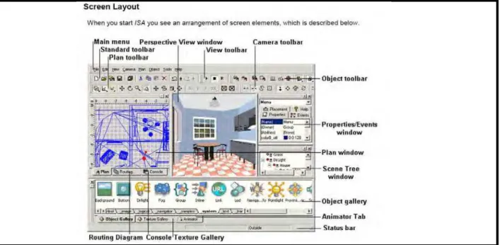
Figure 1: Snapshots of theTexturing Process for the Floor Object 11 Figure 2: Snapshot of the Screen Layout ... 11
Figure 3: Snapshot of the Final Application ... 12
Figure 4: Snapshot Showing the Door Object Opening during the Walkthrough 13
1. Executive
Summary
Digital modeling and advanced visualization are in use by many disciplines worldwide to improve decision-making by reducing risk and minimizing cost. The wider adoption of these technologies is hindered by the cost of the hardware, the lack of portability, the availability of dedicated software applications and the difficulty inherent in using the available technology by practitioners.
Current advances in consumer-level computing and visualization techniques enable users to interact with large digital models at low cost. This creates the opportunity to bring large data sets and interactive technologies directly to the practitioners’ desktop. As the technologies in computing, display, interaction and software are maturing, a broader range of tools and technologies are becoming available commercially at a lower cost. This gives the user an opportunity to pick and choose technologies depending on the budget and the desired functionalities.
This document describes the elements of a portable advanced visualization system, methodologies for building an application and a demonstration of a building model, as an example. The system can serve as a plug and play platform for rapid application
development. Compared to proprietary hardware of the past, which relied heavily on embedded platform technologies, the proposed system uses desktop personal computer hardware technologies with the Windows® operating system.
This system can serve as a rapid prototyping tool in the visualization context to the AEC industry. Access to the visualization of large datasets in 3D immersive environments gives the user a sense of presence. Having such tools will allow construction practitioners to better visualize product and process information and will reduce the need to invest in building physical models for decision making.
This work explores the possibilities of using inexpensive, commercially available devices to build an advanced visualization system to assist construction practitioners. The developed system is believed to serve the following AEC stakeholders.
Group Application Domain
Architects Plan, develop and visualize concept models. Visualize large datasets of exterior/interior of buildings, infrastructure, landscape, lighting and product supplies.
Civil Engineers Plan, develop and visualize project concepts. Visualize concept models, detail models of exterior/interior of building, infrastructure, structural models andbuilding components.
Contractors Visualize detail models of exterior/interior sub-components of buildings and infrastructure, structural models, lighting, product supplies, assembly of their components with other components in the building.
Group Application Domain
Simulation of assembly processes of pre-fabricated building components.
Product Manufactures Demonstrate products to potential customers, process of integrating products using virtual assembly.
Clients and Stakeholders
Visualize concept models to assist in decision making. Facility Managers Assist in maintenance of buildings and infrastructure.
2. Background
Many standalone tools, technologies and equipment exist to cater to the needs of
visualization and interaction with large datasets. Generally, the integrated systems available in the market are expensive and allow limited equipment inter-operability.
Data and information are crucial to construction practitioners at various phases in the
lifecycle of the property. Often different people require different sets of data. This is typically accomplished by sharing 2D annotated drawings through a variety of means ranging from fax to net-meetings and this creates opportunities for misinterpretation. Resolving
misinterpretations results in time delays and increased cost. In addition, embedding
geometric and non-geometric information inside the models, to increase realism, uses large amounts of memory requiring bulky hardware systems. With the advancement of 3D visualization, data representation and inter-operability, it is now possible to use desktop systems to address these issues.
In order to bridge the gap between the physical and virtual world, systems which look, sound and behave realistically are required. In other words, the virtual world needs to be able to respond similarly to the user interacting with physical models. Realizing such a system is a time consuming, involved process. As an initial step, development of an advanced portable visualization system to display building models in a 3D stereoscopic mode is proposed.
3. Scope
The project uses 3D geometric models from Autodesk® Revit® BIM software. The models are enhanced to add visual realism; such as, lighting and image mapping. Objects are grouped to enable user selections for interactivity using 3ds Max®, ISB®, ISA®, Cortona® and VRML Pad.
Commercially available stereo-capable display equipment from Samsung®, a desktop computer with a mouse and keyboard are used in this project for computing and display interaction. Special shutter-type eyewear from StereoGraphics is used to enable 3D visualization.
4. Definitions of the Nomenclature
AEC: Architecture/Engineering/Construction
BIM: Building Information Modeling
Datum: A point, axis or plane derived from true specified feature. An origin from which the location of form features of object is established
DVI: Digital Video Interface
HDMI: High-definition Media Interface
IFC: Industry Foundation Class, an industry standard data structure for
exchanging information about construction related objects and activities
ISA: Internet Scene Assembler
ISB: Internet Scene Builder
LOD: Level of Details
VRML: Virtual Reality Modeling Language, a standard format for
representing three dimensional vector graphics for developing virtual reality applications
5. Building the System
A stable, user-friendly, powerful system is required to bridge the gap between construction practitioners and advanced technologies to facilitate better decision-making. The developed applications should be concise to their specific needs and provide adequate ease of use. Interactivity is a crucial component in a
Human-Computer Interface (HCI), which serves as a bridge between the user, computer and environment. HCI involves interactions with several devices simultaneously. Well-developed sequencing of these interactions leads to a user-friendly system. Typically, the following interface types help build an interactive system:
• Text-based • Menu-based • Form-based • Graphics-based
There are three important feature characteristics to be considered when building an interactive system; namely, appearance, behavior and navigation. The appearance features describe the layout, graphics and color attributes. The behavior features
incorporate the control and default values. The navigation features provide the guides, maps, exit points, browse and scroll capabilities within the system.
The advanced visualization system is a 3D stereo capable display system wherein the user will have depth perception. This system uses stereoscopic visualization display techniques. Stereoscopic visualization involves the projection of two images
simultaneously, one image for the left eye and one for the right eye. The human brain combines these two images to perceive depth. Thus, a scene with two separate images, fully focused for each eye, is crucial for advanced visualization.
Presently, there are two main stereoscopic image projection techniques, namely, passive and active. Passive systems consist of one or more projectors and use light polarization filters to differentiate the images. The eyewear for passive systems has polarized filters for each eye. Active stereo systems consist of a single projector or display device and special eyewear. The eyewear consists of two liquid crystal display shutters working in sync with the projecting device. When the projector projects a left eye image, the right eye shutter is shut-off and the process is reversed and repeated. Building the integrated system for portable advanced visualization requires specific display hardware. Developing unique methodologies for enhancing the models and adding interactivity required the use of various software packages. The following sub-sections describe these specific tasks.
5 . 1 H a r d w a r e
The hardware consists of a 61” widescreen LED 3D DLP television from Samsung® capable of displaying 1920 x 1080p HD quality images. The contrast ratio is 10,000:1 which renders images in detail making them suitable for AEC visualization applications. For the Samsung® 3D TV to display in stereoscopic mode, a DVI to HDMI cable is required to connect the PC video output to the 3D HDMI port on the display TV. A StereoGraphics emitter connects to the display TV to synchronize the images with the eyewear. A standard desktop PC equipped with an appropriate graphics card that supports stereo visualization is used. Appendix A describes the detailed configurations and the initial setup of the display and the computing hardware.
5 . 2 S o f t w a r e
The application has been developed by using capabilities from a number of commercial software products, listed in the following table.
Software Company Features Used in the project for
1 AutoCAD® Revit®
Autodesk® Inc Revit Architecture software is a complete, discipline-specific building design and documentation system supporting all phases of design and construction.
Source of building design models and their components. 2 Autodesk®
3ds Max®
Autodesk® Inc Create complex realistic design visualization environment with 3D and visual effects. Provide platform for modeling, animation and rendering.
Enhancing objects and scenes, building object tree structure.
3 PolyTrans® Okino Computer Graphics
Highly refined conversion, translation and enhancing package to suit a wide variety of input data.
Translation of the geometric design models and components; control details etc. 4 Internet
Space Builder®
Parallel Graphics
Authoring tool for creating, enhancing and developing visual applications. Provides an environment for texture editing, mapping and scene creation.
Creating objects and building scenes. 5 Internet Scene Assembler® Parallel Graphics
Authoring tool to facilitate the creation of interactive and dynamic applications.
Creating intelligent, dynamic objects. Assembly of scene with interactivity. 6 VrmlPad® Parallel Graphics
Editor for manipulating VRML format data Editing VRML data.
7 Cortona3D Viewer®
Parallel Graphics
VRML optimized viewer to generate 3D quality images and a VRML plug-in for high-end visualization.
Viewer and plug-in for display.
8 TriDef® Dynamic
Digital Depth
Allows third-party applications to display in real-depth stereoscopic models
Enables 3D visualization for Cortona® VRML client.
5 . 3 M e t h o d o l o g i e s
5.3.1 Geometric Models - CAD systems are the main source for 3D geometric design
models. Advanced visualization uses a lighter representation of 3D models as compared to proprietary formats in CAD systems. Proprietary CAD formats do not provide the ability for real-time interactivity because of their native representations. Translators convert these native representations into formats that are acceptable in down-stream applications. Modifications to the translated models enable the use of a wide range of display and interactive devices.
Models in AEC consist of a variety of structural, mechanical, electrical, plumbing and civil objects. Complex objects combine several basic geometrical shapes. Many objects that are combined; such as, doors, windows, floors and walls, form a complex structure. The combination of several structures creates a scene. Adding properties and attributes to each of these objects will enrich the appearance and behavior of the model.
BIM models from Autodesk Revit® are one source of input geometry for the developed
enhancement, conversion of these BIM models from the Revit® environment to the
AutoCAD® design system format is crucial. The 3ds Max® application enhances the
geometry to make the models more realistic. The advanced visualization system needs optimized and enhanced data models for faster response and realistic visualization. Specifically, this project uses a VRML model format to convert design data from CAD systems to enhancing and visualization systems. Appendix B lists some of the other tools and technologies available.
VRML is an open standard file format designed for representing three dimensional vector graphics. VRML represents and defines object grouping, scene development and user interactions on any standard computing platform. Thus, it is used extensively in creating virtual environments. The VRML format, in conjunction with the Cortona®
VRML browser plug-in, was chosen for developing the advanced portable visualization system because of the following specific characteristics:
Platform independence: VRML code is interoperable between UNIX®, Macintosh® and
Windows® platform systems.
Extensibility: Objects that are not included in standard VRML can provide a description that VRML can interpret as required.
Efficiency: VRML has the ability to represent and store data as both human readable ASCII text files and high performance binary files. Selective refinement: VRML has the ability to add additional details only to the portion
of the scene that requires it.
3-D hyperlinks: Activate dynamic links as you move the mouse pointer over certain VRML objects.
Texture mapping: Images applied to the surfaces of 3D objects to give them realistic appearance.
Structure: Tree-type hierarchical structures of objects for realistic scene manipulation.
5.3.2 Enhancing the Models - The 3D geometric digital models used for this work are
input from Autodesk Revit® BIM environment. These 3D geometric models are translated
and enhanced to suit the visualization environment. The process of enhancing the models consists of applying lighting and textures to the scene and its objects. Many image variables, such as color balance and brightness, play a significant role in the lighting and texturing of the model to increase its visual realism. Textures are applied to objects in 3D Studio MAX, then lighting and controls for interacting with the scene are added in the ISA environment to achieve the desired enhancements.
5.3.3 Translation of the Models – The translation involves a multi step process. In the
first step, models received from the CAD system or BIM environment are transferred to the enriching environment. Here they can be enhanced with lighting and textures. The
second step involves porting these enhanced models to the application development platform wherein the required interactivity is built. The final step involves porting the built application to a presentation platform where the user can visualize and interact with the scene.
To ensure a seamless transfer from design environments to enhancing environments, such as 3ds Max®, models from Autodesk’s Revit® system must be translated using
the Autodesk® proprietary DWG® format. The translation process from 3ds Max® into
the VRML format involves the plug-in translator “PolyTrans®” from Okino Inc. It is
crucial to provide high quality data containing units, scale factor, origin location and coordinate transformations that is properly formatted for downstream applications. Optimization of the VRML data files provides reduced polygon count, LOD control and efficient object tree structure for high rendering performance, intuitive interactivity and a realistic look. These VRML models are migrated to the desired development platform. Authoring tools assist in building interactive applications.
5.3.4 Authoring Tools - VRML is gaining wide acceptance in visualization
applications. This wider acceptance is leading to the availability of a greater number of authoring tools. These tools assist in the creation of simple animations all the way up to complex immersive virtual world applications. The selection of an authoring tool
depends on the application to be developed. A list of VRML authoring tools is listed in Appendix B.
In this project, a suite of authoring tools from ParallelGraphics is used to build the application with the desired specifications and functionality. Functions include object editing such as rotation, scale, deformation and mirroring. Behavior and control mechanisms are embedded into objects which are grouped logically to create an interactive scene. This feature enables the user to select objects in a scene and interact with the models.
The ISA® tool from ParallelGraphics facilitates the creation of interactive and dynamic
3D scenes that involve logic and behavior. 3D scenes, created with ISA, produce
models suited for both advanced visualization and web publishing. The ISA environment consists of a library of standard modules to load, control and manipulate geometric objects. Each ISA block, defined in the gallery, has properties and events associated with it. There are many property and event types. Position, rotation, scale and translation are examples of property types. Highlighting, selection and action triggers are examples of event types.
5 . 4 B u i l d i n g B l o c k s
Several work tasks are required to build an advanced visualization system. The first task is to analyze the models at the source, cleanup unwanted geometry and control the LOD. Next, translate the models from the source to the enriching environment to add visual features. A proper translation format ensures a seamless translation with no loss of data. Later, the properties and events are added to the enhanced geometrical models and then a tree structure representation is built, using these enhanced geometric
for visualization and interaction by the user.
5.4.1 Model Realism – The visual realism of the scene is greatly enhanced by the
addition of texturemaps. Texture maps are digital images that have been manipulated to conform to the needs of the rendering visualization. Manipulations include the removal of perspective from an image, the trimming of unneeded image data and the balancing of the colours to prevent images from conflicting. Adobe Photoshop®
software is used to perform these image manipulations. Each object in the scene is texture mapped with a corresponding image using 3ds Max®. The result is a scene that
resembles a real life environment. Figure 1 shows a snapshot of the texturing process for the floor object.
Figure 1: Snapshots of theTexturing Process for the Floor Object
5.4.2 Interactivity – This section deals with the HCI developed using the authoring
tools. The following example illustrates the methodology used to develop a menu interface. The menu interface allows the user to select objects, scenes and viewpoints allowing interaction with the graphic model. Figure 2 shows a snapshot of the screen layout in the ISA development environment. Note: ISA terminology is used in the procedures below.
5.4.2.1 Procedure to develop menu interfaces in ISA
1. Create/import the scene into the Perspective View Window.
2. Set the default starting viewpoint location (vantage point). Use the ISA
“Viewpoint” object from the system group of the object library to define vantage points.
3. Name these viewpoints; they appear in the Scene Tree Window.
4. Create a "Selector" object using the drag and drop "SelectorBool" object from the "Logical" group of the object gallery.
5. Create a group using the drag and drop "Group" object from the "System" group of the object gallery.
6. Drag and drop the “CheckBox” object from the "Text" group of the object gallery to create a check box.
7. Create a menu list using the drag and drop "Menu" object from the "Control" group of the object gallery.
8. Nest "CheckBox" and "Menu" inside the "Group" object.
9. To engage with the developed interactions, click on the Play button. The developed interface with options will appear on the screen. Select an option to activate.
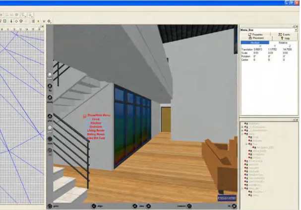
Detailed procedures including the properties and events of each object mentioned above, with relevant snapshots for developing interactions with the environment, are described in Appendix C. The snapshot of the final application is shown in Figure 3.
5.4.2.2 Procedure to develop walkthrough scenarios involving animation In order to accomplish a walkthrough scenario, which has animation capabilities, a number of requirements have to be fulfilled; such as, identify animation objects in a scene, their initial and final positions and orientations, the step size, the process of triggering the animation and associated events and the walkthrough path. In this project, examples of the animation of doors in the building are developed. Approaching the door triggers animations to simulate the opening of the door during the walkthroughs. The doors will close as you leave the vicinity of the door. “Proximity Sensor” objects control events. The following three major steps are involved in creating animated walkthrough scenarios:
1. Building a pre-defined path for the walkthrough. 2. Animating pre-defined objects.
3. Adding behavior properties to the objects.
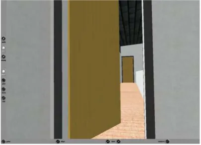
Figure 4 shows a snapshot of the walkthrough scenario with animation of door object in the scene. Appendix D describes the procedure to animate, add behavior and build a walkthrough scenario.
Figure 4: Snapshot Showing the Door Object Opening during the Walkthrough
6. Features of the Developed System
Currently, the portable system supports the following in 3D stereoscopic visualization: a) Virtual walkthrough – the user has the option of navigating in walk and fly modes,
in either a controlled or self-directed manner.
b) Scene and object control – the user has the option to select and change
predefined scenes and viewpoints. Objects can be selected to manipulate their geometric and visual properties via a standard mouse.
c) Functional simulation – the user can visualize the functional performance of selected objects via animation.
d) Models can be exchanged over the Internet for users to visualize with any standard Internet Browser in non-stereo mode.
7. Limitations of the Developed System
The current system is not a modeling tool.
8. Future Work
• Develop an environment for the review of concepts, layouts, proposals, with mark-up and web-collaborative functionalities.
• Extend the plug-and-play features.
• Integrate with databases to access information in real-time such as product manufacturers’ data.
APPENDIX A:
SETUP PROCEDURE TO LAUNCH THE APPLICATION:
1. Make sure that the appropriate 3D display client (Cortona® Client) and drivers (TriDef 3D Visualizer® driver for Cortona® Client) are installed on the computing device.
2. Connect the DVI video output on the PC to the 3D HDMI input on the display television using a DVI to HDMI cable.
3. Set the display television to 3D mode using the remote.
4. Connect the StereoGraphics emitter to the 3D Sync Out port on the display television. The emitter must face the audience.
5. Start the visualization by double clicking on the “House.wrl” icon on the desktop. 6. Click the right mouse button; select Preferences from the drop down list.
7. Click the Render tab and select the Open GL option. Close the window.
8. A menu screen appears. Follow the menu to perform the various functions. The last menu item will execute an automated flythrough of the scene.
APPENDIX B:
LISTS SOME OF THE COMMERCIALLY AVAILABLE VRML BROWSERS/VIEWERS/PLUG-INS:
Name Company /URL Feature
Cosmo Silicon Graphics Cosmo Player is a free,
high-performance, cross-platform viewer for applications written in VRML GIMP Open Source Free alternative to Photoshop that
provides image manipulation Photoshop Adobe Digital image manipulation V- Realm Integrated Data Systems
and MathWorks
A VR tool box in MathWorks products that imports VRML models and can perform control using Mathlab. The Virtual Reality Toolbox™ lets you view and interact with dynamic system simulations in a 3-D virtual reality environment. The toolbox links MATLAB® and Simulink® with virtual reality graphics, enabling MATLAB or Simulink to control the position, rotation and dimensions of the 3-D images defined in the virtual reality environment.
The Virtual Reality Toolbox creates a truly bi-directional connection between the virtual scene and its computational environment: users cannot only monitor the visualized process, but also control it using a user-developed GUI.
Orbisnap HUMUSOFT Free multi platform VRML97 viewer that allows you to visualize virtual worlds. Apart from the visualization of VRML models, it manages virtual scene viewpoints.
Name Company /URL Feature
Blaxxun Place Builder
Blaxxun Blaxxun Place Builder is a virtual world authoring/assembly tool. It creates impressive 3D virtual
environments using a wizard-based approach quickly and easily.
Cinema 4D Maxon Interactive tool for building 3D scenes. A 3D software and 3D animation tool taking advantage of the latest 64-bit hardware, state-of-the art rendering and light
dispersion techniques
3ds Max Autodesk Create rich and complex design visualization of complex scenes. Provides tools to perform visual effects, animation, texturing and to import and export a variety of formats for rendering.
Name Company /URL Feature
DIVISION Parametric Technologies DIVISION MockUp solution suite leverages CAD data and its mode to create virtual 3D prototypes so that users, even without the native CAD system, can fully visualize and interact with the product. It reduces the dependency on physical models and allows users to simulate product capabilities and demonstrate assembly and
disassembly procedures.
DIVISION MockUp is a robust and powerful high-end visualization and digital mock-up tool virtually for any application. It can be used with great impact throughout the product lifecycle from concept design through to design
integration and support services. MockUp integrates, leverages and adds to existing 3D CAD data returning value again and again with little additional investment. MockUp is much more than a graphics tool. It is based on a real-time multi-processing kernel that allows a number of discrete
functions to operate in parallel. All MockUp functions have been developed to provide extremely rapid response times.
This tool provides a seamless integration to a large range of tracking devices and other forms of user input. It support immersive 3D stereoscopic display devices and accepts a large variety of input formats such as VRML, Multigen Openflight format (FLT). However, it is recommended that DIVISION MockUp’s dvconvert utility be used. Once the source of the input files are established then a recipe file
Name Company /URL Feature
can be generated for further transfer of data to speed up the process. This tool also allows lights and animation authoring and
APPENDIX C:
PROCEDURE TO DEVELOP MENU INTERFACES IN ISA:
1. Create/import the scene into the Perspective View Window.
2. Set the default starting viewpoint location (vantage point). Use the ISA “Viewpoint” object from the system group of the object library to define the vantage points.
3. Name these viewpoints; they appear in the Scene Tree Window
4. Create a "Selector" object using the drag and drop "SelectorBool" object from the "Logical" group of the object gallery.
5. Create a group using the drag and drop "Group" object from the "System" group of the object gallery
6. Drag and drop the “CheckBox” object from the "Text" group of the object gallery to create a check box .
7. Create a menu list using the drag and drop "Menu" object from the "Control" group of the object gallery.
8. Nest "CheckBox" and "Menu" inside the "Group" object:
The properties and events, associated with each of the objects used for creating the menu interactions, are described below:
Object Viewpoint:
Properties:
AutoStore if TRUE, automatically stores the current camera position. This is
useful in cases when you record an animation sequence for the guided tour. If FALSE, use Store to store a camera position.
Description is a viewpoint name that the browser will show. The descriptive
name for the viewpoint will only appear in the list of viewpoints in preview. Use the “Go To” Viewpoint command from the pop-up menu of the Perspective View window to activate the viewpoint in the editing mode.
changes, make sure the Viewpoint is selected; click the “GoTo” field at the Properties tab of the Properties/Events window and then the button that appears.
GoTo allows you to move the camera to the location of the viewpoint. Click
anywhere in the GoTo field and then the button that appears.
Jump controls a jump method from the old viewpoint to the new viewpoint.
TRUE – instantaneous transition to the new viewpoint. FALSE – a jump with the transition effect.
Store allows you to store the current camera position as a viewpoint. To add a
viewpoint to a scene, move the camera in the Perspective View or Plan to the desired location, click anywhere in the Store field and then click the button that appears.
Events:
FieldOfView specifies a field of view from this viewpoint, in degrees. Repeats an
incoming SFFloat event as an outgoing one.
bind the incoming Boolean event allows you to make the viewpoint active
(TRUE) or inactive (FALSE) by routing it with any outgoing event.
bindTime generates the outgoing SFTime event when the viewpoint is activated. isBound generates the TRUE or FALSE Boolean outgoing events when the
viewpoint becomes active or inactive.
Object SelectorBool:
When receiving the incoming event of the SFInt32 type by nEvent (the number of the event), it generates five outgoing events of the SFBool type with values specified according to the nEvent number. The event_out with the number nEvent-1 is set to TRUE. All others are set to FALSE.
If nEvent >4, it generates the nEventDec outgoing event of the SFInt32 type and its value is set to Event-5. When routing from nEventDec to incoming nEvent of the second instance of the Selector object, the combination of two objects forms the new selector that operates with 10 incoming numbers. This way you can create the selector with an extended range of incoming numbers.
Events:
nEvent is the incoming event of the SFInt 32 type that specifies the values of the
object’s output jacks to TRUE or FALSE. The numbering begins with zero. When routing, the nEvent input jack is usually connected with the eventOut of the object that can interactively specify a number, for example, Menu, DemoControl and EventCounter.
nEventDec is the outgoing event of the SFInt32 type. If nEvent>4. It generates
nEventDec=nEvent-5.
Group
The auxiliary object, without any geometry, that allows you to create additional levels of hierarchy in a scene. Once you group objects, you can treat them as a single object in your scene. For example, to group several objects for further animating, add the Group object to your scene and then move all the needed objects in the scene hierarchy so that they become descendants of the Group object. This is a non-renderable object and has no any properties and events.
Object CheckBox:
The CheckBox object creates a check box control. The control is a small rectangle (check box) that has the specified text displayed to its’ right. When the user selects or clears the control, the control generates an event at state_changed jack.
Properties:
family indicates whether the text should be in a serif font, a sans-serif font, or a
typewriter-like fixed-width font. The browser chooses a specific font to be used in each of those categories.
initialState sets the initial state of a check box. If TRUE, set the check box state
to checked, otherwise – to unchecked.
language specifies the context of the language for the text string.
material sets the material properties for the check box. Click the Open button to
start the Material Editor that provides functions to assign material to individual shapes and to create and edit surface materials.
name specifies text that is displayed to the right of the control. This provides the
method to specify any number of strings to be displayed. Click the plus sign to display the list of the text strings at the Properties tab. Click the text item to activate the Add and Delete buttons.
size the height of each line of horizontal text, or the width of each line of vertical
text.
spacing determines the distance, in lines, between consecutive lines of text. A
value of 1 means single spaced text; a value of 2 means double-spaced text.
style specifies whether the text should be in a roman (PLAIN), bold, italic, or bold
italic typeface. Events:
off generates SFTime event to turn something off. The event is generated when
the user clears the checkbox.
on generates SFTime event to turn something on. The event is generated when
the user marks the checkbox.
state_changed generates the Boolean value that is either TRUE or FALSE
when the user changes the state of the check box.
Object Menu:
This object is used to add two-dimensional text menu to a scene. The number of items and their values (the text strings) can be specified by setting the object’s properties. In the scene-editing mode, every menu item is the text line formatted according to the menu size.
Properties:
Visible allows you to specify the initial state of the menu when loading a scene. If
TRUE, the menu is visible. If FALSE, it is hidden.
items provide the method to specify the number of lines and contents of the
menu. Click the plus sign to display the list of lines. Click the text item at the Properties tab to activate the Add and Delete buttons. You can type the word or phrase for the selected item. Use the UTF-8 encoding for national letters in the text field.
PanelWidth specifies the text width, in metres. If the text in items exceeds the
PanelWidth, the text will be automatically shrunk.
HighlightSel specifies if the “selected by the user” item will be highlighted. The
default value is TRUE. The color to highlight is colorT_sel.
PanelTransparency defines the degree of transparency of the panel in a range
from 0% (completely opaque surface) to 100% (clear surface).
The following properties allow you to set up colors for panels and text:
colorB_on the border color of the item when the pointer is over it. colorB_off the border color of the item.
colorM_on the menu item color when the pointer is over it. colorM_off the menu item color.
colorT_on the text color when the pointer is over it. colorT_off the text color.
colorT_sel the color of the selected menu item if the HighlightSel is TRUE.
show receiving the SFBool event displays (TRUE) or hides (FALSE) the menu. itemSelected generates the outgoing event of the SFInt32 type with the value
equaling the number of the selected menu item. This numbering begins with zero.
Once all the objects are inside the environment, as a next step it assign properties to the “Group”, “CheckBox” and “Menu” objects. Many attributes can be added to the objects in the scene to make the model dynamic such as:
• Touchable • Collidable • Hidable • Movable • Turnable • Proximity • Looksensitive • Billboarded • Highlighted • Labeled • Linked • Camera-aligned • DropObjectTarget • DropTextureTarget
Apply the “Camera-aligned” attribute to the “Group” object. This attribute allows the user to move the object together with the viewer in such a way that the object remains static when using the navigation commands in the 3D window of the VRML browser. Below is a snapshot of the settings for Group and CheckBox objects.
Once the properties are defined in the Properties Event window, build the sequence for interactions by connecting the object windows in the Routing Diagram Box as shown below. The connection is established by joining the input event to the output event by a click and drag of the mouse.
This will complete the procedure to create interactivity with the model. The screenshot of the entire development environment is shown below.
To engage the developed interactions, click on the Play button. The developed interface with options will appear on the screen. Select an option to activate it.
APPENDIX D:
PROCEDURE TO ANIMATE OBJECTS, ADD BEHAVIOUR AND CREATE THE WALKTHROUGH:
There are a number of tasks to build a walkthrough. 1. Animate objects in the scene
2. Locate Objects
3. Trigger events to begin animations 4. Build the walkthrough paths
5. Guided or free walkthrough
6. Set the scene initial startup state and begin the walkthrough
There are a number of ways to provide functional simulation of objects in the scene. In this procedure, the doors of the house will be simulated to reflect real life behavior. The simulation will be triggered by proximity to the door. It will cause the door to open when approached, and close on departure. A “Proximity Sensor” object triggers this event action. The sensor generates an event on entering and leaving a predefined area. Procedure to Simulate the Function of an Object in a Scene:
Example: Door simulation; procedure includes snapshots. 1. Start a new scene in ISA.
2. Import a 3D VRML model.
3. Add a door Object from the Object|Add menu.
4. Locate and open the VRML file containing the door geometry. This puts it in the Object tree.
5. Select the Object in the Object tree.
6. Zoom in on the object in the Plan view(Top view) using the Fit to View button.
8. With the object selected, click the Pivot point button and move it to one of the corners of the door.
9. On the animation tab, click the start new animation button.
10. Click on the rotate object button in the Plan view.
11. Rotate the object 90 degrees. When, hovering the mouse over the red highlighted object, a curved line will appear. Click and drag the object in the direction you want the rotation to occur.
12. On the Animation tab, drag the Position indicator to the 2 second mark of the timeline.
13. Press the “Record” button (should be red and active) 14. Press the red “Stop” flag.
15. Now click on the Blue marker at the start of the sequence (it will turn red). 16. Press the control key then click and hold on the same marker
17. Drag the marker to the 4 second mark on the timeline.
18. On the Animation tab drag the Position indicator to the 4 sec. mark of the timeline.
19. Press the red “Stop” flag.
20. Test the animation by pressing the “rewind” then the “play” button. 21. Save the object Using the Object|save as the menu command
22. For the door simulation to be activated during a walkthrough, a Proximity Sensor needs to be added.
Procedure to add a Proximity Sensor for an Object: Example: Door
Before starting the procedure, it is good practice to plan the route through the scene. Things to consider are speed, viewpoints, look directions and possible inspection points.
1. Select the target door.
2. Right click on the door and go to its position. 3. De-select the door.
5. In the object tree locate the Proximity Sensor.
6. Rename to identify it as associated with the target door.
7. In the plan view adjust its position so it is centered on the door.
8. Use the non-uniform scale button to adjust the size as required.
10. Locate the Proximity Sensor (named in step 6) and the door. 11. Route the “enter” event to “Animation1.start” of the Door object. 12. Route the “leave” event to “Animation1.start” of the Door object.
Procedure to develop a walk through:
1. Drag the Viewpoint object from the System gallery to an empty place in the
Object Tree window.
2. Rename the Viewpoint to some appropriate descriptor. Update the description field as well.
3. Use the Plan view camera or the Cortona® window to navigate to the desired
start point in the scene.
4. Store the start camera position, select the Viewpoint, click the viewpoint store field at the properties tab of the Properties/Events window and then click the button that appears on the right.
5. Click the Animator tab and then the New Animation button on the Animator tool bar.
6. Select the Custom Events (default) trigger from the Trigger drop-down list box. This starts the animation manually by creating routes. The other possible trigger is World Entry.
7. Select the interpolation method by clicking the appropriate button on the Animator toolbar.
8. Set the AutoStore to TRUE at the Properties tab of the Properties/Events window.
9. Navigate the camera to the second location using commands in the perspective view or by dragging the Pinocchio icon in Plan view.
10. Drag the time slider (the yellow diamond) to the desired position.
11. Click the red record button on the Animator window toolbar to record the second keyframe. The first keyframe is recorded automatically.
12. Set up all of the remaining keyframes in the animation by repeating steps 7-9. 13. Click rewind.
14. To avoid re-writing the first position of the animated viewpoint, set the AutoStore to FALSE at the Properties tab of the Properties/Events window.
15. Create a route to activate the animated viewpoint in a scene. If you want the animation of the viewpoint to start every time, the viewpoint must become active.