Deformation mechanisms of thermoplastic elastomers:
Stress-strain behavior and constitutive modeling
The MIT Faculty has made this article openly available.
Please share
how this access benefits you. Your story matters.
Citation
Cho, Hansohl et al. "Deformation mechanisms of thermoplastic
elastomers: Stress-strain behavior and constitutive modeling."
Polymer 128 (October 2017): 87-99 © 2017 Elsevier Ltd
As Published
http://dx.doi.org/10.1016/j.polymer.2017.08.065
Publisher
Elsevier BV
Version
Author's final manuscript
Citable link
https://hdl.handle.net/1721.1/125802
Terms of Use
Creative Commons Attribution-NonCommercial-NoDerivs License
Deformation Mechanisms of Thermoplastic Elastomers:
Stress-Strain Behavior and Constitutive Modeling
Hansohl Cho1, †, Stephen Mayer2, Elmar Pöselt2, Markus Susoff2, Pieter J. in't Veld3,
Gregory C. Rutledge1, ‡ and Mary C. Boyce4, *
1Department of Chemical Engineering, Massachusetts Institute of Technology, Cambridge, MA
2BASF Polyurethanes GmbH, Lemförde, Germany; 3BASF SE, ROM/AM, Ludwigshafen, Germany
4The Fu Foundation School of Engineering and Applied Sciences, Columbia University, New York, NY
Email: †hansohl.cho@gmail.com; ‡rutledge@mit.edu; *boyce@columbia.edu
Abstract
This work addresses the large strain behaviors of thermoplastic polyurethanes (TPUs) spanning a range of fractions of hard and soft contents in both experiment and theoretical model. The key mechanical features involving a combination of elasticity and inelasticity are quantified experimentally under a broad variety of loading scenarios and a finite deformation constitutive model is then presented to capture the main features of the stress-strain data, which are strongly dependent on fractions of hard and soft contents. The stress-strain behavior of these TPUs is characterized by highly nonlinear rate-dependent hyperelastic-viscoplasticity, in which substantial energy dissipation is accompanied by shape recovery as well as softening. Agreement between the model and the experimental data for the representative TPUs provides physical insight into the underlying deformation mechanisms in this important class of soft materials that exhibit both elastomeric and plastomeric characteristics.
2 1. Introduction
Thermoplastic elastomers are versatile materials by virtue of their remarkable mechanical, chemical and optical properties. They have been widely used in many engineering contexts including consumer products, shock or fire protective composites, elastomeric foams and cellular materials, adhesive coatings, and biomedical devices [1]. More recently, they are finding new applications in soft and light-weight architectures for stimuli-responsive polymers, self-healing composites, microcapsules for controlled release, biodegradable and biocompatible materials, super-hydrophobic surfaces, photonic- and phononic crystals, and bio-inspired robotics [2-5]. They are recently used as raw materials for new manufacturing processes such as electrospinning, additive manufacturing and 3D printing [6]. Therefore, various aspects of the physical and chemical features of this important class of elastomeric materials have been extensively studied over a wide range of length-scales.
The mechanical behaviors, in particular, have been a focal point of research efforts for thermoplastic elastomers since they have been shown to exhibit outstanding resilience and dissipation under large strains. The backbone structures, comprising alternate sequences of “hard” and “soft” segments, result in phase-separated microstructures of hard and soft domains in the materials, which in turn often exhibit remarkable combinations of elasticity and inelasticity. Furthermore, the presence of phase-separated microstructures gives rise to resilient and dissipative large strain mechanical features, which can be modulated through variations of the fractions and the intrinsic properties of the hard and soft contents. Over the past decade, the mechanical behaviors have been widely addressed for a broad variety of polyurethanes and polyureas and their chemically modified counterparts, where the characteristics of the two-phase morphology were found to play a critical role in the large deformation features at low to high strain rates [7, 8]. Thermodynamically incompatible domains having distinct relaxation processes were also characterized using dynamic mechanical analysis and in situ X-ray scattering measurement [9, 10]. Moreover, Qi and Boyce measured the stress-strain curves of a polyurethane and proposed a theoretical framework to model the large deformation behavior, including a
3 deformation-induced softening that is one of the key features in these materials.[11] In their work, an evolution in the effective volume fractions of constituents and the subsequent change in amplified stretches were introduced to account for the softening phenomena under deformation. Alternatively, a constitutive model was proposed to capture the low to high strain rate behaviors of polyureas having multiple phases of hard, soft and mixed domains [12]. In that work, the stress contributions from the dissimilar domains were modeled by employing a number of micro-rheological mechanisms. In particular, the contribution from the soft domains was assumed to be negligible due to their characteristic relaxations at low strain rates, which resulted in a transition in the stress-strain behaviors near a moderate strain rate [12, 13]. Boyce and coworkers also studied the large strain behaviors of thermoplastic vulcanizates (TPVs) having a wide range of volume fractions of the rubbery phase within a thermoplastic matrix, and constitutive models using two different kinematic configurations of the micro-rheological mechanisms were demonstrated to capture the salient features of elastic and inelastic properties of these TPVs [14]. The key mechanical features found in the thermoplastic elastomers have also been extensively reported for other elastomeric materials possessing phase-separated morphologies, such as carbon-filled elastomers and ethylene-based ionic elastomers, as is well documented in the literature [15-17].
The softening observed in the subsequent reloading cycles is a unique feature in this class of elastomeric materials. It leads to significant mechanical degradation and hysteresis upon deformation. The softening behavior, often referred to as the “Mullins effect”, has been investigated widely and many micro- and macroscopic mechanisms have been proposed since the seminal work by Mullins and Tobin [18-20]. Recently, a microstructural breakdown, especially in the hard domains, was found to be mainly responsible for softening and the related hysteretic behaviors, as evidenced via in situ small (SAXS) and wide (WAXS) angle X-ray scattering measurements on polyurethanes, polyureas, polyurethane-ureas and their chemically-modified counterparts under straining [9, 10, 21, 22]. The irreversible change in the X-ray patterns during deformations showed that the microstructural breakdown resulted in substantial softening as well as hysteresis in the materials. Despite these substantial research efforts, a complete
4 physical picture remains elusive, especially with respect to the combined features of elasticity, inelasticity and softening, and their dependence upon the compositions and fractions of hard and soft constituents. In this work, we address the deformation mechanisms of exemplar thermoplastic polyurethanes (TPUs) spanning a range of fractions of constituents by using a systematic combination of experiments and theoretical models. We first characterized the stress-strain behaviors of TPUs with a range of fractions of hard and soft segment contents, in which the rate-dependent yield-like stress-rollover and flow stresses at increasing strains were quantified. The time-dependent stress-strain behaviors were also characterized under relaxation conditions. Upon cyclic loading and unloading, elastic and inelastic shape recoveries were quantified in each of the stress-strain curves, along with dissipation and hysteresis as well. Moreover, the deformation-induced softening was addressed under multiple cyclic deformation conditions. Additionally, a three-dimensional finite deformation hyperelastic-viscoplastic constitutive model that employs two micro-rheological mechanisms was developed to capture all of the main features of stress-strain behaviors of the exemplar TPUs. The proposed constitutive model was found to describe the salient features in experimental data quantitatively, thereby supporting a physical framework to describe the underlying deformation mechanisms in these materials.
2. Stress-strain behaviors of thermoplastic polyurethanes 2.1. Materials and experimental procedure
The thermoplastic polyurethanes characterized in this work are statistical block copolymers made from 4,4’-methylene diphenyl diisocyanate (MDI), 1,4-butanediol chain extender and polytetrahydrofuran (PTHF), also known as polytetramethylene oxide (PTMO). These TPUs were produced by BASF using a band casting process. In this continuous one-shot process, the raw materials were fed through a mixing head on a conveyor belt, where the material solidifies. The casts were pelletized and subsequently injection-molded to obtain uniform sheets for mechanical testing. Prior to measurements, the sheets were
5 annealed at 100 °C for 20 hours. The MDI and 1,4-butane diol hard segments phase-separate well into the hard domains due to their greater polarity relative to the PTHF, tendency towards hydrogen bonding of the urethane bonds, and π-π stacking of the aromatic rings of MDI. The soft domains consist mostly of PTHF soft segments, although small MDI blocks may be occluded within the soft domains or vice versa. Figure 1 shows the TEM image of a TPU studied in this work. Here, the bright regions represent hard domains while the dark regions are soft domains. Notably, both domains appear to be highly disordered and interpenetrating each other.
Figure 1 TEM image of TPUB (wt%of hard segments: 43 %; bright region: hard domains; dark region: soft domains)
Cylindrical samples of three TPUs, denoted TPUA (30 wt%hard segments: 30 %), TPUB (43 wt%
hard segments) and TPUC (56 wt% hard segments) were prepared with an aspect ratio of (height/diameter)
of 0.8, as required to avoid local buckling and distortions during compression and to achieve
homogeneous deformations. The corresponding volume fractions (vhard) of hard domains were ~27 vol%,
~39 vol % and ~52 vol% for TPUA, TPUB and TPUC, respectively, based on densities of 1.223 g/cm3 and
1.051 g/cm3 for hard and soft domains, respectively. The samples were then compressed between
well-lubricated steel plates in a testing machine (Zwick Loewell, Load-cell: 20 kN) and the load-displacement data were collected under desired deformation conditions. We followed standard experimental protocols
6 that have been widely used to characterize the large deformation behaviors of polymeric materials over a wide range of strains and strain rates as described in the literature.[8, 15, 23] For the stress-strain curves
of TPUA, TPUB and TPUC, we obtained the load-displacement data on all of the samples at least twice or
three times and the stress-strain curves in the repeating tests were found to be highly consistent and reproducible.
2.2. Results of stress-strain experiments
First, we examined the exemplar TPUs as functions of strain rate up to maximum strains of 0.6 and
1.0. Figure 2 shows the stress-strain curves of TPUA, TPUB and TPUC under uniaxial compression.
Representative stress-strain data for the three TPUs are presented together in Figure 2a. All of the TPUs exhibited rate-dependent and nonlinear elastic-inelastic behaviors involving hysteresis and shape recovery upon unloading. The elastic and inelastic features, including initial stiffness, yield-like stress-rollover, post-yield hardening, dissipation and shape recovery, were substantially dependent on the fractions of hard and soft contents. As the hard segment contents increased, the stress-strain features were found to exhibit increased dissipation and residual strain. Moreover, the yield-like stress-rollover became more
apparent, as evidenced in the stress-strain curve of TPUC. At relatively low fractions of hard component,
the mechanical behaviors became more “rubbery” with less hysteresis and much greater shape recovery
upon unloading as shown in the stress-strain curve of TPUA. The rate-dependent behaviors at large strain
are further shown in Figure 2b, c and d for TPUA, TPUB and TPUC, respectively, for strain rates of 0.001,
0.01 and 0.1 /s. The rate sensitivity of the yield and flow stresses with increasing strain was found to
increase from TPUA to TPUB and TPUC. As the fraction of hard component increased, the stress-strain
behaviors were observed to be more rate-dependent due to a greater stress contribution from the time-dependent resistance in the materials.
7 Figure 2 Stress-strain behaviors of TPUs under large strain compression. (a) stress-strain of TPUs up to a strain of 0.6 at strain rates of 0.001 (dash-dotted lines), 0.01 (dashed lines) and 0.1 (solid lines) /s;
rate-dependent stress-strain behaviors up to a strain of 1.0 for (b) TPUA, (c) TPUB, and (d) TPUC.
Figure 3 shows the stress-strain behaviors of TPUA, TPUB and TPUC under cyclic deformation conditions up to true strains of 0.6 (Figure 3a) and 1.0 (Figure 3b, c and d) at a strain rate of 0.01 /s. In all of the TPUs, substantially softened stress-strain curves were observed in the subsequent cycles (N = 2, 3 and 4). This softening observed in the stress-strain curves has been extensively reported in this class of elastomeric materials, and is also referred to as the Mullins effect. The deformation-induced softening provides another major source of dissipation in addition to the viscoplastic flows. The microstructural breakdown and consequent irreversible rearrangement of the macromolecular chain network in the hard domains are responsible for the deformation-induced softening. Interestingly, there was no substantial change in the stress-strain responses in the subsequent cycles as shown in Figure 3b, c and d. Up to the maximum strains imposed in the prior cycles, the microstructural breakdown does not proceed any further along the loading and unloading paths. Moreover the stress-strain curves in the subsequent cycles tended
0.0 0.2 0.4 0.6 0.8 1.0 0 3 6 9 12 True Stress [MP a] True Strain 0.1 /s 0.01 /s 0.001 /s 0.0 0.2 0.4 0.6 0.8 1.0 0 5 10 15 20 25 True Stress [MP a] True Strain 0.1 /s 0.01 /s 0.001 /s 0.0 0.2 0.4 0.6 0.8 1.0 0 10 20 30 40 True Stress [MP a] True Strain 0.1 /s 0.01 /s 0.001 /s a c d b 0.0 0.1 0.2 0.3 0.4 0.5 0.6 0 10 20 30 True Stress [MP a] True Strain TPUC TPUB TPUA TPUA TPUB TPUC
8 to stabilize within 3 or 4 cycles. However, the hysteresis and dissipated energy decreased slightly in these subsequent cycles, attributed to the inelastic softening. Such softening also has been observed widely in many glassy and elastomeric polymers. In addition to the deformation-induced softening under multiple cycles, a remarkable shape recovery between the cycles was observed in all of the TPUs. Here, the shape recovery was carefully measured by imposing a nearly zero force to the samples between the cycles. As documented well in the literature [8, 12, 23, 24], the viscous flow is responsible for the further shape recovery beyond the end of unloading, i.e., the inelastically driven shape recovery was accompanied by the unloading recovery. Interestingly, the inelastically driven shape recovery was found to be greater with
the relatively higher fraction of hard component (TPUC) while the elastic shape recovery upon unloading
was greater with the relatively lower fraction of hard component (TPUA). The detailed physical
interpretations for the elastic and inelastic shape recovery are further discussed in the following section together with the constitutive models. Moreover, the nominal dissipated work density was examined by integrating the stress-strain curves. In all of the TPUs, the dissipated work density was found to decrease in the subsequent cycles of N = 2, 3, and 4, relative to that in the first cycle. Although there was no significant softening after the first cycle, the viscoplastic flow still provided a moderate amount of dissipation, which resulted in a finite magnitude of dissipated work in the subsequent cycles.
9 Figure 3 Stress-strain behaviors of TPUs under multiple cyclic conditions at strains of 0.6 and 1.0. (a) stress-strain behaviors of TPUs with N = 1 and 2 (no idling time between cycles); stress-strain behaviors
of (b) TPUA, (c) TPUB, and (d) TPUC with N = 1, 2, 3 and 4 (idling time between cycles: 120 s)
3. Constitutive model 3.1. Model development
Numerous constitutive models have been proposed in the literature to describe the large deformation behaviors of polymeric materials over the past several decades. Many of these models employed multiple micro-rheological mechanisms to represent distinct resistances in the materials. In particular, simple multi-mechanism models have been employed for a broad variety of polymeric materials including amorphous glassy polymers, crystalline polymers, elastomers and copolymers under large inelastic deformations [12, 15, 25-30]. Here we used a standard two-mechanism model comprising an elastic-viscoplastic mechanism (labeled I) and a hyperelastic network mechanism (labeled N) to represent the three-dimensional constitutive behaviors of thermoplastic polyurethanes. This two
0.0 0.1 0.2 0.3 0.4 0.5 0.6 0 5 10 15 20 25 30 True Stress [MP a] True Strain TPUA, N = 1 TPUA, N = 2 TPUB, N = 1 TPUB, N = 2 TPUC, N = 1 TPUc, N = 2 0.0 0.2 0.4 0.6 0.8 1.0 0 2 4 6 8 10 True Stress [MP a] True Strain N = 1 N = 2 N = 3 N = 4 0.0 0.2 0.4 0.6 0.8 1.0 0 5 10 15 20 True Stress [MP a] True Strain 0.0 0.2 0.4 0.6 0.8 1.0 0 10 20 30 40 True Stress [MP a] True Strain a b c d TPUA TPUB TPUC
10 mechanism model is schematically presented in Figure 4a. The total Cauchy stress in the constitutive model is therefore expressed as,
, (1)
where and are the Cauchy stress tensors in the elastic-viscoplastic and hyperelastic mechanisms,
respectively. For the TPUs studied in this work, the same constitutive modeling framework has been used for all compositions, only with different material parameters employed for each composition. The constitutive model presented in this work also assumes an isothermal condition (at room temperature). Furthermore, the proposed model does not consider any direct composite averaging of hard and soft components. Instead, the model considers various “effective” elastic and inelastic properties, in principle, based on the effective contributions from both components.
Figure 4 Schematics of constitutive model. (a) micro-rheological representation for elastic-viscoplastic (I) and hyperelastic network (N) mechanisms; (b) finite deformation kinematics of elastic-inelasticity (e: elasticity, p: inelasticity)
• Deformation kinematics
The overall kinematic framework of multiple micro-rheological mechanisms for polymeric materials was adopted from the previous work [15, 25, 27, 31].
Following the Kröner-Lee decomposition, the total deformation gradient decomposes multiplicatively into its elastic and plastic distortions that map the material points between the
I N
= +
T T T
IT
T
N a ( ) 0 X B ( ) t x B Intermediate configuration e p = F F F pF
e F b I N11 undeformed reference configuration, the elastically-unloaded relaxed space (or the intermediate space) and the deformed spatial configuration, as schematically illustrated in Figure 4b. The deformation gradient is defined as,
, (2)
where is the position at the undeformed reference, is the position at the deformed spatial
configuration, mapped via the motion, , and denotes the gradient with respect to the
undeformed reference configuration. Due to compatibility within the multi-mechanism constitutive model,
the deformation gradient ( ) in the elastic-viscoplastic mechanism is identical to that ( ) in the
network mechanism as follows,
; , (3)
where and are the elastic and plastic distortions in the elastic-viscoplastic mechanism.
The spatial velocity gradient describes the rate of deformation as follows,
, (4)
where is the spatial velocity field and denotes the gradient with respect to the deformed
configuration. Using the multiplicative elastic-plastic decomposition of the deformation gradient and its time derivatives, the velocity gradient in the elastic-viscoplastic mechanism can be expressed as,
. (5)
Here we define the elastic ( ) and plastic ( ) velocity gradients, additively decomposed from the
spatial velocity gradient ( ), i.e.
¶ º Ñ = ¶ x F χ X X
x
( )
;t
=
x χ X
Ñ ×
( )
IF
FN I=
N=
F F
F
F
I=
F F
Ie Ip I eF
I p FL ≡ grad v = !FF
−1( )
v x
grad
( )
×
L = !FF
−1= !F
IF
I−1= !F
IeF
Ie−1+ F
Ie!F
IpF
I−1pF
Ie−1 e I L !LI p L12
, (6)
, (7)
, (8)
where is the plastic velocity gradient defined in the relaxed configuration for the elastic-viscoplastic mechanism. The plastic velocity gradient in the relaxed configuration can be further decomposed, as follows,
, (9)
where and are the rate of plastic stretching and the plastic spin, respectively in the relaxed
configuration. The plastic flow is taken to be irrotational, such that , with no loss of generality
[32, 33]. The rate of plastic stretching is computed by,
, (10)
where is the magnitude of plastic strain rate prescribed constitutively in the elastic-viscoplastic
mechanism (as described later, c.f. Equation (14)) and is the direction of plastic flow,
normalized by the magnitude of a driving stress tensor. Here, the plastic flow is assumed to be coaxial to the deviatoric part of a driving stress tensor. Moreover, a new stress measure, convected to the relaxed configuration is used for the driving stress for the plastic flow. The convected stress tensor can be computed from the Cauchy stress tensor via,
, (11)
L = L
eI+ !L
pIL
eI= !F
IeF
Ie−1!L
pI= F
IeL
pIF
Ie−1 p I LL
pI= !F
IpF
I−1p= D
Ip+ W
Ip I pD
W
Ip I p=
W
0
D
Ip= !
γ
IpN
Ip!γ
I pN
Ip= !T
Iʹ / !T
Iʹ
!T
I= J
IR
I eTT
IR
I e13
where is the Cauchy stress tensor and is the elastic rotation, i.e. , where
and are the elastic right and left stretches, computed via a polar decomposition. The convected stress
tensor, , acting in the relaxed space is usually referred to as the symmetric Mandel stress for an
isotropic elastic-plastic solid that undergoes finite deformation and rotation.
Once the plastic stretching is computed using an appropriate constitutive law, the rate of plastic distortion can be obtained from Equation (9), i.e.,
. (12)
The rate of plastic distortion is numerically integrated to compute the plastic distortion at a given time. The elastic distortion is then computed using the multiplicative decomposition in Equation (3).
• Elastic-viscoplastic mechanism (I)
A linear elasticity representation with Hencky’s logarithmic strain (true strain) measure was used for the elastic response [34]. The Cauchy stress for this mechanism is expressed by,
, (13)
where is the relative volumetric change (i.e. since the
plastic deformation was assumed to be incompressible), is the elastic left stretch tensor (i.e.
, where is the elastic rotation), denotes the deviator of a given tensor,
is the 2nd order identity tensor, is the elastic shear modulus in this mechanism and is the bulk
I
T
R
Ie I I I I I e = e e = e e F R U V RU
Ie I eV
!T
I!F
Ip= D
IpF
Ip(
)
(
)
I I I I I 1 ln e K lnJ Jµ
æ ¢ ö = ç + ÷ è ø T V I I det IJ = F I det det I det I det I
e p e J = F= F F = F e I V I I I e= e e F V R I e R
( ) ( )
1( )
3tr ¢ × = × - × I I Iµ
K14 modulus. In this constitutive model, the volumetric bulk response was entirely lumped into the elastic-viscoplastic mechanism, i.e. the hyperelastic network mechanism does not carry any volumetric response. The magnitude of inelastic flow was constitutively prescribed by a modified Ree-Eyring viscoplastic model, which is a thermally-activated process, as follows [35, 36],
, (14)
where is the reference activation free energy for viscoplastic flow, is the reference viscoplastic
strain rate, is the shear strength, is the effective shear stress computed from the
convected stress tensor and is the absolute temperature (in this work, an isothermal condition was
assumed with room temperature, = 295 K). The shear strength may be modified to incorporate
pressure sensitivity for the plastic flows, i.e. , where is the mean normal
pressure and is the pressure sensitivity. In this work, we neglected such pressure-sensitive plastic flow
( ). The inelastic flows in TPUs were captured via the shear-driven plastic flow model since a
stress-rollover with the onset of a yield was apparent in the stress-strain curves. Moreover, a slight rate-dependence of the initial elastic moduli, due to a linear viscoelastic flow, was neglected in this work. Finally, a simple isotropic softening model was introduced to capture the plastically softened behavior apparent experimentally in the reloading cycles, as follows,
, (15) , (16)
!γ
Ip= !
γ
0,Ipexp −
ΔG
Ik
Bθ
⎛
⎝
⎜⎜
⎞
⎠
⎟⎟sinh
ΔG
k
I Bθ
⋅
!τ
Is
I⎛
⎝
⎜⎜
⎞
⎠
⎟⎟
IG
D
γ
!
0,Ip Is
!τ
I=
1 2!T
Iʹ : !T
Iʹ
q
q
!s
I= s
I+α ⋅ p
1( )
3 p= - ×tr Ta
0a
=!s
I= h
I1−
s
Is
ss,I⎛
⎝
⎜
⎜
⎞
⎠
⎟
⎟ !
γ
I p I 0,I0.077
1
s
µ
n
=
-15
where is the steady-state shear strength, is the softening slope that controls the rate and shape of
plastic softening, and is the initial shear strength [26, 37].
• Network mechanism (N)
In this class of elastomeric materials, asymmetry in tension and compression behaviors to large
strains has been found and is a result of orientation and alignment of chain molecules upon straining [12].
Moreover a stress upturn at very large strains has been reported, attributed to the limiting chain extensibility. Therefore, we employed the eight chain model for the elastic response in the network mechanism.[38] The elastic Cauchy stress in the network mechanism is expressed by the standard eight-chain model, as follows,
, (17)
where is the elastic modulus (or rubbery modulus), is the relative volume change, which
is identical to the relative volume change of the elastic part of the elastic-viscoplastic mechanism, and is the isochoric left Cauchy-Green tensor via the isochoric part of the deformation gradient, i.e.
, in the network mechanism. is the average stretch, is the limiting
chain extensibility and is the inverse Langevin function, which was computed using the Pade
approximants [39]. Moreover the elastic network stress was taken to be deviatoric.
The responses of the TPUs were found to exhibit substantial softening during subsequent cyclic loading conditions as evidenced in Figure 3. A number of theoretical models have been proposed to account for the deformation-induced softening in this class of multi-phase elastomeric materials. Damage-based models that account for detachment or cavitation of hard fillers throughout a rubbery network are
ss,I
s
h
I 0, Is
1 * N N N N 3 c c N J N µ l l - æ ö ¢ = ç ÷× è ø T L B Nµ
JN =detFN * * * N N N T = B F F * 1/3 NJ
N N-=
F
F
( )
* N 1 3 c tr l = B N( )
1 - × L16 well documented in the literature [40-46]. Recently a softening model was introduced to capture the evolution of effective volume fractions of constituent domains and the subsequent change in the amplified stretch in elastomeric materials [47]. Alternatively, a network alteration theory was employed to model the microstructural breakdown throughout the macromolecular network [12, 43]. Here we used a simple model for the network alteration that captures the microstructural breakdown and the subsequent softening in the network elasticity under isothermal conditions. As the deformation proceeds, the number of effective segments per chain increases due to breakdown of the chain network, so that the limiting chain extensibility increases. From mass conservation, the effective chain density decreases naturally, resulting in a significant softening in the elastic response (a decrease in the elastic modulus) in the network mechanism, as follows,
. (18)
Since the elastic modulus in the network mechanism can be expressed by , where is the
chain density, we can write this as a constraint on the network elastic modulus and the number of effective segments,
. (19)
With this constraint, we introduced a simple saturation-type evolution equation for the limiting chain
extensibility ( ), modified from the rate-independent forms [46, 47],
, (20)
where is a parameter that controls the rate of softening, and are the initial and the
steady-state limiting chain extensibilities, is the average chain stretch and is the
0 0
constant
n N
=
nN
=
Nnk
Bµ
=
q
n
0,NN0 NN constantµ
=µ
=( )
( )
lock t N tl
º !λ
lock = cN⋅ 1−(
λ
0,lock/λ
ss,lock)
⋅λ
ss,lock2 −
λ
ss,lockλ
ss,lock−λ
c(
)
2 ⋅ !λ
c Nc
l
0,lockl
ss,lock( )
* N 1 3 c trl
º Bλ
!
c17 rate of average chain stretch upon straining. Here we introduce another constraint on the evolution model in Equation (20). Guided by physical ideas regarding the nature of the constraint [43, 47], the rate of
softening, , is taken to be zero when the current average chain stretch is smaller than that in the prior
loading history, so that softening proceeds only when the average chain stretch exceeds the maximum average chain stretch previously experienced by the sample. The differential equation in Equation (20) can be simply integrated to compute the evolution of the limiting chain extensibility. Consequently, we obtain the softened elastic modulus in the network mechanism using the constraint expressed by Equation (19). The softening phenomena associated with the network alteration, by which the network modulus decreases and the limiting chain extensibility (also called locking stretch) increases, have been experimentally observed in polyurethane-ureas, polyureas and ethylene-based ionic elastomers, as is well documented in the literature [8, 9, 23]. These phenomena are also apparent in the cyclic reloading/unloading stress-strain curves with increasing strains of 0.6 and 1.0 in Figure 3. The recent experimental work showed that the irreversible scission in a covalently bonded chain network was responsible for the Mullins effect in a two-phase elastomeric material [48].
The material parameters used in the constitutive model are summarized in Table 1. A procedure to
identify the material parameters for each of the two mechanisms in TPUA, TPUB and TPUC is provided in
Appendix A. Moreover, the set of constitutive equations, internal variables and relevant kinematic tensors for the elastic-viscoplastic mechanism and the elastic network mechanism were numerically integrated to model the stress-strain behaviors. The simulated stress-strain curves are presented and compared to the experimental data in the following sections.
18 Table 1 Material parameters used in constitutive model of TPUs
Elastic-viscoplastic (I) TPUA TPUB TPUC
3.85 12.75 38.40
460.0 650.0 930.0
0.028 0.028 0.028
N/A 10.0 20.0
Hyperelastic Network (N) TPUA TPUB TPUC
5.35 9.75 18.30
9.0 9.0 9.0
* For each of the TPUs, the initial shear strength ( ) was given by , where is the
Poisson’s ratio. Additionally, the bulk modulus ( ) was estimated with the Poisson’s ratio of 0.49
(TPUA), 0.48 (TPUB) and 0.47 (TPUC). N/A: not applicable
3.2. Comparison of experiment and model
Figure 5a shows the stress-strain curves of TPUA, TPUB and TPUC at a strain rate of 0.1 /s in both
experiments and models. The highly nonlinear elastic-inelastic behaviors are nicely captured in the constitutive models, including both hysteresis and shape recovery upon unloading. The rate-dependences
of the stress-strain curves are examined in Figure 5b, c and d for TPUA, TPUB and TPUC at strain rates of
0.01 and 0.1 /s. The simulated stress-strain curves compare well to the experimental data for
rate-sensitivities, as well as hysteresis and shape recovery upon unloading, for TPUA, TPUB and TPUC up to
maximum strains of 0.6 (insets of Figure 5a, c and d) and 1.0. As the hard contents increase, the rate-sensitivity increases in both experiments and models, which is attributed to a stronger inelastic resistance in the material. This is also confirmed in Figure 6 for the flow stress as a function of strain rate at strains
of 0.3 and 0.6 in TPUA, TPUB and TPUC , in both experiment (closed symbols) and model (open symbols).
Moreover, the rate-dependent stress-rollover is more apparent in TPUC, which has a higher fraction of
(
)
(
)
1 ln e ln I I I I I K J J µ æ ¢ ö = ç + ÷ è ø T V I µI[MPa] [MPa] K !γI p = !γ0, I p exp −ΔGI kBθ ⎛ ⎝ ⎜⎜ ⎞ ⎠ ⎟⎟sinh ΔGI kBθ ⋅ !τI sI ⎛ ⎝ ⎜⎜ ⎞ ⎠ ⎟⎟ !sI= hI 1− sI sss,I ⎛ ⎝ ⎜ ⎜ ⎞ ⎠ ⎟ ⎟ !γI p [J] I G D 2.9 10´ -20 2.9 10´ -20 2.9 10´ -20 !γ0, I p [s−1] , [MPa] ss I s 1.0s0,I 0.8s0,I 0.7s0,I [MPa] I h 1 * N N N N 3 c c N J N µ l l -æ ö ¢ = ç ÷× è ø T L B µ0,N[MPa] 0,lock N0 l º 8.0 7.0 6.0 !λlock= cN⋅ 1−
(
λ0,lock/λss,lock)
⋅ λss,lock 2 −λss,lock λss,lock−λc(
)
2 ⋅ !λc , ss lockl 1.45l0,lock 1.50l0,lock 1.55l0,lock N c 0, I
s
0, 0.077 1 I I sµ
n
= -n
K19
hard component, than in TPUA; i.e., at the lower fraction of hard component, the large strain behavior
becomes more “rubbery” or “elastomeric”, with less hysteresis and much greater recovery upon unloading. Thus, the constitutive model proposed here captures the overall features of rate-dependent large strain elastic-inelastic behaviors in these TPUs under both loading and unloading.
Figure 5 Stress-strain behaviors of TPUs from experiment (solid lines) and model (dashed lines). (a) Stress-strain curves of all TPUs at a strain rate of 0.1 /s; stress-strain curves at strain rates of 0.01 and 0.1
/s in (b) TPUA, (c) TPUB and (d) TPUC (insets: stress-strain curves up to a strain of 0.6 at 0.01 /s)
b 0 0.2 0.4 0.6 0.8 1 0 10 20 30 40 True Strain T ru e Str e s s [ M Pa ] 0 0.2 0.4 0.6 0.8 1 0 5 10 15 20 25 True Strain T ru e Str e s s [ M Pa ] 0 0.2 0.4 0.6 0.8 1 0 5 10 15 True Strain T ru e Str e s s [ M Pa ] TPUB TPUC c d 0 0.2 0.4 0.6 0.8 1 0 10 20 30 40 True Strain T ru e Str e s s [ M Pa ] TPUC TPUB TPUA a TPUA 0 0.2 0.4 0.6 0 10 20 30 0 0.2 0.4 0.6 0 5 10 15 0 0.2 0.4 0.6 0 5 10
20 Figure 6 Rate-dependence in TPUs in experiment (closed symbols) and model (open symbols) at increasing true strains of 0.3 and 0.6
The stress-strain behaviors under multiple cyclic conditions with an idling time of 120 s between the cycles are presented for both experiments and models in Figure 7 and Figure 8. Highly softened stress-strain behaviors were observed in the subsequent cycle and the stress-strain curves under multiple
cyclic loading-unloading in the models match nicely the experimental data for TPUA (Figure 7a), TPUB
(Figure 8a) and TPUC (Figure 8b), including the deformation-induced softening. The evolution of an
elastic modulus in the network mechanism, especially for TPUA, is presented in Figure 7b for the two
cycles. During loading in the first cycle, the elastic modulus decreases significantly while there is no change during unloading in the same cycle. In the second cycle, for both loading and unloading, there is no softening since the deformation does not proceed beyond the maximum strain imposed in the first cycle. The elastic softening due to the microstructural breakdown is mainly responsible for the highly softened stress-strain behaviors in the subsequent cycle. Additionally, the inelastic softening in the elastic-viscoplastic mechanism in the materials results in the slight weakening of the initial roll-over
stress in the subsequent cycle especially for TPUB (Figure 8a) and TPUC (Figure 8b). The simple
10-3 10-2 10-1 0 10 20 30 40 Flo w Stres s [MPa] Strain Rate [s-1]
TPU
CTPU
BTPU
A0.3
e
=
0.6
e
=
21 constitutive laws and the evolution models in both mechanisms are in turn found to capture nicely these softening features in all of the TPUs.
Figure 7 Deformation induced softening in TPUA. (a) Stress-strain behaviors under multiple cycles in experiment (solid lines) and model (dashed lines) at a strain rate of 0.1 /s (idling time for recovery between cycles: 120 s), (b) Evolution of elastic modulus in network mechanism and (c) Dissipated work density in first and second cycle
The highly hysteretic stress-strain data are further reduced to quantify the dissipated work density
upon loading and unloading in both experiments and models (See Figure 7c for TPUA). First we
computed the nominal dissipated work densities from the stress-strain curves, for both experiments and models, following the procedures to quantify the energy dissipation and storage during multiple cyclic
conditions [10, 12, 23]. As the fraction of hard component increased from TPUA to TPUC, the dissipated
work increased significantly. For all of the TPUs, the dissipated work density was found to decrease substantially in the subsequent cycles since there was no deformation-induced softening in the network mechanisms during the subsequent cycles, which is a major source of dissipation. However, the viscous flows in the material still provided a certain amount of dissipation in the subsequent cycles, as is captured in the model. 0 0.2 0.4 0.6 0.8 1 0 2 4 6 8 10 12 True Strain T ru e Str e s s [ M Pa ] a c TPUA 0 1 2 3 4 Experiment Model Dissipated W ork [ 10 6J/m 3] N = 1 N = 2 0 0.2 0.4 0.6 0.8 1 0.2 0.4 0.6 0.8 1 1.2 True Strain b μN / μ 0, N N = 1 N = 2
22 Figure 8 Stress-strain behaviors of TPUs under multiple cycles in experiment (solid lines) and model
(dashed lines). (a) TPUB at 0.1 /s, (b) TPUC at 0.1 /s (idling time for recovery between cycles: 120 s)
Resilience, or shape recovery, is another important feature of these materials, in addition to the
dissipation. As observed in all of TPUA (Figure 7a), TPUB (Figure 8a) and TPUC (Figure 8b), there was
remarkable shape recovery between the cycles. The viscoplastic flow in the elastic-viscoplastic mechanism is mainly responsible for the shape recovery during the idling time (120 s). Though the total stress at the end of unloading is zero in the samples, each of the individual microscopic resistances, in our case the elastic-viscoplastic and the hyperelastic network mechanisms, still exhibits a non-zero stress, such that these stresses are mutually compensating. The viscous flow is driven by the positive stress in the time-dependent elastic-viscoplastic mechanism, which results in additional inelastic shape recovery without any additional physical treatment on the samples. The resilience in these TPUs was quantified by measuring the elastic (recovery up to the zero stress point during unloading) and inelastic (recovery during the idling time, 120 s, between the cycles) shape recoveries in both experiments and models in Figure 9. As shown in Figure 9a, at a relatively low fraction of hard component (TPUA), the residual strain just upon unloading is very small, showing a substantial elastic resilience in the material. On the
other hand, at a relatively low fraction of hard component (TPUC), the residual strain is much larger, i.e.,
the elastic resilience in the TPUs increases as the fraction of hard component decreases. However, the
inelastically-driven shape recovery during the idling time of 120 s was largest in TPUC, due to the
a b 0 0.2 0.4 0.6 0.8 1 0 5 10 15 20 25 True Strain T ru e Str e s s [ M Pa ] 0 0.2 0.4 0.6 0.8 1 0 10 20 30 40 50 True Strain T ru e Str e s s [ M Pa ] TPUB TPUC
23 significant viscous flow. Moreover, temporal change of the residual strain between the two cycles is
presented in Figure 9b for TPUA and TPUC in both experiments and models. Model predictions agree
reasonably with the experimental data including the transient behaviors at the initial stages (within 20 s). Thus, our constitutive models are predictive for all of the main features found in the cyclic behaviors including resilience, dissipation and the deformation-induced softening as evident in Figure 7, Figure 8 and Figure 9.
Figure 9 Shape recovery of TPUs in experiment and model. (a) recovered strains in TPUA and TPUC (R1: recovery upon unloading and R2: recovery between two cycles); (b) temporal change of residual strains in
TPUA and TPUC between two cycles (open symbols: experiment; solid and dashed lines: model
predictions for TPUC and TPUA)
Stress-relaxation due to molecular motion under deformation has been extensively reported in this class of elastomeric materials. In particular, the viscoplastic flow in the elastic-viscoplastic mechanism in the materials leads to time-dependent responses and stress-relaxations. On the other hand, the elasticity in the network mechanism provides the equilibrium response during deformation (See Figure 13 in Appendix B for detail on the equilibrium paths found in the stress-strain curves under multiple relaxation stages for all of TPUs). We examined the time-dependent stress-relaxation behaviors of TPUs in both
experiments and models. Figure 10 shows representative stress-strain curves of TPUA under multiple
relaxation stages in both experiment and model under cyclic loading conditions of N = 1 and 2 (idling
R1 R2 . R1 R2 0.0 0.2 0.4 0.6 0.8 1.0 Recovered Strain Exp Model TPUA TPUC 0 20 40 60 80 100 0 0.1 0.2 0.3 0.4 0.5 Time [s] T ru e Str a in TPUA TPUC
a
b
24 time between cycle: 120 s). Here, the holding time in each of the relaxation stages was 60 s. The
stress-relaxation behavior in TPUA is reasonably captured by the constitutive model during both loading and
unloading for the first (Figure 10a) and second (Figure 10b) cycles.
Figure 10 Stress-strain curves of TPUA under multiple relaxation stages (relaxation time: 60 s in each of the relaxation stages) in experiment (solid line) and model (dashed line) at a strain rate of 0.1 /s. (a) first cycle (N = 1) and (b) second cycle (N = 2). These stress-relaxation curves follow the stress-strain curves without relaxation stages presented in Figure 7a.
We further examined the relaxation features of all three TPUs in both experiments and models in Figure 11. As shown in Figure 11a, b, c and d, the relaxed strain curves follow well the stress-strain curves with no relaxation stages during loading and unloading, for both experiments and models. The stress-relaxations were highly rate-dependent due to the time-dependent nature of the elastic-viscoplastic mechanism; stress relaxation increased with strain rate in both experiments (Figure 11a and c) and models (Figure 11b and d). Finally, the stress-relaxation behaviors for all of the TPUs are presented together in Figure 11e and f. In both experiments and models, the magnitude of stress relaxation in each
of the relaxation stages is much greater in TPUC, with its higher fraction of hard component. The greater
contribution from the time-dependent mechanism is largely responsible for the observed stress relaxations
in TPUC. All of the main features in the stress-relaxation behaviors are well described by our constitutive
model. In Appendix B, the relaxed stress-strain behaviors are shown, together with those with no relaxation stages, for all of the TPUs under multiple cyclic conditions (N = 1, 2, 3 and 4).
0 0.2 0.4 0.6 0.8 1 0 2 4 6 8 10 12 True Strain T ru e Str e s s [ M Pa ] 0 0.2 0.4 0.6 0.8 1 0 2 4 6 8 10 12 True Strain T ru e Str e s s [ M Pa ] a b N = 1 N = 2
25 Figure 11 Stress-strain curves of TPUs under multiple relaxation stages in experiment (left column) and model (right column); stress-strain curves with or without relaxation at strain rates of 0.01 and 0.1 /s (a)
TPUA in experiment, (b) TPUA in model, (c) TPUB in experiment, (d) TPUB in model; stress-strain curves
of TPUA, TPUB and TPUC at a strain rate of 0.01 /s (e) experiment and (f) model
4. Conclusion
The mechanical behaviors of thermoplastic polyurethanes spanning a range of fractions of hard and soft contents were studied in experiments and by constitutive modeling. The elastic-inelastic features of
0 0.2 0.4 0.6 0.8 1 0 10 20 30 40 True Strain T ru e Str e s s [ M Pa ] 0 0.2 0.4 0.6 0.8 1 0 2 4 6 8 10 12 True Strain T ru e Str e s s [ M Pa ] 0 0.2 0.4 0.6 0.8 1 0 2 4 6 8 10 12 True Strain T ru e Str e s s [ M Pa ] 0.1 /s, no relaxation 0.01 /s, no relaxation 0.1 /s, relaxation 0.01 /s, relaxation 0 0.2 0.4 0.6 0.8 1 0 5 10 15 20 25 True Strain T ru e Str e s s [ M Pa ] 0 0.2 0.4 0.6 0.8 1 0 5 10 15 20 25 True Strain T ru e Str e s s [ M Pa ] 0 0.2 0.4 0.6 0.8 1 0 10 20 30 40 True Strain T ru e Str e s s [ M Pa ] TPUC TPUB TPUA TPUC TPUB TPUA TPUA TPUA TPUB TPUB Experiment Experiment Experiment Model Model Model
a
b
c
d
e
f
26 the stress-strain behaviors of these TPUs were characterized under finite deformation using a variety of loading conditions. Depending upon the fractions of hard and soft components, the mechanical features were characterized by changes in rate-dependent viscoplasticity, hysteresis and recovery; i.e., as the hard contents increased, the TPU exhibited stronger plastic behaviors, with greater dissipation and less shape recovery. Moreover, from the notion of hyperelastic-viscoplasticity, a physically-informed three-dimensional constitutive model was developed, which provides insight into the underlying deformation mechanisms. A model with appropriate material parameters was found to capture well all of the major features of the large strain behaviors of these TPUs, observed experimentally, under a variety of loading scenarios. In particular, the constitutive model can account for the highly resilient yet dissipative mechanical properties of TPUs, attributed to a simple combination of the two micro-rheological mechanisms: elastic-viscoplasticity and network elasticity. Moreover, a deformation-induced softening referred to as the Mullins effect was observed in both experiments and models under multiple cyclic deformation conditions with or without relaxation. The softening is attributed to a microstructural breakdown, which in tandem with the viscoplastic flow accounts for the remarkable dissipation in these materials. We believe that the constitutive modeling framework introduced in this work can be further extended to modeling other elastomeric or plastomeric materials that possess a hybrid nature of both rubbery and glassy polymeric components.
Acknowledgement
This work was funded by BASF. Fruitful discussions on stress-strain behaviors, softening mechanisms and the experimental procedures with Professor David M. Parks and Dr. Jörgen Berström are greatly acknowledged.
27 Appendix A: Identification of material parameter
The procedures to identify the elastic and inelastic material parameters used in the constitutive models for TPUs are described here. The overall framework for the parametric studies performed in this work was based on standard procedures to determine the material parameters in the glassy and crystalline polymers [26-29, 31, 49, 50], the rubbery polymers [38, 47] and the rate-dependent elastomeric polymers [11, 12, 14, 15, 51]. After identifying the parameters using systematic procedures detailed in the following sections, we tuned further the parameters by comparing the simulated stress-strain curves to the experimental data.
• Elastic-viscoplastic mechanism (I)
The elastic moduli in both elastic-viscoplastic ( ) and hyperelastic network ( ) mechanisms
were first identified using the relaxed stress-strain data at the imposed constant strains of 0.2 and 0.4 since the stress-relaxation is mainly attributed to the time-dependent viscoplasticity of the elastic-viscoplastic mechanism. Once the elastic modulus in the elastic-viscoplastic mechanism was identified, the initial
shear strength for plastic flow was determined using the relation, , where is the
Poisson’s ratio. The plastic flow parameters, including the reference activation free energy ( ) and the
reference plastic strain rate ( ), were determined using the yield stresses as functions of strain rates. By
rearranging and taking a logarithm of the forward process of the modified Ree-Eyring viscoplastic model in Equation (13), we may obtain a simple linear relation for the yield stress and the strain rate in the elastic-viscoplastic mechanism, as follows,
, (21) I
µ
µ
0, N I 0,I0.077
1
s
µ
n
=
-
n
IG
D
!
γ
0,Ipτ = A⋅ ln !γ + B
28 where and can be expressed by,
(22)
. (23)
The least square fit of the yield stress data (vs. strain rate) gives and as shown in Figure 12a.
Consequently, the plastic flow parameters of and are simply identified using Equation (22) and
(23). Interestingly, there was no significant difference between these flow parameters for TPUA, TPUB,
and TPUC, thereby revealing that the rate-dependence is linearly proportional to the elastic modulus in
this mechanism. Finally the steady state value ( ) of the shear strength was identified using the
reloading curves under the multiple cyclic deformation conditions. Additionally the plastic softening
slope ( ) was determined via the shape of plastic softening under the multiple cyclic deformation
conditions at increasing strains.
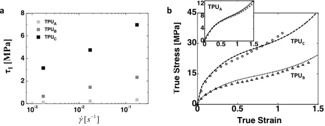
Figure 12 Representative data used for material parameter identification. (a) Shear yield stress as a function of strain rate in elastic-viscoplastic mechanism (experimental data) and (b) Stress-strain behaviors up to a true strain of 1.5 (open symbols: experiment, solid lines: model) at a strain rate of 0.001 /s
A
B 0,I B Ik
A s
G
q
æ
ö
=
×ç
÷
D
è
ø
B = s0,I− A⋅ ln !
γ
0,IpA
B IG
D
γ
!
0,Ip ss, Is
Ih
0 0.5 1 1.5 0 15 30 45 True Strain T ru e Str e s s [ M Pa ] 0 0.5 1 1.5 0 4 8 12 10-3 10-2 10-1 0 2 4 6 8 TPUA TPUB TPUC 1 [s ] g!-τ
I[M
Pa]
TPUB TPUCa
b
TPUA29 • Network mechanism (N)
The network mechanism, with or without softening, follows a time-independent equilibrium path in the stress-strain behaviors in many elastomeric materials. The relaxed stress-strain data upon cyclic deformation conditions are hence of importance for determining an individual stress contribution from the network mechanism. Guided by the procedures for determining the parameters for the network mechanism established by Boyce and coworkers [12, 15, 47], the elastic modulus, limiting chain extensibility and softening parameters were identified. Here we extensively used the stress-strain curves of TPUs with and without relaxation stages under multiple cyclic conditions of N = 1, 2, 3 and 4 for the
parametric studies of the network mechanism (See Figure 13). The initial elastic modulus ( ) in the
network mechanism was first determined using the stress-relaxation data at the imposed constant strains of 0.2 and 0.4 along with the elastic modulus in the elastic-viscoplastic mechanism since the elastic softening in the network mechanism was assumed to be small at these strains. The reloading curves in the final cycle (N = 4) in the multiple cyclic stress-strain data up to a large strain allowed us to estimate the
steady-state value ( ) of the network modulus. The reloading and unloading curves in the cyclic
stress-strain data at increasing strains indicate the shape of an elastic softening in the network mechanism,
and provided the rate parameter ( ) used in the evolution model for the limiting chain extensibility in
Equation (20). In particular, the equilibrium paths in relaxed stress-strain data under the multiple cyclic conditions (N = 1 and N = 4) can also provide quantitative estimations of the steady-state network modulus and the rate parameter (See Figure 13). Moreover the stress-strain data up to very large strains
give approximately the steady-state value ( ) of the limiting chain extensibility evolving
with deformation [38, 52], as shown in Figure 12b. Once the initial and steady-state values of the network elastic modulus and the steady-state value of the limiting chain extensibility were identified, the initial value of the limiting chain extensibility (or the number of effective Kuhn’s segments) was simply
0, N
µ
ss, Nµ
Nc
ss,lockN
ssl
º
30
determined using the constraint for and in Equation (19), i.e. . The initial elastic
modulus and limiting chain extensibility can be further validated by examining the cyclic stress-strain curves at small strains as detailed by Boyce and coworkers on the mechanical behaviors of polyureas under cyclic deformations with increasing strains [9, 10, 12].
Appendix B: Stress-strain behaviors of TPUs under multiple cyclic conditions with and without relaxation
The stress-strain data of all TPUs under multiple cyclic conditions are further presented in Figure 13. Figure 13a and Figure 13b show the stress-strain behaviors of TPUB under multiple cyclic loading conditions of N = 1, 2, 3 and 4 without and with relaxation stages, respectively (idling time between cycles: 120 s for both conditions). The stress-strain curves with relaxation stages were found to follow very well those without relaxation stages along the loading, unloading and recovery paths. Moreover hysteresis and shape recovery upon deformation with relaxation stages were found to be very similar to those without relaxation stages, including decreased dissipation due to lack of significant network softening in the subsequent cycles. The slightly softened stress responses in the subsequent cycles of N = 3 and 4, relative to that in N = 2, are attributed to an inelastic softening by the viscoplastic flows still sustaining in the elastic-viscoplastic mechanism. The inelastic softening in this mechanism was also found to result in a decreased relaxation as shown in the relaxed stress-strain curves in N = 2, 3 and 4; i.e., the stress contribution from the elastic-viscoplastic mechanism decreased due to the inelastic softening during the first cycle, which led to the decrease in the viscoplastic flow during the relaxation stages in the subsequent cycles. All of these features for hysteresis and relaxation weakened in the subsequent
stress-strain curves were observed again in Figure 13c and Figure 13d for TPUA and TPUC. This behavior
reveals that the time-dependent nature of the elastic-viscoplastic resistance in these materials.
N
µ
N
ss, N ss 0 0, NN
N
µ
µ
=
31 Furthermore, the equilibrium paths, which follow the average of the relaxed loading and unloading stress strain curves for N = 2, 3 and 4, show there is no significant network softening during these cycles; i.e., the equilibrium paths during these cycles superpose on the equilibrium unloading path in the first cycle.
Figure 13 Stress-relaxation data of TPUs under multiple cyclic conditions (N = 1, 2, 3 and 4) at a strain
rate of 0.01 /s. (a) Stress-strain curves of TPUB with no relaxation stages; relaxed stress-strain curves of (b)
TPUB; (c) TPUA; (d) TPUC; here the holding time for relaxation was taken to be 60 s and the idling time
for recovery (between cycles) was taken to be 120 s.
REFERENCE
[1] C. Hepburn, Reaction rates, catalysis and surfactants, Polyurethane elastomers, Springer1992, pp. 107-121.
[2] J.W. Cho, J.W. Kim, Y.C. Jung, N.S. Goo, Electroactive shape-memory polyurethane composites incorporating carbon nanotubes, Macromolecular Rapid Communications 26(5) (2005) 412-416.
[3] S. Kim, M. Spenko, S. Trujillo, B. Heyneman, D. Santos, M.R. Cutkosky, Smooth vertical surface climbing with directional adhesion, IEEE Transactions on robotics 24(1) (2008) 65-74.
[4] J.E. McBane, S. Sharifpoor, K. Cai, R.S. Labow, J.P. Santerre, Biodegradation and in vivo biocompatibility of a degradable, polar/hydrophobic/ionic polyurethane for tissue engineering applications, Biomaterials 32(26) (2011) 6034-6044.
[5] S.R. White, N. Sottos, P. Geubelle, J. Moore, M.R. Kessler, S. Sriram, E. Brown, S. Viswanathan, Autonomic healing of polymer composites, Nature 409(6822) (2001) 794-797.
[6] J. Wu, N. Wang, L. Wang, H. Dong, Y. Zhao, L. Jiang, Unidirectional water-penetration composite fibrous film via electrospinning, Soft Matter 8(22) (2012) 5996-5999.
[7] S.S. Sarva, S. Deschanel, M.C. Boyce, W. Chen, Stress–strain behavior of a polyurea and a polyurethane from low to high strain rates, Polymer 48(8) (2007) 2208-2213.
0 0.2 0.4 0.6 0.8 1 0 10 20 30 40 True Strain T ru e Str e s s [ M Pa ] 0 0.2 0.4 0.6 0.8 1 0 5 10 15 20 True Strain T ru e Str e s s [ M Pa ] 0 0.2 0.4 0.6 0.8 1 0 5 10 15 20 True Strain T ru e Str e s s [ M Pa ] N = 1N = 2 N = 3 N = 4 0 0.2 0.4 0.6 0.8 1 0 2 4 6 8 10 True Strain T ru e Str e s s [ M Pa ] TPUB TPUA a b c d TPUB TPUC