Publisher’s version / Version de l'éditeur:
Advanced Non-Destructive Evaluation Techniques for Polymer Based Composites in Military Vehicles (STO-MP-AVT-224), 2013-10
READ THESE TERMS AND CONDITIONS CAREFULLY BEFORE USING THIS WEBSITE. https://nrc-publications.canada.ca/eng/copyright
Vous avez des questions? Nous pouvons vous aider. Pour communiquer directement avec un auteur, consultez la première page de la revue dans laquelle son article a été publié afin de trouver ses coordonnées. Si vous n’arrivez pas à les repérer, communiquez avec nous à [email protected].
Questions? Contact the NRC Publications Archive team at
[email protected]. If you wish to email the authors directly, please see the first page of the publication for their contact information.
This publication could be one of several versions: author’s original, accepted manuscript or the publisher’s version. / La version de cette publication peut être l’une des suivantes : la version prépublication de l’auteur, la version acceptée du manuscrit ou la version de l’éditeur.
Access and use of this website and the material on it are subject to the Terms and Conditions set forth at
Laser ultrasonic, laser tapping and laser shockwave NDE technologies
for polymer based composites
Monchalin, Jean-Pierre; Néron, Christian; Padioleau, Christian; Lévesque,
Daniel; Blouin, Alain
https://publications-cnrc.canada.ca/fra/droits
L’accès à ce site Web et l’utilisation de son contenu sont assujettis aux conditions présentées dans le site LISEZ CES CONDITIONS ATTENTIVEMENT AVANT D’UTILISER CE SITE WEB.
NRC Publications Record / Notice d'Archives des publications de CNRC:
https://nrc-publications.canada.ca/eng/view/object/?id=3c312196-43e6-4734-91e6-29439755e648 https://publications-cnrc.canada.ca/fra/voir/objet/?id=3c312196-43e6-4734-91e6-29439755e648
Laser Ultrasonic, Laser Tapping and Laser Shockwave NDE Technologies
for Polymer Based Composites
Jean-Pierre Monchalin, Christian Néron, Christian Padioleau, Daniel Lévesque, Alain Blouin
National Research Council of Canada 75 Boulevard de Mortagne Boucherville, Québec, J4B 6Y4
CANADA
ABSTRACT
We are presenting the developments at the National Research Council of Canada of 3 laser-based inspection techniques for polymer-based composites. Laser-ultrasonics probes the material with ultrasound and useful for detecting delaminations, disbond in bonded assemblies and porosity. Laser tapping senses the vibrations induced by laser excitation and is useful detecting detachment and other defects in honeycomb and foam core structures. Laser shockwave testing is a non invasive proof test for adhesive bonds and provides an evaluation of bond strength.
1.0 INTRODUCTION
Polymer-based composite materials, due to their high stiffness-to-weight ratio and other properties, are more and more used in military vehicles, including airplanes, marine vessels and armour vehicles. Integrity of the structures of these vehicles requires nondestructive inspection or evaluation (NDE) at various times during the lifetime of the structures, from the manufacturing stage throughout the service period which may include or not use in battle situations. Even if there no combat use, damage could also occur (bird collision for airplanes, tool impact during maintenance ...). The structures may also degrade due to fatigue, water ingress ... In view of the limited funding available for replacing aging equipment by new ones, there are efforts in all NATO countries to extend the service life of many vehicles beyond the initially intended service life. These life extension programs require NDE to validate the safety of these extended life structures and all repairs or modifications done for this purpose.
We report here developments at the National Research Council of Canada (NRC) of Laser-based ultrasound and related techniques, Laser Ultrasonics, Laser Tapping and Laser Shockwave and their application to the NDE of polymer-based composites. Laser Ultrasonics and Laser Tapping aim at detecting flaws in the materials, such as delaminations, disbonds or porosity, whereas Laser shockwave is a proof test technique for evaluating the strength of an adhesive bond.
2.0 LASER ULTRASONICS
Laser-ultrasonics is an established ultrasonic inspection technique that uses lasers for the generation and detection of ultrasound [1]. As shown in Figure 1, two laser beams essentially collinear are scanned on the part to be inspected. The generation laser beam produces non-destructively, by thermoelastic effect, a stress at
the surface of the part, which in turn produces an ultrasonic wave launched normally to the surface, independently of its shape and of the laser beam orientation. Ultrasonic waves reflected or scattered by the back wall or flaws are detected by the detection laser beam and an optical interferometer (confocal Fabry-Perot, photorefractive interferometer), which senses the Doppler shift of the scattered light produced by the ultrasonic surface motion. Received signals are essentially processed as in conventional immersion ultrasonics to display C-scans, B-scans and A-scans.
Optical scanning Generation & detection lasers Optical scanning Generation & detection lasers Optical scanning Generation & detection lasers
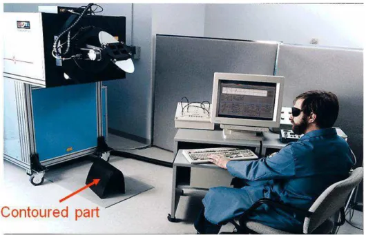
Figure 1: Principle of Laser-ultrasonics for contoured part inspection
NRC and its first licensee for the technology UltraOptec made the first prototype system for this application. This system used a TEA CO2 laser for generation of ultrasound and a specially developed high stability long Nd-YAG laser for detection coupled to confocal Fabry-Perot interferometer. This system built in 1993 is still in use at the EADS-Airbus development centre in Nantes, France: see Figure 2. UltraOptec and NRC made also a turnkey production system for the US Air Force base in Sacramento. This system allowed the inspection of wing size part by mounting the mirror scanning inspection unit with the CO2 generation laser on a gantry robot to index scan from locations about a meter apart: see Figure 3. The systems currently in use at Lockheed Martin Forth Worth for inspecting F22 and F35 manufactured parts have a similar overall configuration. The technology has also been demonstrated in service inspection: see Figure 4, which shows a first generation system inspecting the fuselage of a CF18 in a maintenance hangar and the C-scan of the horizontal stabilizer.
More recent developments at NRC in this area include the development of a system for inspecting big barrel fuselages parts made by Automatic Fibre Placement (jointly with Tecnar Automation, a current licensee of NRC) and addressing the limitation caused by very shinny or mirror-like surfaces at detection. A view of the system for large fuselage inspection is shown in Figure 5. The concept used was to mount the large front end unit which includes the scanning mirror and the CO2 laser at the end of a long cantilever beam extending from a strong pivot anchored to the plant floor. For inside inspection, the barrel is inserted into the cantilever structure. Since the scanning mirror can scan 360º by +/-30º a large area all around the barrel can be inspected from a given position of the unit. Additional rotational degree of freedom for the inspection head was added for inspecting efficiently longitudinal or circumferential stiffeners, as well as the cockpit area which is not cylindrical. The system also includes a movable enclosure insuring ocular safety for inspecting smaller parts which are not shaped as a large barrel.
In the case of very shiny surface, nearly the whole intensity of the detection laser beam is steered in a direction different from the incident direction, which leaves very little light back scattered and, in turn, results in a poor
sensitivity. This problem was solved by two approaches. In the first one, the co-linear generation and detection beams are directed normally to the surface by robotic control: see Figure 6 for 2 implementations, one at NRC and the other one in its vicinity. In these implementations, there is no scanning mirror, the scan being done by the robot itself. Rapid scanning is made possible by having a front inspection head small and light to minimize inertia.
As shown in Figure 7, the second approach consists in retro-reflecting light onto the surface and along the direction of the incident beams. Figure 8 shows results demonstrating this approach obtained on a U-shaped part with shiny surfaces.
Figure 2: First laser ultrasonic system for composite inspection: only the unit of the system which includes the mirror scanner and the CO2 laser is shown here scanning a contoured part on the floor. The detection unit which includes the detection laser and the interferometer is coupled with long optical fibres and remotely located.
Figure 3: Left: sketch of the inspection system installed at the McClellan Air Force base in Sacramento CA, (now dismantled); Right: picture of the inspection head at the end of the gantry robot mast inspecting a composite part.
Figure 4: Demonstration of in-service inspection of a CF18 by laser ultrasonics. Left: System installed next to the plane; a folding mirror was used to steer the beams for inspection from underneath the structure; Right: C-scan of the horizontal stabilizer, not the inspection to very edge of the part.
Figure 5: Laser ultrasonic inspection system located at Mirabel near Montreal for fuselage inspection. Left: View of inspection head which includes the scanning mirror and coupling/ collection optics at the end of the cantilever inside a front fuselage section. Right: cantilever beam and its pivot. The large TEA CO2 laser is located on top of the pivot and then channelled along the cantilever beam length. The detection laser and interferometer which are not seen in these pictures are optical fibre coupled and remotely located.
Figure 6: Robot guided laser ultrasonic inspection systems. Left: system at NRC, Right: system made by Tecnar Automation licensee of NRC and installed at Centre Technologique en Aérospatiale near Montreal. The CO2 laser beam is transmitted by an articulated arm (seen in both pictures) whereas the detection laser beam and the light reflected by the surface are transmitted by optical fibres.
Retro reflecting surface: tape , paint, paper
Without
Amplitude Time-of-flight
Figure 8: Laser ultrasonic inspection of a corner of a U-shaped part with mirror-like surfaces, Above: picture of the part with indication of the scanned region, Below: time-of-flight and amplitude C-scans showing implanted defects with the retro-reflecting screen. The poor quality small images on the left show the time-of-flight and amplitude C-scans (in the identified regions at right) obtained without the retro-reflecting screen.
3.0 LASER TAPPING
Laser Tapping, which is sketched in Figure 9, uses essentially the same hardware as laser-ultrasonics but instead of exploiting the high frequency contents of the signal (ultrasonic frequencies, typically from 1MHz to 15 MHz for composites) exploits lower frequencies (typically 20kHz to 1MHz). These low frequencies are indicative of some detachment on the part, the detached part vibrating like a membrane following the thermoelastic deformation produced by the generation laser and the associated bending moment. Laser tapping is therefore similar to a conventional tap test. Alternatively the vibration can be seen resulting from acoustic Lamb waves that are reverberating within the detached membrane.
Laser Tapping is very useful for detecting skin disbond in honeycombs or foam core parts. We present as example in Figure 10 the mapping of the delaminations produced by impact on a Nomex honeycomb part. As we can see the technique is able to map out skin detachment on the impacted side as well as on the opposite side. The technique has also be shown to be able to detect crushed honeycomb core.
Laser tapping can be applied concurrently to Laser ultrasonics. For optimum sensitivity of the technique, it is advantageous to use a detection interferometer with good response at low frequencies, i.e. a photorefractive interferometer, although a confocal Fabry-Perot can be used with reduced sensitivity.
Optical
scanning
Figure 9: Sketch of Laser Tapping used to inspect a honeycomb structure.
14 KHz 59 KHz
Scan on the impacted side
Scan on the back side
side. The image obtained by scanning over the back side (opposite to impact) appears as expected as a mirror image of the one obtained by scanning over the impacted side.
4.0 LASER SHOCKWAVE PROOF TESTING
The two techniques mentioned above allow the detection of flaws and in the case of an adhesively bonded assembly the detection of disbonds, but they cannot detect a weak bond. In the case of ultrasonic interrogation, by laser or piezoelectric transducer, the response is the same whether the bond is strong or weak (even very weak, as the so-called kissing bond) as far as there is contact between the 2 adherents. Laser Tapping and shearography (by thermal excitation or vacuum) produces a lifting force but this force is weak, typically about or slightly higher the atmospheric pressure (about 0.1 MPa) and not able to reveal a weak bond with strength of several MPa. All the other existing NDE techniques also fail.
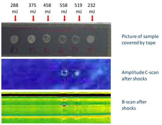
The Laser shockwave proof testing technique allows on the other hand applying a strong pulling force across the bond that reveals inadequate bond strength. The principle of the technique is sketched in Figure 11. It uses a high energy laser that produces a strong compressive wave converted into tensile wave by reflection from the back wall. The technique is non-invasive unless the bond is weak and below the desired strength. By measuring with a specially developed interferometer the back wall velocity and using a model of stress propagation in the bonded assembly, the stress applied on the bond line and the bond strength at the high tensile rate provided by the technique can be calculated. The laser loading is increased step by step until an indication of bond breakage is observed on the velocimeter. Bond rupture is verified by post-shock ultrasonic or laser ultrasonic inspection. We present as example in Figure 12-14, the results obtained on an assembly including 8-ply over 8-ply laminates bonded with a weaken adhesive. Techniques to make weak bonds have been developed and efforts to correlate the results obtained by the Laser shockwave technique at high tensile rate with standard destructive tests have been started. LASER Adhesive Laser Interferometer(velocimeter) Plasma Tensile wave Compression wave Black tape Water confinement O-ring LASER
Figure 11: Left: principle of the laser shockwave technique for proof testing bond strength, Right: configuration for protecting the surface from damage and applying a strong pressure by confining the plasma with water
Figure 12a: Normalized back surface velocity signals for increasing laser energy loading. Superposition of all the signals before rupture (seen at 519 and 558 mJ) indicate propagation in the elastic regime. 288 mJ 375 mJ 458 mJ 558 mJ 519 mJ 232 mJ Picture of sample covered by tape Amplitude C-scan after shocks B-scan after shocks
From model
Figure 12c: Velocity signals below and above threshold and result of a model predicting the stress history at the bond line. For this test specimen beakage occurs at about 1.15 µs under a tensile stress of about 150 MPa.
5.0 SUMMARY AND CONCLUSION
We have presented 3 laser-based techniques for NDE of polymer-based composites, which should respond to the inspection needs for service and life extension of many military vehicles (airplanes, marine vessels, armour vehicles ...).
REFERENCES
[1] J.-P. Monchalin, Laser-Ultrasonics: Principles and Industrial Applications, Chapter 4, pp. 79-115, in “Ultrasonic and Advanced Methods for Nondestructive Testing and Material Characterization”, C.H. Chen Ed., World Scientific Publishing Co., 2007
[2] A. Blouin, C. Néron, B. Campagne and J.-P. Monchalin, Applications of laser tapping and laser ultrasonics to aerospace composite structure, Insight 52, 130, (2010)
[3] A. Blouin, C. Néron and J.-P. Monchalin, Laser-ultrasonics and laser- tapping for the inspection of aerospace composite structures, Proceedings of the Eight Joint Canada-Japan Workshop on Composites, (2010)
[4] M. Perton, A. Blouin and J.-P. Monchalin, Adhesive bond testing of carbon–epoxy composites by laser shockwave, J. Phys. D: Appl. Phys. 44, 034012, (2011).
[5] J.-P. Monchalin, M. Perton, D. Levesque, A. Blouin, M. Lord, G. Rousseau, R. Cole, “ Adhesive Bond
testing between Composite Laminates by Laser Shockwave Loading”, Procceding of the 19th International Conference on Composite Materials ICCM19, Montreal, July28-August 2, 2013