Publisher’s version / Version de l'éditeur:
Vous avez des questions? Nous pouvons vous aider. Pour communiquer directement avec un auteur, consultez la première page de la revue dans laquelle son article a été publié afin de trouver ses coordonnées. Si vous n’arrivez pas à les repérer, communiquez avec nous à [email protected].
Questions? Contact the NRC Publications Archive team at
[email protected]. If you wish to email the authors directly, please see the first page of the publication for their contact information.
https://publications-cnrc.canada.ca/fra/droits
L’accès à ce site Web et l’utilisation de son contenu sont assujettis aux conditions présentées dans le site LISEZ CES CONDITIONS ATTENTIVEMENT AVANT D’UTILISER CE SITE WEB.
IEEE Ultrasonics Symposium [Proceedings], pp. 1516-1519, 2008-11-01
READ THESE TERMS AND CONDITIONS CAREFULLY BEFORE USING THIS WEBSITE. https://nrc-publications.canada.ca/eng/copyright
NRC Publications Archive Record / Notice des Archives des publications du CNRC :
https://nrc-publications.canada.ca/eng/view/object/?id=fe1116b0-a9dd-4929-b0bc-ddcba7c4fd82 https://publications-cnrc.canada.ca/fra/voir/objet/?id=fe1116b0-a9dd-4929-b0bc-ddcba7c4fd82
NRC Publications Archive
Archives des publications du CNRC
This publication could be one of several versions: author’s original, accepted manuscript or the publisher’s version. / La version de cette publication peut être l’une des suivantes : la version prépublication de l’auteur, la version acceptée du manuscrit ou la version de l’éditeur.
For the publisher’s version, please access the DOI link below./ Pour consulter la version de l’éditeur, utilisez le lien DOI ci-dessous.
https://doi.org/10.1109/ULTSYM.2008.0369
Access and use of this website and the material on it are subject to the Terms and Conditions set forth at
NDE using laser generated ultrasound and integrated ultrasonic
transducer receivers
NDE Using Laser Generated Ultrasound and
Integrated Ultrasonic Transducer Receivers
C.-K. Jen1, K.-T. Wu2 , M. Kobayashi1 and A. Blouin1
1. Industrial Materials Institute, National Research Council of Canada,
Boucherville, Québec, Canada J4B 6Y4. Email: [email protected] 2. Department of Electrical and Computer Engineering, McGill University,
Montreal, Quebec, Canada H3A 2A7
Abstract—Non-destructive evaluation (NDE) of parts using laser generated ultrasound and integrated ultrasonic transducers (IUTs) as receiver is presented. Pulsed laser represents a versatile ultrasound generation transducer. Sol-gel fabricated thick piezoelectric film IUTs coated directly onto steel, aluminum (Al) and graphite/epoxy (Gr/Ep) composites substrates with planar or curves surfaces serve as efficient ultrasonic receivers without the need of couplant. Ultrasonic NDE of metals and Gr/Ep composite using laser generation in the thermoelastic or ablation regime and IUT receiving in longitudinal bulk waves, symmetric or shear-horizontal plate acoustic waves has been carried out.
Keywords- NDE; integrated ultrasonic transducers; laser ultrasound; piezoelectric thick films; sol-gel process; composite
I. INTRODUCTION
NDE and health monitoring [1-3] of structures becomes increasing interest to aerospace and power generation community when considering aging aircrafts or power plants whose growing maintenance costs can reduce their economic life extension. Also emerging new airplanes and power plants are progressively more required to be equipped with intelligence for improved diagnostics of the health condition of the critical parts and structures.
Therefore, there are demands for novel NDE or structural health monitoring (SHM) techniques for local and global (long distance) damage diagnostics.
Using pulsed lasers to generate ultrasound is an attractive and effective non-contact method in which the laser and the object may be meters away [4-6]. Other merits include the ability to perform NDE of materials having curved surfaces and at high temperatures. Furthermore laser beams can be considered as versatile UTs which may have adjustable transducer size, shape, and power and be arranged in array configuration and scanned in a reasonable speed using mirrors.
Recently sol-gel fabricated piezoelectric thick (>40μm) films have been demonstrated being able to be coated onto planar and curved surfaces of steel, aluminum (Al) and graphite/epoxy (Gr/Ep) composite substrates as integrated IUTs [7-9]. Such miniature and light weight IUTs were
successfully used in pulse/echo or transmission mode at room and elevated temperatures. The objective of this investigation is to explore the merits of combining the usage of pulsed lasers as the ultrasound generating UTs with that of IUTs as the receivers.
II. IUTFABRICATION AND RECEIVER SENSITIVITY
EVALUATION
A. IUT Fabrication
The piezoelectric composite film fabrication is based on a sol-gel spray technique [6]. It mainly consists of six steps [7-9]; (1) preparing high dielectric constant lead-zirconate-titanate (PZT) solution, (2) ball milling of piezoelectric PZT ceramic powders to submicron size, (3) sensor spraying using slurries from steps (1) and (2) to produce the thin PZT-composite (PZT-c) film, (4) heat treating to produce a thin solid PZT-c ceramic film, (5) corona poling to obtain piezoelectricity, and (6) electrode painting for top electrodes which define the IUT active area. Metal substrate itself serves as the bottom electrode of IUT. Steps (3) and (4) are used multiple times to produce optimal film thickness for specified ultrasonic operating frequencies of IUTs. The chosen top electrode fabrication approach enables to achieve desired sensor configurations including arrays conveniently.
B. Receiver Sensitivity
Fig.1a shows an IUT made of 90μm thick PZT-c film and deposited onto a 12.7mm thick steel plate and measured by a handheld EPOCH model LT pulser-receiver (from Olympus-Panametrics, USA) at room temperature. EPOCH LT is commonly used for NDT by many industries. The diameter of the top silver paste electrode of this IUT is 5.5mm. The measured ultrasonic data in pulse-echo mode is also presented in Fig.1b, where Ln is the nth trip L echo through the plate thickness. The centre frequency and the 6dB bandwidth of L2 echo are 14.6 and 15.5MHz respectively. In Fig.1b 0dB gain out of the available 100dB receiver gain was used. The signal to noise ratio (SNR) of the L2 echo is 46dB. When commercial broad bandwidth UTs with a center frequency at 5MHz and Digital Object Identifier: 10.1109/ULTSYM.2008.0369
10MHz are used at the other side of the steel plate shown in Fig.1a together with the necessary ultrasonic couplant, the measured results are shown in Figs. 2a and 2b, respectively. The receiver gains used by the EPOCH pulser/receiver were 2dB and 4.5dB, respectively. It means that the IUT performs a slightly better than the two commercial purchased broad bandwidth UTs. Thus this L wave IUT is efficient.
12.7 mm thick steel Ln: nth trip echo through the thickness L2 L4 L6 L8 PZT-c IUT (a) 5 10 15 20 Amp lit u d e ( a rb . unit ) Time Delay (μs) L2 L4 L6 L8 (b)
Figure 1. (a) Measurement setup for an IUT made of PZT-c film using a EPOCH LT in pulse-echo mode; (b) Measured ultrasonic signals at room temperature. 5 10 15 20 Amp lit u d e ( a rb . u n it ) Time Delay (μs) L2 L4 L6 L8 (a) 5 10 15 20 Am plit u d e ( a rb . u n it ) Time Delay (μs) L2 L4 L6 L8 (b)
Figure 2. Measured ultrasonic signals of commercial UTs with a center frequency of (a) 5MHz and (b) 10MHz operated in pulse/echo mode at the opposite surface of the steel plate coated with IUT.
III. PULSED LASER GENERATION AND IUTRECEIVING
For this study a pulsed laser (λ=1.06μm) with pulses of 45mJ energy and 5ns duration delivered at a repetition rate of 10Hz is used for the generation of ultrasound.
A. L Wave in Steel Plate
Figs. 3a and 3b show the schematic diagram and measurement setup, respectively, of the ultrasonic measurement using the IUT coated onto the steel plate shown in Fig.1a to receive the laser generated ultrasound in the steel plate. The laser generation location is at the opposite side of the steel plate but located at the center of the IUT (top electrode). Fig. 3b showed the measured ultrasonic signal displayed in an oscilloscope without any amplification. The laser spot size was 8mm diameter and the energy is in the thermoelastic regime [4-6]. Excellent SNR of the echoes L1 and L3 is also demonstrated. IUT Laser Generator Oscilloscope Trigger signal RF signal Laser beam (a) IUT Laser Beam L1 L3 (b)
Figure 3. (a) Schematic and (b) measurement setup of laser generation and IUT receiving in a steel plate.
B. Plate Acoustic Waves (PAWs) in Al Plate
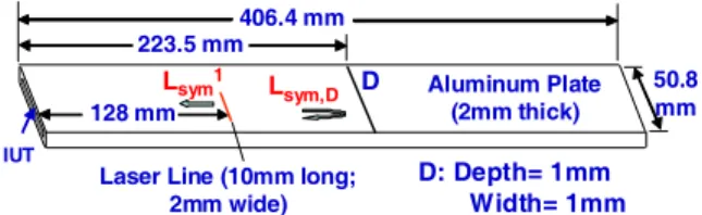
When an L wave IUT is coated onto the edge of a thin Al plate as shown in Fig.4, symmetrical PAW may be generated [9]. This Al plate has a length of 406.4mm, width of 50.8mm and a thickness of 2mm. One artificial line defect, D with 1mm depth, 1mm width and 50.8mm length was made for the demonstration of the ability of symmetrical PAW to detect such defect. For the measurement the IUT has a top electrode with a height of 1.8mm and a width of 48mm. The thickness of the PZT-c film was 88μm. Using a line laser beam of 10mm long and 2mm wide to impinge onto the Al plate at the location indicated in Fig.4, the measured ultrasonic signals are shown in Fig.5. Since this L wave IUT centered at nearly 5MHz can receive predominantly symmetric PAWs due to the thinness of the plate, the received signals shown in Fig.5 are mostly symmetrical PAWs with many higher order modes. The measured arrival time of the signals also support such understanding. It means that laser beam can generate sufficient symmetrical PAWs for this IUT to receive. In Fig.5 defect D is clearly observed. 50.8 mm 406.4 mm IUT Aluminum Plate (2mm thick) 128 mm D Lsym1 Lsym,D 223.5 mm
Laser Line (10mm long; 2mm wide)
D: Depth= 1mm Width= 1mm
Figure 4. Sample and measurement arrangement for symmetrical PAWs.
0 50 100 150 200 A m plit ud e ( a rb . u n it ) Time Delay (μs) Lsym1 Lsym,D
Figure 5. Measured ultrasonic signals at room temperature.
In Fig.6 an IUT made of 90μm thick PZT-c film with a top electrode area of 1.6mm in height and 20mm in length as the receiver is coated onto the side near the edge of the a 2mm thick, 50.8mm wide and 406.4mm long Al plate. A mode conversion angle θ = 61.7° is used to convert the lowest order
symmetrical PAW, S0, to the lowest order shear-horizontal
(SH) mode, (SH0) and vice versa [9]. Such mode conversion is
similar to that from L wave to shear (S) and vise versa [10, 11]. One defects, D’ is also made and its dimensions and locations are the same as D described earlier except that D’ has a depth of 0.95mm. The schematic of a laser line generation and IUT receiving for SH PAWs is shown in Fig.6. The line width of the laser beam was 2mm and the length was 10mm. The measured ultrasonic signals are shown in Fig.7. In Fig. 7 the signals are predominantly SH PAWs. The measured time delay of these signals also supports such explanation. One can see that defect D’ can be clearly identified. It also indicates that laser beam can generate sufficient SH PAWs for IUT shown in Fig. 6 to receive. 61.7° 50.8 mm 406.4 mm IUT Aluminum Plate (2mm thick) 125 mm 223.5 mm
Laser Line (10mm long;
2mm wide) D’
D: Depth= 0.95mm Width= 1mm
SH1
SHD
Figure 6. Sample and measurement arrangement for symmetrical PAWs.
0 50 100 150 200 Am p lit u d e ( a rb . u n it ) Time Delay (μs) SH1 SH,D’
Figure 7. Measured ultrasonic signals at room temperature.
C. L Waves in Gr/Ep Composites
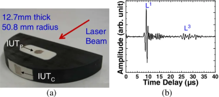
IUT can be also directly deposited onto Gr/Ep composites. If the Gr/Ep has sufficient electrical conductance then itself like the metal can be used as bottom electrode of IUT, otherwise a thin (~2μm) conducting film such as silver paste made by colloidal silver spray can be deposited on the Gr/Ep composite first as the bottom electrode of IUT. The same fabrication method described in Section II is used to complete the IUT fabrication. Fig.8a shows that one IUTP and one IUTC
are coated onto the planar and curved surfaces, respectively of a semi-circular shaped Gr/Ep composite with a thickness of 12.7mm and a radius of 50.8mm. This composite was made of 0° and 90° cross plies. The measured resistivity on the composite top surface was 0.72Ω-m which is low enough to serve as the bottom electrode of IUT. The top electrode shape is chosen arbitrarily, and the top electrode size of the IUTP and
that of IUTC are 7.5mm diameter and 6mm by 7mm,
respectively. Since Gr/Ep composite can only expose to a temperature up to 175°C during the fabrication, the thermal treatment temperature of the PZT-c film in this study is also up to 175°C. Because of such a low heat treatment temperature, the strength of these IUTs is about 60dB weaker than that of the IUT on steel plate shown in Fig.1.
Fig. 8a also shows the configuration of laser generation and IUTP receiving experiment. The laser beam impinges at a
location at the center of IUTP but at the opposite position of the
composite plate. It is in transmission mode. The laser beam spot was 6mm diameter. It is in the thermoelastic mode. The measured ultrasonic signal is shown in Fig.8b. The center frequency and 6dB bandwidth of the L1 echo were 1.5MHz and 2.2MHz, respectively. 12.7 mm thick 50.8 mm radius IUTP IUTC Laser Beam 12.7 mm thick 50.8 mm radius IUTP IUTC Laser Beam (a) 0 5 10 15 20 25 30 35 40 A m pl it ude (a rb . uni t) Time Delay (μs) L1 L3 L5 L7 (b)
Figure 8. (a) Configuration of laser generation IUTp receiving on a Gr/Ep composite (b) Measured ultrasonic signal..
The schematic of laser generation and IUTC receiving
experiment is given in Fig.9a. The laser beam impinges at a location at the center of IUTC but at the center of the opposite
flat plane. This is a transmission mode measurement configuration. The laser beam spot was 6mm diameter. It is also in the thermoelastic mode. The measured ultrasonic signal is shown in Fig.9b. The center frequency and 6dB bandwidth of the L1 echo were 1.2MHz and 1.5MHz, respectively.
12.7mm thick 50.8 mm radius IUTP IUTC Laser Beam 12.7mm thick 50.8 mm radius IUTP IUTC Laser Beam (a) 0 5 10 15 20 25 30 35 40 Amp lit u d e ( a rb . u n it ) Time Delay (μs) L1 L3 (b)
Figure 9. (a) Configuration of laser generation IUTC receiving on a Gr/Ep composite (b) Measured ultrasonic signal.
The measured ultrasonic velocitioes in this composite along the thickness and radial direction are 2883m/s and 6051m/s, respectively. The difference comes from the anitropy of the composite. It also means that NDE of materials can be carried out using laser generation and IUT detection of ultrasound.
IV. CONCLUSION
Ultrasonic NDE of steel, Al and Gr/Ep composites using laser generation and IUT detection of ultrasound has been presented. A pulsed laser (λ=1.06μm) with pulses of 45mJ energy and 5ns duration delivered at a repetition rate of 10Hz with different spot sizes and shapes was used for the generation of ultrasound. IUTs were made of a sol-gel sprayed technique. When the IUT was coated onto a steel plate, the received
ultrasonic signal of good SNR did not need amplification even the laser generation was in the thermoelastic regime. Using a laser line beam source in the ablation regime the detection of the line defect parallel to the line source in two Al plates was also demonstrated using symmetrical and SH PAWs. This demonstrates that long distance NDE can be performed. It was also shown that IUTs can be made onto the planar and curved surfaces of a Gr/Ep composite. NDE of anisotropy of this composite using laser generation in the thermoelastic regime and IUT detection was also demonstrated. Since IUTs are miniature in size and light weight and they may have sufficient high sensitivity similar to commercially available broad band UTs and are used only as receivers, operation in long life using battery and energy-harvested energy is expected. As both laser generation and IUT can be used for curved surfaces and high temperature operation, possibilities for NDE of large and complex structures in harsh conditions may be possible [12].
ACKNOWLEDGMENT
Financial support from the Natural Sciences and Engineering Research Council of Canada is acknowledged.
REFERENCES
[1] M.V. Gandhi, and B.S. Thompson, Smart Materials and Structures, London; New York, Chapman & Hall, 1992.
[2] J.-B. Ihn, and F.-K. Chang, “Ultrasonic Non-destructive Evaluation for Structure Health Monitoring: Built-in Diagnostics for Hot-spot Monitoring in Metallic and Composite Structures”, Chapter 9 in
Ultrasonic Nondestructive Evaluation Engineering and Biological Material Characterization, edited by T. Kundu, CRC Press, NY, 2004. [3] A.S. Birks, R.E. Green, Jr. and P. McIntire, ed., Nondestructive Testing
Handbook, 2nd Ed., vol.7: Ultrasonic Testing, ASNT, 1991.
[4] R.M. White, R.M., “Generation of elastic waves by transient surface heating,” J. Appl. Physics, vol.34, pp.3559-67, 1963.
[5] Scruby, C.B., Dewhurst, R.J., Hutchins, D.A., and Palmer, S.B., “Laser generation of ultrasound in metals,” in Res. Techniques in Nondestructrive Testing, vol.5, R.S. Sharpe, Ed. New York: Academic Press pp.281-327, 1982.
[6] Hutchings, D.A., “Ultrasonic generation by pulsed lasers,” in Physics Acoustics, vol.18, W.P. Mason and R.N. Thurston, Ed. New York: Academic Press, pp.21-123, 1988.
[7] D. Barrow, T.E.. Petroff, R.P. Tandon, and M. Sayer, “Chracterization of thick lead-zirconate titanate films fabricated using a new sol gel process,” J. Apply. Phys., vol.81, pp.876-881, 1997.
[8] M. Kobayashi and C.-K. Jen, “Piezoelectric thick bismuth titanate/PZT composite film transducers for smart NDE of metals,” Smart Materials and Structures, vol. 13, pp. 951-956, 2004.
[9] K.-T. Wu, C.-K. Jen and M. Kobayashi, “High temperature integrated plate acoustic wave transducers,” Elect. Letts., vol.44, pp.776-7, 2008. [10] M.O. Si-Chaib, H. Djelouah and M. Bocquet, “Applications of
ultrasonic reflection mode conversion transducers in NDT,” NDT&E Int’l, vol.33, pp.91-99, 2000.
[11] C.-K. Jen, Y. Ono and M. Kobayashi, “high temperature integrated ultrasonic shear wave probes,” Applied Phys. Lett., vol.89, pp.183506_1 to 3, 2006.
[12] J.-R. Lee, J. Takatsubo, N. Toyama and D.-H. Kang, “Health monitoring of complex curved structures using an ultrasonic wavefield propagation imaging system,” Measurement Science and Tech., vol.18, pp. 3816-3824, 2007.