Investigation on the structure of carbonized pitch and calcined coke-carbonized pitch interface in carbon anodes by etching
Xianai Huang*1, Duygu Kocaefe1, Ying Lu1, Dipankar Bhattacharyay1, Yasar Kocaefe1, Patrick Coulombe2
1 University of Quebec at Chicoutimi 555
Boulevard de l'Université, Chicoutimi, QC, Canada G7H 2B1
2Aluminerie Alouette Inc., 400, Chemin de la Pointe-Noire, Sept-Îles, Québec, Canada G4R 5M9 Xianai Huang <[email protected]>,
Duygu Kocaefe <[email protected]>, Ying Lu <[email protected]>,
Dipankar Bhattacharyay < [email protected] >
Yasar Kocaefe<[email protected]>, Coulombe Patrick <[email protected]>
Corresponding author: Tel 1 418-545 5011 ext. 2414. E-mail: [email protected]
Abstract: A novel, simple, quick and economic method has been developed to etch samples for characterizing the structural aspects of carbonized pitch alone and in baked anodes. Hot air is employed to etch the polished carbonized pitch surface for creating its topography; followed by the characterization of the structure using scanning electron microscope. Hot air preferentially etches the carbonized pitch, which make the differentiation of carbonized pitch from the calcined coke particles possible in baked anode. After etching, lamellar parallel cracks are created and fine granular mosaics are observed on the surfaces of carbonized pitch. The structural composition in baked anode differs visibly from the pure carbonized pitch baked under the same conditions. This may be due to the effect of fine coke particles in anode on the formation of structure during baking. The etching technique permits the determination of the internal structure of carbonized pitch and its interface with coke in anode.
Keywords: carbon anode, etching, structure, carbonized pitch, SEM, interface
1.Instruction
Coal tar pitch is an anode raw material which binds the coke particles together during the production of carbon anodes used in aluminum industry. During the baking process, pitch undergoes pyrolysis. The thermal decomposition of pitch results in the release of volatiles and the formation of pitch coke, namely, carbonized pitch. Carbonized pitch exhibits different structure than that of coke due to its properties, mixing and compacting conditions used as well as the heat treatment that it is subjected to during anode fabrication. The structure of carbonized pitch and its interface with coke particles have a significate influence on the strength and reactivity of baked anodes 1, 2.
Polarized light microscopy is a well-known method which is used for the examination of polished surfaces of metallurgical cokes 3-10. Optical textural units of varying size and color can be seen on the polished coke surface due to the interaction between the structure and the incident light 4. Two types of optical structure of carbonized pitch (isotropic and anisotropic) can be identified by optical microscopy depending on pitch composition and baking conditions. The granular texture in carbonized pitch under polarized light exhibits stronger physical bonding with coke due to stronger possibility of forming chemical bond with coke particles compared to that of carbonized anisotropic pitch. Therefore, carbonized pitch with relatively granular structure is preferred for anode production due to more favorable anode strength 11, 12. Moreover, disordered carbonised coke has less open porosity which protects the underlying coke from air/CO2
oxidation better than a more ordered anisotropic carbonised coke in addition to obtaining anode with better strength with this type of pitch 1, 2. Because of the similar hardness and composition of coke and carbonized pitch in baked anodes, their optical shapes and structures are similar.
This makes it difficult to distinguish carbonized pitch from the coke particles and to identify their interface on the polished surface of the sample by this technique.
Scanning electron microscopy (SEM) is also used to characterize the structure of different metallurgical cokes 3, 4, 6, 9 and carbonized pitches 3, 5 on fractured or etched surfaces. SEM examination on fractured surface can reveal the true three-dimensional nature of texture but cannot quantify its textural composition. This can be successfully determined by examining the etched surfaces with a point-counting technique, which facilitates the correlation of textural composition with carbon properties. The principle of etching technique is based on the etchants’
preferential reaction with carbon materials, which creates various morphological characteristics.
Therefore, the choosing the type of etchant and etching conditions is critical to produce a suitable surface for SEM examination.
Various etchants were used to etch coke and carbon material surfaces for SEM examination.
Argon ion was used successfully as an etchant for polished coke surfaces by Patrick et al 9. Etching of coke fibers in oxygen plasma is reported by Bernet and Norr 13. Atomic oxygen, a useful and traditional etchant for cokes and carbon materials, was utilized by several researchers to characterize the structure of carbons and graphite 3-6. Atomic oxygen reacts preferentially with the optical isotropic texture in metallurgical coke 6. The carbon textural constituents observed by microscopy on the etched surface using atomic oxygen correlated well with the coke strength 4. Etching of baked anode by atomic oxygen provided textural information on carbonized pitch which served to explain the mechanical properties of the corresponding laboratory anode 3, 5. Coke and carbonized pitch as well as the textural composition of carbonized pitch were successfully identified and differentiated in these studies. However, the anodes used were made of fine petroleum coke with a narrow range of particle size distribution (+75 -150 µm) in the
laboratory. The commercial carbon anodes containing coke particles with a wide range of particle size distribution were not studied. The strong oxidizer, chromic acid, was also used as etchant to obtain cokes and carbon surfaces and compare with those etched using atomic oxygen
6. The study revealed that chromic acid oxidized preferentially the anisotropic carbon whereas atomic oxygen etched better the isotropic carbon.
There are different terms (anisotropic, lamellar, isotropic, and granular) to describe the texture of coke and carbonized pitch in literature 3-6. The terms isotropic and granular, are used for the similar pitch textures. In this article, granular was used to represent this type of structure.
Although the etchants stated above are suitable to etch carbon materials, most of them need specific and expensive apparatus, which are not available in most laboratories. In addition, the chemicals used such as chromic acids are toxic and carcinogenic and difficult to dispose after etching. Therefore, the object of the present study is to develop a simple, fast, cheap and convenient method for etching baked anode surfaces to facilitate the structural analysis. To obtain information on carbonized pitch structure, air etching experiments were carried out.
Mildly oxidizing conditions were used to remove the less etch resistant portions of the carbon and to expose the more resistant crystalline structure so that it can be analyzed with a scanning electron microscope. An attempt was made to compare the textures of carbonized pitch on fractured, polished and etched surfaces using SEM with the aim of identifying suitable etching technique. The differences in the textures and topography of pure carbonized pitch as well as carbonized pitch and its interface with coke in baked anodes, which were produced in the laboratory using an anode recipe similar to that of industry, were investigated.
2.Experimental 2.1Carbon materials
Anode was produced in the laboratory using an anode recipe similar to that used in industry.
The chemical and physical properties of coal tar pitch and fresh petroleum coke are presented in Table 1. The commercial petroleum coke, butt, recycled anodes and coal tar pitch were mixed at a certain temperature and the anode paste was vibro-compacted to obtain green anode. Then, the anode covered by packing coke was baked in a furnace available at the carbon laboratory of the University of Quebec at Chicoutimi (UQAC). The anodes were baked using heating rate of 11
°C/h and a soaking time of 8 h at the maximum temperature of 1100 °C. The same coal tar pitch, used as binder in anodes, was also carbonized alone (pure carbonized pitch) in an electrically heated vertical furnace using the same baking conditions. The carbonization was carried out under oxygen-free nitrogen atmosphere to prevent the oxidation of carbon materials. The sample was allowed to cool in nitrogen before being prepared for etching and characterization.
2.2Specimen preparation
For hot air etching and microscopic examination, baked anode and pure carbonized pitch samples were mounted into the epoxy liquid resin. After curing, the excess epoxy resin was cut away and the sample surface was polished by a Struers polisher to create a scratch free surface.
The polished samples were first examined with optical microscopy. Then, they were cut to 10×10 mm2 blocks. Thereafter, the small samples were ultrasonically cleaned and dried in the oven at 80°C for 17 h to remove humidity before etching.
2.3Carbon etching
Hot air was chosen as etching medium primarily due to the differences in air reactivities of carbon with different compositions and textures. Thermogravimetric analyzer (TGA), which is also used for air reactivity tests, was employed to expose the polished samples to hot air. It is a safe, simple, and effective method.
During each test, one polished specimen from baked anode and one sample of pure carbonized pitch were subjected to hot air. The samples were suspended into the TGA and subjected to air flow of 6 ml/min at 525 °C. The period of effective air etching was found to be around 20 min.
At this time, the interfaces between coke particles and carbonized pitch in baked anodes were visible and suitable surfaces were obtained for microscopic examination. A series of tests with etching periods of up to 55 min showed that there was no additional benefit of using longer etching times for microscopic analysis of samples.
2.4Optical microscope assessment
The optical microscope allows the examination of a larger surface area compared to the area analyzed with the SEM technique, and sample does not need to be coated. The polished pure carbonized pitch samples were examined under a polarizing microscope using Nikon Eclipse ME600P (Nikon Inc., Melville, NY) optical microscope and analyzed with the Clemex Vision 4.0 image analysis software in order to study their components. The etched baked anode samples were investigated by optical microscope.
2.5Scanning electron microscopic (SEM) examination
All the samples were dried and vacuumed to remove moisture in the pores of carbon before SEM examination. The fractured, etched and non-etched baked anode and pure carbonized pitch
were mounted onto the surface of an aluminum block using electrically conducting paste and sputter-coated with a palladium/gold layer to have electrically conductive surface. The samples were scanned using a Jeol SEM (JSM 6480LV) and the images of representative parts of the carbon surfaces were taken at different magnifications.
3.Results and discussion 3.1Pure carbonized pitch
The appearance of principle solid particles in green pitch and pitch heated to 500 °C in nitrogen medium is illustrated in Figures 1(a) and (b), respectively. The SEM image in Figure 1 (a) shows the primary quinoline insoluble (QI) particles mixed with the agglomerated submicron particles on flattened and polished green pitch sample surface. The appearance of these agglomerated submicron particles is similar to those of carbon black reported in literature 5. However, there is no carbon black particle in industrial pitches. They might be submicron QI particles or other components present as particles at room temperature in green pitch. The submicron particles may be identified by extracting particles from pitch and then examining with SEM, which requires further study. The other softer components of green pitch have been removed preferentially leaving the harder QI particles by polishing. Direct assessment of particles in the micrographs shows that all particles are less than 1 µm in diameter. The micrographs also indicate that the green pitch used in this study does not contain mesophase which is 10-20 μm in size 5. Mesophase was formed during the carbonization of the pitch. This is confirmed by the micrograph in Figure 1 (b) illustrating the spherical morphology of mesophase spheres on the surface of pitch carbonized at 500°C in nitrogen medium. This appearance of mesophase was observed on the top surface of the sample. It is expected that QI particles, surrounding the mesophase spheres during their formation, will prevent the particle growth and cause the
distortion of their surfaces. However, these mesophase spheres were observed on the top surface of the calcined pitch sample. The solid QI particles are usually heavier than the rest of the pitch components which are in liquid state. Therefore, they accumulate at the bottom of the sample.
Due to the lack of QI particles on the top of the sample, the perfect mesophase spheres can be formed on the sample surface. The mesophase spheres were larger than 5 μm in size. Although the spherical nature of mesophase particles is evident in Figure 1 (b), it was not possible to detect a nematic structure 14. During the pyrolysis of the pitch, carbon constituents undergo intra and/or inter molecular rearrangements and condensation reactions as the temperature increases. This results in the growth and the coalescence of the mesophase (see Figure 1 (b)) and the formation of semi-coke and finally the formation of carbonized pitch shown in Figures 2 and 4.
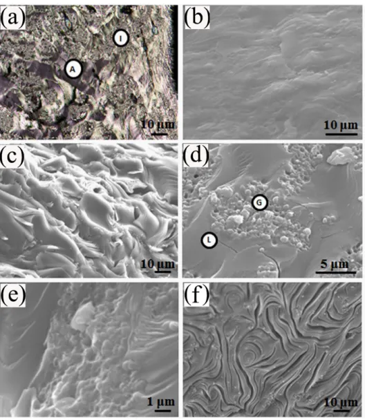
In order to investigate the structure of carbonized pure coal tar pitch, the polished, fractured, and etched sample surfaces were examined using optical microscopy and/or SEM (Figure 2 (a- f)).
The appearance of the carbonized pitch observed from Figure 2 (a) exhibits both optical anisotropic and granular textures , which are in agreement with results of carbonized pitch-coke presented in literature 14. The observed surface textures are similar to those found in metallurgical cokes 5. It was proposed by Hays et al. 5 that the texture of carbon materials can be lamellar, granular, and intermediate (mixture of lamellar and granular) which can be identified with SEM. The granular material could form due to the insertion of QI particles in anisotropic material, which interrupts the growth of anisotropic texture. Therefore, it can be said that the origin of the granular material is small anisotropic material (mosaics) associated with the QI agglomerates formed during pitch carbonization. It is not possible to observe clearly these textural components on the surface of polished pure carbonized pitch sample shown in 2 (b).
Therefore, the attempt was made for examining the fractured surface (see Figure 2 (c-d)). It was observed from the SEM results with a large magnification that the carbonized pitch in the current work contains only two different components, namely, lamellar (position L) and granular (position G) as can be seen in Figure 2 (d). The appearance of the granular component with primary QI particle accumulated in certain regions of carbonized pitch is clearly visible from the SEM image in Figure 2 (d), which shows the details of the fractured carbonized pitch surface.
Although the corresponding fractured surface shown in Figure 2 (d) does not show the detailed texture of lamellar component, the some characteristics can be seen for the two components. The percentage of different textural components can be determined from such micrograph. The percentage of the granular material is around 50 in this specific sample shown in Figure 2(d).
However, large number of tests has to be carried out to determine the percentage of each component in pitch. Generally, the QI contents of the pitches are 5-10% weight percent. Hence, the percentage of granular component in pure carbonized pitch found in this study is greater than the QI contents of pitch. This is in agreement with the results reported by Hays et al 5. They also showed that the portions of granular components present in two 9.7% primary QI-containing pitches exceeded their actual QI content after carbonization at 1000 °C. The implication seems to be that the granular components are not only composed of QI but also a small randomly- orientated granular matrix. The granular component increases with increasing QI but it is not equal to QI 5. However, the nature of the lamellar texture on the fractured surface cannot be clearly seen from this micrograph. Thus, the surface of pure carbonized pitch was etched with hot air and inspected with SEM to get more detailed information and compare with that of pitch in baked anode. The SEM micrograph illustrating the appearance of granular component after etching is shown in Figure 2 (e). The primary QI particles are flattened, but they can be seen
clearly from the micrograph in Figure 2. The lamellar nature on pure carbonized pitch surface can also be easily identified from the etched sample as shown in SEM image (Figure 2 (f)), which is complementary to the information obtained from fractured surface in Figure 2 (d). The observed lamellar crack patterns are the effect of etchant. The differences in topography of etched surfaces reflect a difference in the structural units of the carbonized pitch studied (see Figure 2 (e) and (f)).
3.2Structures of carbonized pitch in baked anodes
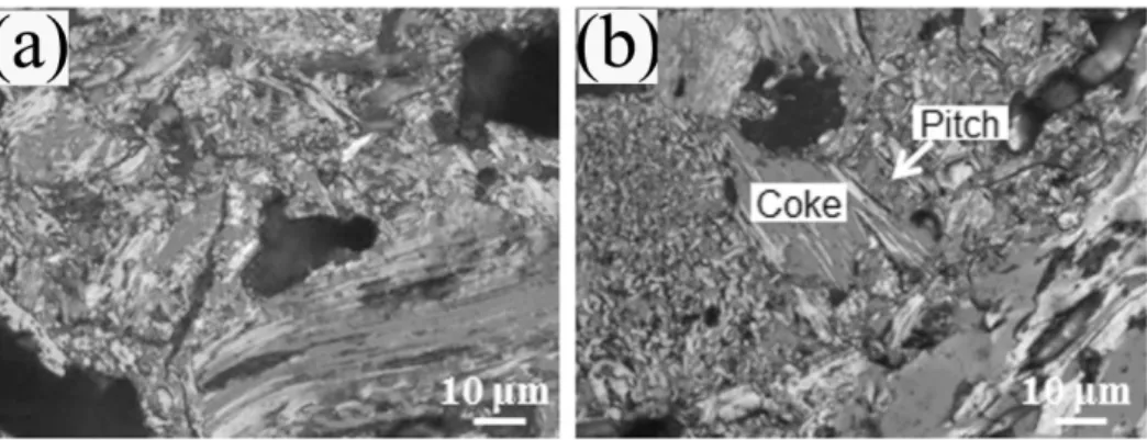
An optical microscope image with a magnification of 1000×, which shows a general view of a polished baked anode surface, is shown in Figure 3 (a). The presence of irregularly shaped inter- particle pores in anode is clearly evident in this figure. These pores are the result of volatile release from pitch during baking. With increasing temperature, the anisotropic component in pitch grows in size and ultimately coalesces to form carbonized pitch, which has similar hardness and composition with those of calcined petroleum coke. Therefore, it is not possible to see the boundaries of coke particles and carbonized pitch on the polished baked anode surface by optical microscopy without etching. Furthermore, because of the small depth of focus and two- dimensional view of this method, the details of the pores are not clearly distinguished.
According to literature, the etching by atomic oxygen induces a surface topography which reflects the structural order of the surface material of baked anode specimen 4. Etchants can attack the structural units differently. The differences in topography of the etched surfaces reflect the difference in the structural units of the carbon 5. In order to improve the quality of microscopy analysis, the polished anode samples were etched by hot air in the present study. As indicated by the arrow in Figure 3 (b), it is possible to identify the contours of coke particles in optical microscopy images of baked anode samples with this method. This means the
composition of baked anode can also be studied by means of various topographies created with the etchant. The effect of different etchants on carbon materials are not the same. The etchant used in this study attacks carbonized pitch easier than coke particle leaving the coke slightly raised on the etched surface. This difference can be attributed to the calcination of coke at high temperature (1200°C), which make coke more resistant to oxidation. The calcination temperature is higher than that of baking temperature (1100 °C), therefore, calcined coke and carbonized pitch have different properties such as crystalline length.
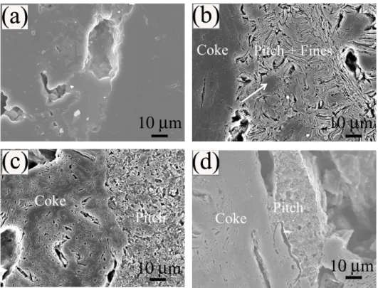
Due to the low magnification capacity of optical microscope, the texture of carbonized pitch is ambiguous in Figure 3 (b). Moreover, its small depth of focus requires highly even surface to obtain a clear image, which limits the utility of this method. The low magnification (1000×) SEM micrographs giving a general view of the polished and etched baked anode surfaces are presented in Figures 4. No notable information can be observed from these images of polished but non-etched baked anode surface in regard to the structure of carbonized pitch and coke.
Furthermore, it is difficult to differentiate the different carbons (coke and carbonized pitch) at this low magnification (see Figure 4 (a)).
SEM with its large depth of focus is well suited to observe topography of the etched surface and identify the interface between carbonized pitch and coke particles by their texture and a discontinuity between the two materials as shown in Figure 4(b-d). This is in agreement with the results given in literature 3. The carbonized pitch shows visible textural patterns while coke particle surface exhibits flat, less textured and darker appearance after etching. This result confirms those obtained from optical microscope analysis that coke is more resistant to oxidation compared to pitch even after baking. Figures 4 (b-d) demonstrate different textural patterns of carbonized pitch. Due to the micro-cracks created by etching, parallel arrangements of short
ridges and channels are visible in the carbonized pitch regions shown in Figure 4 (b).
Corresponding view of the same component visible in etched pure carbonized pitch surface is given in Figure 2 (e). Therefore, it can be said that the structure of carbonized pitch is lamellar and it is easily identifiable in the micrographs. The lamellar arrangements are broken by the fine coke particles present in pitch as shown with arrows in Figure 4 (b). It is worth mentioning that the lamellar texture in carbonized pitch and the principal component of the petroleum coke, which also exhibits a lamellar texture on the anode surface, are easily distinguished after etching using the method developed in this study. This is a significant improvement compared to previous methods 5. The textures of carbonized pitch in anode presented in Figures 4 (c) and (d) are different. Also, they differ from the lamellar texture shown in Figure 4 (b). However, the clear arrangement patterns of carbonized pitch in anode cannot be obtained from the micrographs in Figures (c) and (d) at this low magnification of 1000×.
Furthermore, it can be seen that the components of carbonized pitch in baked anode shown in Figure 4 (d) has less damages and defects than those in Figure 4 (b) and 4 (c) after etching. This indicates the different textural components react differently with etchant, which permits to understand the differences in oxidation of different carbonized pitch structures and coke in baked anode. In turn, this might provide possibility to control and optimize the textures of carbonized pitch components in anode.
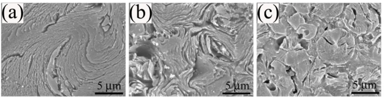
Figures 5 (a-c) show the higher magnification micrographs (5000×) illustrating the three different textural components of carbonized pitch in baked anode, corresponding to Figures 4 (b), (c) and (d), respectively. The nature of the lamellar component in the carbonized pitch in anode is clearly evident from the micrograph in Figure 5 (a). It exhibits smooth river patterns with arrangements of micro-cracks and carbon layers parallel to basal plane. The lamellar pattern
on etched surfaces of pitch in baked anode and pure carbonized pitch shown in Figure 2 (f) appear identical, which help determine the lamellar component of pitch in baked anode. The appearance of lamellar component in Figure 5 (a) is in agreement with those reported in literature 5. The growth of mesophase leads to the lamellar structure (anisotropic optical structure) in carbonized pitch. The presence of solids within the liquid phase of pitch influences significantly the enlargement pattern of the mesophase spheres 14. Presence of large mesophase particles of several µm diameter may increase the size of the regions of coalesced lamellar structure around the particle surface 14.
The granular component in Figure 5 (c) shows poor, random and distorted basal layer alignment with small pits and pores. The pit features appear to be due to the removal of QI particles during etching process. The granular carbonized pitch is composed of somewhat coalesced small spheres which have appearance similar to that of mesophase spheres. Slight lamellar realignment of molecules seems to take place after coalescence. Same basal carbon layers are arranged like rays or radius of circles, which is the textural pattern of single sphere before coalescing with others. The characteristics of granular component observed from these micrographs are in agreement with the description given in literature. Mainly, two forms of granular components were observed, first one has poor alignment of basal layer due to mesophase coalescence and the second one has random alignment of basal layer of compressed sphere units alone 3. No mesophase is present in the pitch-coke after calcination at high temperature. The form of sphere units present in the granular component (see Figure (c)) is similar to the spherical form of mesophase but they are not mesophase spheres. Another effect of pitch solids on the growth pattern of mesophase spheres is the severe hindrance of coalescence by the small particles, such as primary QI et carbon black particles, which stick on the surface of
spheres 14. It was reported that the presence of primary QI or carbon black particles enhance the granular component at the expense of the other components 5. These components differ markedly in appearance from the granular component of pure carbonized pitch shown in Figure 2 (e), which exhibits a grain-featured surface with visible QI particles after etching. The granular nature can be confirmed by its similarity to the granular component of carbonized pitch on etched baked anode as reported in literature 5.
The extent of basal layer alignment of intermediate component of carbonized pitch in baked anode shown in Figure 5 (b) appears to be between those of lamellar and granular components.
The texture is considerably coarser than that of granular component presented in Figure 5 (c), which is similar to the observation of Hays et al 5. Since there is no corresponding texture found in pure carbonized pitch, the intermediate textual form can be identified according to the characteristics reported in literature 3, 5, where the intermediate component is described as an elongated form of the granular component 5 and mixture of small distorted lamellae or elongated grains 3. When the alignment of lamellar molecules is restricted during mesophase coalescence, intermediate components formed are less ordered than lamellar components 3.
Although the low percentage of pitch and the interference of fine coke particles with pitch makes the quantitative determination of different carbonized pitch components of in commercial anodes, it is still possible to quantify these components by eliminating its interference with fine coke particles as reported in literature 5 or by carrying out the analysis with a large number of samples having larger surface. Further study is needed to correlate the anode properties with the proportion of various structural components present in carbonized pitch of anode.
3.3Interface between coke and carbonized pitch in baked anode
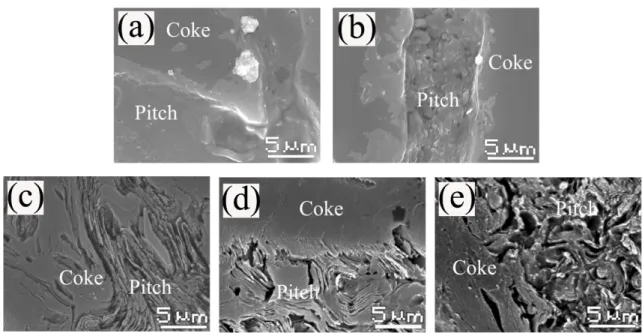
For pitch-bonded carbon anodes, the quality of the interface present between coke and pitch influences their strength properties 15. The interface between coke and pitch in baked anode can be identified by careful examination of samples using SEM at high magnification on polished surfaces (see Figure 6 (a-b)). No micro-crack formation was observed between coke and pitch, indicating good bonding between coke and pitch for the sample studied. Possible interaction zones at the interface of coke and carbonized pitch may indicate reaction. The possibility of the presence of reaction products has been deduced based on the difference in the lightness of the surface at the interface compared to that of the coke surface. The spherical particles of carbonized pitch in baked anodes can be visually identified in a SEM micrograph (Figure 6 (d)) even after polishing the sample surface but there is no indication of the presence of an lamellar structure (Figure 6 (a)). However, it is difficult to obtain detailed informaton about the interface from these micrographs. Hence, the etching of polished surface is necessary.
The etching method developped in this study can be used to obtain clear images of interfaces and interaction zones between coke and different textual components of carbonized pitch in baked anode (see Figure 6 (c-e)). Figure 6 (c) reveals that the orientation of lamellae of lamellar component in carbonized pitch is parallel to the coke surfaces. This is in agreement with the results of coke structure reported in the literature where the optical anisotropic materials in coke form lamellae parallel to insert surface 14. However, the orientation of carbon basal plane of granular component of pitch is not uniform. This randomness is due to its textural characteristics (see Figure 6 (e)). The isotropic structure in the granular component provides greater flexibility and diversity of chemical carbon chain along any plane for stronger bonding with coke particles, which can contribute to its higher fracture strength compared to those of the other components.
This is confirmed by the results reported in literature, which indicate that anodes containing more granular carbonized pitch have higher strength 3. The extensive crack development in lamellar component due to shrinkage of pitch during baking may reduce the mechanical properties of anodes. The surface energy of each textural component of coke is different and is considered to be important for its strength 15. Therefore, the strength of carbonized pitch bonded with coke may be also related to the surface energy of its components and their percentage.
4.Conclusions
In this study, the texture of carbonized pitch and its interface with coke in baked anode were investigated. A new etching method was developed. This method, which uses hot air as etching medium, gave precise information on the textural composition of carbonized pitch. It is possible to measure the portions of the various components present in carbonized pitch and correlate them to the other properties of relevant anode. However, this requires the analysis of a large number of samples. The method has been proven be safe, simple, and effective for etching baked commercial anode samples for SEM examination. A study on the relation between the etched textural patterns and the pitch properties as well as the pitch content in baked anode is in progress.
Acknowledgements
The technical and financial support of Aluminerie Alouette Inc. as well as the financial support of the National Science and Engineering Research Council of Canada (NSERC), Développement économique Sept-Îles, the University of Quebec at Chicoutimi (UQAC), and the Foundation of the University of Quebec at Chicoutimi (FUQAC) are greatly appreciated.
Reference
1. M.R.J. Tosta and E.M. Inzunza: Structural evaluation of coke of petroleum and coal tar pitch for the elaboration of anodes in the industry of the aluminum, in Light Metals 2008, (TMS Light Metals, City, 2008), pp. 887.
2. K. Neyrey, L. Edwards, J. Anthony Ross and F. Vogt: A tool for predicting anode performance of non-traditional calcined cokes, in 134th TMS Annual Meeting, edited by H. Kvande (TMS Light Metals, City, 2005), pp. 607.
3. D. Hays, J.W. Patrick and A. Walker: SEM characterization of cokes and carbons, in Fuel, City, 1983), pp. 1079.
4. D. Hays, J.W. Patrick and A. Walker: A scanning electron microscope study of fractured and etched metallurgical coke surfaces Fuel. 61(3), 232 (1982).
5. D. Hays, J.W. Patrick and A. Walker: SEM study of binder coke in electrode carbon Fuel. 62(8), 946 (1983).
6. H. Marsh, M. Forrest and L.A. Pacheco: Structure in metallurgical cokes and carbons as studied by etching with atomic oxygen and chromic acid Fuel. 60(5), 423 (1981).
7. A. Méndez, R. Santamaría, M. Granda, T. Morgan, A.A. Herod, R. Kandiyoti and R.
Menéndez: Influence of granular carbons on pitch properties Fuel. 82(10), 1241 (2003).
8. J.W. Patrick, M.J. Reynolds and F.H. Shaw: Development of optical anisotropy in vitrains during carbonization Fuel. 52(3), 198 (1973).
9. J.W. Patrick, F.H. Shaw and R.R. Willmers: Microscopic examination of polished coke surfaces etched by ion bombardment Fuel. 56(1), 81 (1977).
10. J.L. White: The formation of microstructure in graphitizable materials Progress in Solid State Chemistry. 9(C), 59 (1975).
11. S.S. Jones and E.F. Bart: Binder for the ideal anode carbon, (Publ by Minerals, Metals &
Materials Soc (TMS), City, 1990), pp. 611.
12. A.N. Adams, J.P. Mathews and H.H. Schobert: The use of image analysis for the optimization of pre-baked anode formulation, in 131st TMS Annual Meeting, edited by R. Peterson (Light Metals: Proceedings of Sessions, TMS Annual Meeting (Warrendale, Pennsylvania), City, 2002), pp. 547.
13. F.R. Barnet and M.K. Norr: Carbon fiber etching in an oxygen plasma Carbon. 11(4), 281 (1973).
14. H. Marsh: Carbonization and liquid-crystal (mesophase) development: Part 1. The significance of the mesophase during carbonization of coking coals Fuel. 52(3), 205 (1973).
15. D. Hays, J.W. Patrick and A. Walker: Application of SEM to studies of the strength of carbons Polymer - Plastics Technology and Engineering. 33(6), 713 (1994).
Table 1 Physical and chemical properties of petroleum coke and coal tar pitch used in the study
Properties Coal tar pitch Properties Calcined
Petroleum Coke Quinoline insoluble
(%m/m) 6.9 Bulk Density1 (g/cc) 0.87
Toluene insoluble
(%m/m) 29.1 Sp. Electrical
Resistance (µ ohm-m) 990
β Resin (%m/m) 22.2 CO2 Reactivity (%) 14.5
Density at 20 °C (g/ml) 1.320 Air Reactivity(% per
min) 0.23
Ash at 900 °C (%m/m) 0.12 Porosity of Coarse
Particles2 (%) 21.5 Coking value (%m/m) 59.1 Porosity of -125µm
Particles2 (%) 6.2
Softening point (°C) 119.6 Crystalline length(Å) 28.5 Dynamic viscosity 170
°C (MPa·s) 1390
Figure 1 SEM images of (a) primary QI particles and (b) mesophase spheres in pitch carbonized at 500 °C
Figure 2 Micrographs of pure carbonized pitch: (a) optical microscopy image of polished surface (A: anisotropic, I:isotropic texture), (b) SEM image of polished surface, (c) general views of fractured surface, (d) different textural components visible in fractured surface (G: granular, L:
lamellar), (e) granular texture and (f) lamellar texture on etched surface
Figure 3 Optical microscopy images of (a) polished non-etched baked anode and (b) etched baked anode
Figure 4 SEM images of (a) polished non-etched baked anode, and (b-d) etched baked anode showing (b) lamellar texture, (c) intermediate texture and (d) granular texture in carbonized pitch
Figure 5 SEM images showing different components of carbonized pitch on etched surface of anode: (a) lamellar; (b) intermediate; (c) granular
Figure 6 SEM images of interface between coke and carbonized pitch on polished surface (a-b) and on (c-e) etched surface in baked anode