AREAL DOSIMETRY AT RESEARCH CENTRES
Roland Lu¨scher*Paul Scherrer Institut, CH-5232 Villigen PSI, Switzerland *Corresponding author: [email protected]
Radiation protection regulations apply to research centres and nuclear facilities alike. Radiological dose resulting from their activities is strictly limited by law; therefore, it has to be monitored. As a supplement to the personal dosimetry systems (mainly for the work force classified as occupationally exposed), areal dosimetry is an efficient surveillance tool. Serving as an example, the concept of areal dosimetry applied at the Paul Scherrer Institut is presented.
INTRODUCTION
Accelerator centres and nuclear facilities are sub-mitted to the same regulations and legal guidelines on radiation protection. These include limitations on dose to the surrounding environment, as well as to the people living in the vicinity or to the work force on site. Swiss radiation protection regulation, as in most countries, is based on the recommendation from the International Commission on Radiation Protection(1). The annual limit on dose defined in the Radiological Protection Act(2) is 20 mSv for people occupationally exposed and 1 mSv for members of the public.
From these values, limitations to the ambient dose rates are extracted, based on parameters such as zone concepts and occupancy rates. These guidelines are regulated by the Swiss authorities (the Federal Office of Public Health and the Federal Nuclear Inspectorate (ENSI)).
The Paul Scherrer Institut (PSI) is the largest research centre for natural and engineering sciences in Switzerland. It operates several beam facilities, such as the world’s most intense proton beam accel-erator (1 MW) with a neutron spallation (SINQ) and muon source (SmS), a synchrotron light source (SLS) and a proton therapy centre. It also hosts nuclear facilities, such as a ‘Hot Laboratory’, two nuclear plants currently in decommissioning and a 0 W research nuclear plant (Proteus).
The above-mentioned limits and regulations impact naturally on all projects, old or new. It con-strains the design of new facilities on issues such as shielding material or thickness; it has consequences on the concept of supervised or controlled areas in and around a given facility; ventilation systems, access controls, emission monitoring, etc., have all to be adapted according to these legal boundaries. Of course, within this legal frame, PSI has a report-ing duty to the Swiss authorities. In theses regular reports, areal dosimetry plays an essential role. Beyond this latter point, the areal dosimetry has also proved to be a very useful tool for monitoring a
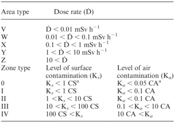
clean beam operation: it may help identifying locations of unwanted beam losses and, thus, bring-ing increased beam reliability and availability. DEFINITION OF RADIOLOGICAL ZONES Zones in Swiss nuclear power plants are defined according to an ENSI guideline(3). Zones are differ-entiated on the bases of dose rates (areal type V– Z) and/or on contamination risks (zone type 0 – IV). For details, see Table1. These definitions impact on allowed occupancy rates (and hence, access control) as well as on vestimentary constraints (such as overalls and breathing apparatus).
The specificities of accelerator facilities reside in the major difference in radiation risk between beam on and beam off. However, after connecting the access control system to the beam status (with poss-ible introduction of air purging time after beam oper-ation), it becomes clear that similar zone concepts can be applied. Thus, PSI uses the same definitions in both, its nuclear and accelerator facilities.
PASSIVE DOSIMETRY
The facility and area ambient dose equivalent H*(10) dosemetry is surveyed by a net of approximately 270 measuring positions. The gamma-dose is recorded by Al2O3 and 7LiF-based thermoluminescence dosemeters (TLDs). The neutron dose is integrated by fission track dosemeters:235U converters in mod-erator spheres (diameter: 23 cm) and232Th converters (with 0.1 % U content), respectively. The dosemeters are evaluated quarterly by the PSI dosimetry group and the recorded values reported to the authorities.
The choice of dosemeter is based on the expected dose and the expected energy spectrum. For gamma--dosimetry, Al2O3 is preferred in the non-classified areas, while the ‘standard’7LiF is used in the classi-fied zones. The former has a higher sensitivity to lower energies, while the latter has a broader
measurement range. Three TLDs are used at every measuring point for the purpose of cross-checks. All dosemeters are calibrated in H*(10), the ambient dose equivalent, at the PSI calibration facility. An uncertainty of 20 % is evaluated for a TLD at the reference energy of the 137Cs-line. The moderator sphere is used with235U converters in order to extend the energy range up to 20 MeV. Two devices are set at every measuring point. An uncertainty of 30 % is evaluated, based on a calibration with an Am/Be source. The main characteristics of the dosemeters used at PSI for areal dosimetry are summarised in Table2.
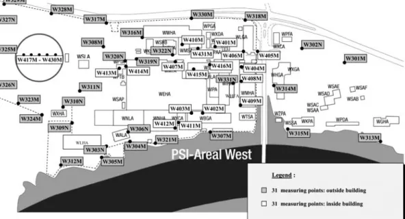
Measuring points are defined by the operational radiation protection group. Locations are classified into two categories: areal and facility dosimetric points (inside classified zones: laboratories, active workshops, etc.). The former consists of areas outside classified areas, such as offices, inactive workshops, roads, passages, etc. Special care is given to monitor the dose at the fence of the PSI area, as a mean to evaluate the direct radiation to the environment. As non-classified workers or visitors
can be expected at these points, an upper guideline value of 1 mSv y21shall not be exceeded. However, one differentiates between inside and respectively outside buildings, for instance near the fences, where occupancy rates can reasonably be assumed to be low (Figure 1). There, a guideline value of 5 mSv y21is tolerated(3).
Classified zones are subdivided into workplaces with permanent stay (where high occupancy rates can be expected) or temporary stay (with low occu-pancy rate) and off-limit areas. The latter are not accessible during operation without the explicit per-mission and under constant supervision of the oper-ational radiation protection. Occupancy rate is therefore the main parameter guiding the placement of measurement points (Figure 2). A guideline threshold of 80 mSv y21is valid for the first subcate-gory, based on the definition of a type ‘V’ zone(3). This value is extended to 200 mSv y21for low occu-pancy rate locations, following Appendix 2 of SR814.554 ordinance(4). As for off-limit areas, no limits are defined. Obviously, the guideline thresholds applying to the surroundings have to be observed, whereas effects such as sky-shine have to be taken into account.
The accumulated doses are evaluated quarterly using this net of passive dosimetry. This allows not only to fulfil the regular duty of reporting to the authorities, it also enables the study of long-term effects, such as an increase in beam intensity, the step-by-step commissioning of a newly built facility or the area surrounding an upgraded beam line instrument. PSI being a research centre, often chan-ging conditions call for a regular review of the network of measuring points, redefining and relocat-ing them.
ACTIVE DOSIMETRY
While long-term studies are best covered using passive dosimetry, flexibility to short-term changes (a specific experiment on a beam line, for instance, or temporary problems with beam components or increased beam losses) are better covered with active, online devices.
For this purpose, a network of measuring points is defined. Detectors are chosen according to the expected radiation field in first instance. Other important criteria are robustness and ease of oper-ation. The measurements are transferred via an RS485 bus to a central unit, where the data are recorded. The data are collected with the MEVIS (Centralised MEasurement VISualisation and data archiving)(5) software, which also enables the visual-isation of recorded values at any given time. This gives a tool for instant evaluation of any changes, as dose rate and beam current can be analysed Table 2. Characteristics of the dosemeter used for areal
dosimetry at PSI.
Type Measuring range Energy range
Al2O3 0.1 – 100 mSv 0.03 – 6 MeV
7
LiF 0.1 mSv – 5 Sv 0.03 – 6 MeV
235U conv.a 0.02 – 20 mSv Thermal to 20 MeV 232
Th conv.b 0.3 – 300 mSv Thermal to high energy a
With moderator sphere. bWith 0.1 % U content.
Table 1. Radiological zonetypes as defined in Swiss guidelines.
Area type Dose rate (D˙ )
V D˙ , 0.01 mSv h21
W 0.01 , D˙ , 0.1 mSv h21
X 0.1 , D˙ , 1 mSv h21
Y 1 , D˙ , 10 mSv h21
Z 10 , D˙
Zone type Level of surface Level of air
contamination (Ks) contamination (Ka) 0 Ks,1 CSa Ka,0.05 CAa I Ks,1 CS Ka,0.1 CA II 1 ,Ks,10 CS Ka,0.1 CA III 10 ,Ks,100 CS 0.1 ,Ka,10 CA IV 100 CS ,Ks 10 CA ,Ka
aCS, CA: Guideline values, isotope dependent, for surface, resp. air contamination as defined in Appendix 3 of SR 814.501 Radiological Protection Ordinance(2).
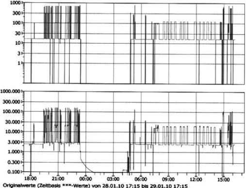
synchronously (Figure 3). These measurements are naturally backed up, as evidence for reporting purposes.
For neutron radiation fields, the LB6411 device from Berthold Technologies(6)is used as a standard. Depending on the necessary measuring range, Figure 1. Measuring points for areal dosimetry outside classified zones, for PSI-West.
gamma-monitoring is performed using either Geiger-Mu¨ller-counters or ionisation chambers. The devices used in the active areal dosimetry at PSI are summarised in Table3.
This system is therefore combining the robustness of an industry standard network with the appropri-ate detecting sensitivity. The network based on RS485 allows also flexibility: a mobile detector system can be hooked up to the network at any given connection box, which are set up throughout our facilities (Figure4). This gives the opportunity to easily concentrate a tighter surveillance around
new or upgraded beam lines or facilities during their commissioning, or experiments with higher radio-logical issues.
Table 3. Characteristics of the active devices used for areal dosimetry at PSI.
Type Measuring range Energy range
LB6360-H10(6)a 0.1 – 20 mSv h21 35 – 1300 keV LB6500-4(6)a 1E-4 to 1 mSv h21 55 – 2000 keV Centronic IG5(8)b 0.01 – 100 mSv h21 60 to 10E3 keV PTW 3l-Ch.(7)b ,10 Sv h21 80 – 1300 keV LB6411(6)c 0.1 – 100 mSv21h Thermal to 20 MeV aGeiger-Mu¨ller detectors. b Ionisation chambers. c Neutron monitor.
Figure 4. Active areal dosimetry: example of a
deployment of mobile devices. The position of each detector is optimised as to record the dose rate at the most strategic spots. The view is showing the roof of the Ring
cyclotron, part of the p-accelerator facility. Figure 3. Active areal dosimetry: example of synchronous analysis between beam current (top, in nA) and dose rate (bottom, in mSv h21) at the p-therapy accelerator facility. Note the exponential decrease of the latter at around 23:00 as
the beam is stopped: this is due to the decay of air activation products. R. LU¨ SCHER
The operation of a given facility is not directly coupled to its active areal dosimetry network. However, the following cases do generate a warning or alarm: the number of connected devices is below the agreed threshold (fixed in the operation instruc-tions); the activity at one location is above warning, respectively alarm threshold. If such an event occurs, the operation team is instructed to call the radiation protection and might have to stop the operation. The synchrotron facility SLS is, for instance, not operated if ,8 device units are connected. For ease of operation, the experimental areas are not classi-fied as zones; therefore, the limit is 1 mSv y21. This is monitored by the active areal dosimetry network, whereas the measured dose rate is integrated over a week and shall not exceed 20 mSv week21. Warning and alarm levels are adapted to zone types and radiation risks.
AIR ACTIVATION MONITORING
As can be seen from the definitions given earlier, possible contamination of the air does influence the classification of radiological zones. As a conse-quence, monitoring of the air activity is paramount. A network consisting of air probe lines has been set up, driving samples of airs to monitoring devices (Figure5). In this way, the air is assessed in terms of 3
H and bþactivities. The former is obtained with a
Tritium monitor LB671(6). For the latter, the air is directed into a gas chamber (of about 20 l), in which a standard NaI crystal detects the 511 keV annihilation line.
MANUAL DOSE RATE MAPPING
No network of passive or active devices can cover without any gap the surveillance of a given facility. For this purpose, nothing replaces mapping cam-paigns, operated by the radiation protection group using portable devices. A mapping is obtained by measuring systematically the dose rate around a shielded facility, while it is running in the least favourable conditions, i.e. the highest the beam intensity, the most demanding the beam operation. For instance, the Gantry from the proton-therapy centre is driven into a horizontal position for the purpose of the measurement campaign, as this direc-tion causes the most stringent shielding constraints.
The measuring points in any campaign are defined in high numbers (tens and hundreds) and high density. This has the purpose of identifying possible shielding weaknesses, which could be arbi-trarily small. Often, the results of the campaigns feed directly into defining the measuring points of both the active and the passive areal dosimetry network.
As ‘portable’ neutron device, the standard LB6411(6)is again used. For gammas, either a stan-dard Thermo/Bicron micro Sievert LE or a TOL/ F(6)is used, depending on the expected energy range.
CONCLUSION
For the purpose of its reporting duties to the Swiss authorities, PSI has set up a network of passive and active areal dosimetry. With these tools, the operational radiation protection can survey a safe operation of the large facilities. Particular care is given to review and update these networks regularly, responding to ever-changing conditions, typical of a research centre. Beyond these efforts, regular mapping campaigns are per-formed, particularly during commissioning of a new facility or beam line. These methods comp-lement each other, each fulfilling an important part in the radiation protection jigsaw.
REFERENCES
1. ICRP 103. The 2007 Recommendations of the
International Commission on Radiological Protection. ICRP Publication, Ann. ICRP 37, 2– 4 (2007). Swiss regulations are however still based on the earlier ICRP 60. Ann. ICRP 21, 1 –3 (1991). Available on: http:// www.icrp.org/publication.asp?id=ICRP%20Publication% 20103.
2. SR 814.50. Radiological Protection Act; SR 814.501 Radiological Protection Ordinance.
3. Guideline for the supervised areas in nuclear facilities and the Paul Scherrer Institut HSK-R-07 Federal Nuclear Safety Inspectorate, (1995).
4. SR 814.554. Ordinance on the Handling of unsealed radiological Sources.
5. UMAD. Umweltmesstechnik- und Datenverarbeitungs-gesellschaft GmbH Available on:http://www.umad.de. 6. Berthold Technologies GmbH & Co. Available on:
http://www. bertholdtech.com.
7. PTW Freiburg GmbH Available on:http://www.ptw.de. 8. Centronic Ltd Available on:http://www.centronic.co.uk. R. LU¨ SCHER