Design and Development of a Precision Packing Stage and Master Control System for an Automated Vial Packaging Machine
by
Diarny Oliveira Fernandes
Bachelor of Science in Mechanical Engineering University of Massachusetts, Dartmouth
Submitted to the Department of Mechanical Engineering in partial fulfillment of the requirements for the degree of
MASTER OF ENGINEERING IN ADVANCED MANUFACTURING AND DESIGN
at the
MASSACHUSETTS INSTITUTE OF TECHNOLOGY September 2019
©Diarny 0. Fernandes, MMXIX. All rights reserved.
The author hereby grants to the Massachusetts Institute of Technology permission to reproduce and to distribute publicly paper and electronic copies of this thesis document
in whole or in part in any medium now known or hereafter created.
Signature redacted
Author Certified _By AcceptdB MASSACHUST TI OF TECHNOL(SEP
19 2(
Signatu
Diamy Oliveira Fernandes /Dppartment of Mechanical Engineering
re redacted
August16,2019David E. Hardt Ralph E. and fJoi9*eQ Crss Professor of Mechanical Engineering
Signature redacted
Thesis SupervisorNSTITUTE Nicolas Hadjiconstantinou
NTT Gradua e Officer, Department of Mechanical Engineering 019
I Z
MITLibraries
77 Massachusetts Avenue
Cambridge, MA 02139 http://Iibraries.mit.edulask
DISCLAIMER NOTICE
Due to the condition of the original material, there are unavoidable flaws in this reproduction. We have made every effort possible to provide you with the best copy available.
Thank you.
The images contained in this document are of the best quality available.
Design and Development of a Precision Packing Stage and Master
Control System for an Automated Vial Packaging Machine
By
Diamy Oliveira Fernandes
Submitted to the Department of Mechanical Engineering on August 16, 2019 in partial fulfillment of the requirements for the degree of
Master of Engineering in Advanced Manufacturing and Design
Abstract
This thesis describes the design and development of the motion control system and precision machine elements utilized in a custom vial-packaging machine for use in the medical device industry. A unique rotary bowl feeder was developed for orienting and feeding the vials while a simple transfer line mechanism queues and loads them for packaging. For the mechanical alignment of certain motion elements elastic averaging was utilized to achieve satisfactory vial dispensing performance. A simple motion control system was developed using a Programmable Logic Controller with Human Machine Interface, as well as an ArduinoTM Leonardo with externally integrated stepper motor controllers. Finally, a machine vision system was integrated to provide
information on product packaging quality and machine performance metrics.
Thesis Supervisor: David E. Hardt
To my loving parents Jose and Vanda, who gave me life And to my genius brother Ednir, who gives me purpose
Acknowledgements
This thesis is the result of delicate work and expert guidance carried out by several individuals throughout its course. I would like to thank the following individuals for their contributions to both my personal growth as a graduate student at MIT, as well as my professional development as a mechanical engineer.
I would like to thank my teammates Efstratios Maskofidis, Steven Adam Ratner, Siyang Liu, and Paul Zhang. Their dedication to rigor, quality results, laughs, and peace made this a most pleasurable team experience. Their various skillsets and passions made this machine possible. In the rest of our M.Eng cohort, I would also like to thank Dehui Yu, Bowen Zeng, and Jessica Elizabeth Harsono for their support and friendship
throughout other courses during my time at MIT.
I would like to thank Professor Dave Hardt for his wisdom, patience and guidance. The M.Eng. thesis has demanding technical requirements and a strict timeframe -without him it would have been impossible to finish on time.
I extend many thanks to Professor Alexander Slocum for exposing me to the field of precision engineering. His graduate course was integral to my development as a machine designer.
I thank my lifelong friend and colleague Adam York, who came out of his way to help me with my thesis work at MIT. I know he will find himself here one day.
At our industry partner Waters Corporation, I would like to thank our advisors Jason Dion and Gabe Kelly, who granted us creative freedom and flexible site visits. Without their accommodations our design process surely would have suffered.
Finally, among those of us who started the MIT Hyperloop II team during our time in the M.Eng. program, I would like to thank once more the following individuals:
Siyang Liu, for his continuous humor, brotherly love, and extraordinary taste in Asian cuisine. Bowen Zeng, for inspiring me with his fantastic academic rigor, immeasurable respect for others, and grand dreams for the future. And finally Jessica Elizabeth Harsono, for keeping my spirits up with late-night adventures, inspiring me with her true love for others, and in the process becoming a genuine friend. I'll see you at APL!
Table of Contents
1. Introduction
a. Background and Motivation b. Objectives
c. Scope
d. Work Distribution
2. Automation
a. What is automation?
b. Why implement automated solutions?
c. Case study: modem motivations from industry
3. Problem Statement
a. Current Practice b. Design Parameters
i. Working Environment Restrictions 1. Material Selection
2. Energy Sources 3. Connectivity
ii. Part Handling Restrictions c. Existing Solutions
d. Proposed Solution Overview e. Individual Subsystems
i. Sorting and Orienting ii. Transfer Line
iii. Packaging iv. Motion Control
v. Inspection and Connectivity
4. Precision Packing Stage Design
a. Design Challenge b. Elastic Averaging
c. Material Selection d. Reliability Testing
5. Master Control System Design
a. Programmable Logic Controller (PLC) b. Human Machine Interface (HMI)
6. Results
7. Conclusions and Future Work
8. Appendix
a. Ladder logic diagrams
b. Arduino motion control code
Table of Figures
Chapter 1
Figure 1.1. A 350 pL QuanRecoveryTM vial (diameter 0.50 inch)
Figure 1.2. An advertisement for QuanRecoveryTM vials and plates with the inclusion of chemistry-themed socks [1]
Figure 1.3. A package containing 100 of the 350 pL vials with QuanRecovery Mcoating Figure 1.4: Functional prototype of the automated vial packaging machine
Figure 1.5: Annotated layout of the prototype machine
Chapter 2
Figure 2.1. A brief overview of a typical capacitor product line adapted from another manufacturer.
Figure 2.2. A typical automatic metalized film winding machine
Figure 2.3. The winding panel on the Hilton-90 manual winding machine Figure 2.4. The original logic control panel on the Hilton-90
Figure 2.5. The switchboard used by the operator to manually actuate certain machine elements and reset logic counters and timers during machine operation
Figure 2.6. Although versatile, this Allen Bradley CompactLogix TM PLC was rejected due to high acquisition costs
Figure 2.7. An IDEC H40RC PLC, the system chosen for the Hilton-90 control update Figure 2.8. An IDEC HMI available in several sizes and color options, the system chosen to replace the operator's switchboard system.
Figure 2.9. The updated Hilton-90 control board with the IDEC PLC and Panduit wiring management system
Chapter 3
Figure 3.1. A typical vibratory bowl feeder
Figure 3.2. The prototype rotary bowl feeder with outer shell attached
Figure 3.3. Sorting fins along the acrylic ring of the prototype rotary feeder (outer shell removed)
Figure 3.4. An illustration of the vial-sorting concept used in the rotary bowl feeder Figure 3.5. The proposed design for a production-level rotary bowl feeder. The diameter of the bowl will be 2 to 3 feet.
Figure 3.6. Layout of the vial transfer line system
Figure 3.7. Transfer line initial state (vials fed and ready to be loaded into rake via the queuing rollers)
Figure 3.8. Transfer line final state (vial being pushed into queuing roller stage in direction indicated by the purple arrow)
Figure 3.9. The rake actuation counting sensor, a 24VDC microswitch with rolling contact, wired normally open (NO)
Figure 3.10. The rake rest-position detector, a standard 24VDC microswitch wired normally open (NO)
Figure 3.11. The transfer line pusher rest-position detector, a 24VDC optical sensor Figure 3.12. Lead screw initial position sensor, a 5VDC limit switch wired normally open (NO) to the Arduino and normally closed (NC) to the PLC
Figure 3.13. Lead screw final position sensor, identical in specification and wiring to the sensor described in Figure 3.12
Figure 3.14. State machine diagram for packaging process
Figure 3.15. Breakdown of the prototype packaging stage developed for the machine Figure 3.16. Close-up view of the vial "rake" (pusher mechanism that prepares rows of 10 vials for packaging, outlined in red). The biasing mechanism is outlined in yellow with its direction of motion indicated in purple. The microswitch (indicated by the green arrow) senses every time the rake moves forward.
Figure 3.17. Machine vision algorithm output after processing vial image data. The black circles indicate vials that were successfully detected and counted by the algorithm.
Chapter 4
Figure 4.1. The preliminary concept sketches for the development of the vial rake Figure 4.2. Undesired (left) and desired (right) vial nesting structure
Figure 4.3. Result of Abbe error due to clearances in the linear actuator
Figure 4.4. The first failed flexure of the accelerated life test (23,039 actuations) with failure points indicated
Figure 4.5. Damage to the cam (upper) and the resulting residue (lower) from accelerated life testing (23,039 actuations)
Chapter 5
Figure 5.1. The simplest possible ladder logic statement Figure 5.2. Fundamental ladder logic symbols
Figure 5.3. Velleman TB6560 3A stepper motor controller available from Micro Center Figure 5.4. ArduinoTM Leornardo board used for directional control
Figure 5.5. The digital operating range for inputs on the IDEC PLC as specified by the manufacturer, adapted from the user manual
Figure 5.6. The relay board used to jump signals from both lead screw limit switches to the PLC input stage
Figure 5.8. The servomotor operational parameters set to the outer stage drive Figure 5.9. The Teknic
I/O
control cable pinout diagram for ClearPath© servomotors, adapted from the user manualFigure 5.10. The screen for testing various operations during the programming phase, including keeping count of actuations during flexure life testing (opens when "Testing Mode 1" is selected on the screen shown in Figure 5.13)
Figure 5.11. The screen for testing rake and biasing block operation during the programming phase, including keeping count of actuations (opens when "Testing Mode 2" is selected on the screen shown in Figure 5.13)
Figure 5.12. The first operation screen that opens when powering on the machine Figure 5.13. The screen that opens when either logo on the first screen is selected
Figure 5.14. This screen opens when "Run Mode" is selected on the screen in Figure 5.13
Chapter 7
Figure 7.1. The recommended IDEC HMI power supply (model PS5R-VD24) available from Marshallwolf Automation
Chapter 1
Introduction
L.a Background and Motivation
The demand for high performance low-cost alternatives to current engineering solutions is ever growing. The push for innovation has gone global, with incredible performance being achieved overseas in medical devices, farming and irrigation
systems, consumer products, and water desalination technologies. A more recent trend has been the desire for highly effective manufacturing systems that achieve high
repeatability with custom functionality at orders-of-magnitude lower cost than current systems. Packaging has long been an innovative and surprisingly complex branch of engineering, with focus on reducing lead times and tooling costs (which can be on the order of hundreds of thousands of dollars per packaging design). In the medical device industry, precision packing machines are necessary for quickly sorting and distributing geometrically small products in high volumes and therefore can be expensive. The motivation behind this thesis is to evaluate the possibility of developing a high performance and cost-effective packaging machine for an industry partner.
The analytical laboratory instrument manufacturing company Waters Corporation produces a comprehensive range of system solutions for the life sciences industry, providing auxiliary products that vary greatly in size. One of these products is
QuanRecoveryTM, which minimizes the effect of sample loss due to non-specific binding and ionic interactions through a proprietary surface coating. This coating is placed on the interior surface of 350 pL vials (see Figures 1.1 and 1.2) that are sold in packs of 100 (see Figure 1.3).
QuanRecovery
-Figure 1.2. An advertisement for QuanRecoveryTM vials and plates with the inclusion of chemistry-themed socks
The vials are typically packaged by hand at a rate of 100 vials about every 2 minutes. This method costs roughly 15 dollars per hour in labor, with a possible 0.5 dollars per package to save using automation. Due to the lack of mechanical precision in this method, it is common to have completed trays containing only 98 to 99 vials, leading to increased probability of damage during transit, particularly with the glass version of the vial. Due to this uncertainty, Waters must label the packages as having
"approximately 100" vials instead of "100" vials. They have expressed that they would like to remove the ambiguity with the current labeling.
The focus of this work is to describe the system designed and implemented to solve the packaging errors produced by human labor.
1.b
Objectives
The main project objective was to design an automated system capable of sorting and orienting 100 vials to reliably place them facing upwards and fill a 100-vial container. The key objectives were as follows:
-Receive a bulk load of vials and place them in a 10-by-10 matrix with all openings
facing upwards in a vial package (which will be referred to as a vial tray in this document)
-Fill a vial tray at least every 2 minutes or faster
-Minimize external particulate from accumulating within the vials
-Validate that 100 vials are placed into each package
-Keep development and production costs under $10,000
1.c Scope
The project scope was contained to developing and building a functional prototype (see Figure 1.4) that could be used to demonstrate the potential of the proposed automated machine. Once the prototype is complete and working, engineering drawings of each custom component are to be made along with an assembly and user manual. This way Waters can manufacture and operate future iterations of the machine as production
- ---
-Figure 1.4: Functional prototype of the automated vial packaging machine
Note that the yellow enclosure pictured in Figure 1.4 houses a large red emergency stop button. Disengaging this switch powers on the machine, therefore it serves as the
Cam
Actuator and Tray
Transfer Une DISCharge
Tray
Transport
1.d Work Distribution
The work involved in the Master of Engineering (M.Eng.) degree offered by the Mechanical Engineering Department at MIT differs from the Master of Science (S.M.). Rather than complete an individual project and thesis under a faculty advisor in any particular research group, the M.Eng. student joins a group of 3 to 4 students to provide a technical solution to an advanced design or manufacturing problem posed by an industry partner. This requires each student to develop their own unique contribution to a major project that combines all work done by the group. Each student's
contribution becomes the focus of his or individual thesis.
The technical solution developed by this M.Eng. group was split into five main subsystems as follows:
System 1. Rotary bowl feeder: sorts and orients the vials from a bulk disorganized state System 2. Vial transfer line: feeds the oriented vials into the packaging mechanism System 3. Precision packing stage: provides the necessary alignment and motion to reliably package 100 vials into the trays
System 4. Industry 4.0 integration hub: validates the packaged vials to ensure they are correctly placed using machine vision inspection and collects data on process output (namely the production rate of correctly packaged trays)
System 5. Mechatronics hub: utilizes a programmable logic controller (PLC), human machine interface (HMI), and ArduinoTM Leonardo board to control all motion axes of the machine and provide the operator with controls and immediate process feedback.
Although the group members shared the development of each subsystem design at various stages in the project, the specific task owners were assigned as follows: (System 1) Mr. Zhengyang Zhang, (System 2) Mr. Efstratios Moskofidis, (System 3) Mr. Steven Ratner, (System 4) Mr. Siyang Liu, and (System 5) the author Mr. Diarny Fernandes.
Chapter 2
Automation
2.a What is Automation?
In the long history of the manufacturing industries, the transition from hand-made to automated work has taken many forms and bloomed over the last quarter-century. Current buzzwords such as machine learning, data analytics, artificial intelligence and the Internet of Things (IoT) are redefining what popular belief would have once
suggested was the face of automation: robotics. Even over the last five years many questions have been raised on what truly defines automation and where it is going. In the workplace there are concerns over the ethics of replacing the human being with a machine. In the home there is concern over data collection and privacy, where both logical and physical machines are recording what we say, tracking products and
services we prefer, and tailoring the media we consume to our analyzed behaviors. It is easy to get lost in the many thousands of online articles warning of the impending danger of becoming a more mechanized civilization. However, from the perspective of an engineer, we must see the state of the art for what it is in order to extract from the hysteria the truly plausible implications of increasing automation.
For the purposes of this thesis, we will define automation as the use of a computer-guided mechatronic system to perform a physical task with little to no human intervention. The system may also collect data on its environment and respond to stimuli in that environment. However, it is not necessary for the system to do so in order to abide by this crude definition of automation. In this thesis we will focus specifically on what the human being relies on the machine to do and what types of mechanical intervention can be considered automation by this definition. We will explore the motivations for implementing physical automated systems on the factory floor and not software-only solutions such as data analytics and machine learning. These are for another technical discussion that is out of the scope of this particular thesis. For more detailed work on Industry 4.0 integration for this project, refer to the Mr. Siyang Liu's master of engineering thesism].
2.b Why Implement Automated Solutions?
Increasing throughput, reducing injury from repetitive motions or boredom, and making manufacturing less costly may immediately come to mind as the main
motivations for manufacturing industries to implement automation. With a computer-controlled machine the benefits are nearly immediate to understand: the company no longer has to pay an employee's hourly wage, insurance or other benefits just so he or she can continuously perform a single task or flow of tasks. Errors are reduced and the overall efficiency of the line is improved. The employee may then seek more engaging, personally fulfilling or challenging work. In the project pursued in this thesis, the machine is being developed with the intention of replacing most of the human labor required in a packaging process. The goal is for the number of operators to be reduced while the product produced by the process becomes free of human error. For the intent of this thesis project, the above stated goals of automation hold true.
However, in the widest scope of industry this definition makes some critical
assumptions that may not always hold. For instance, we assume that all companies have the skills and resources to purchase and install the automation equipment. In addition, we assume that employees do not enjoy their work and must want something more. These are harmful assumptions to make for the following reasons; many of the companies that would extract the most benefit from implementing automation cannot afford to, and many factory employees are perfectly content with their jobs (in many cases being more effective than any machine). The reality, as we will explore in a case study, is that cost-effective automation can be achieved by upgrading existing machines and processes with better control systems while improving workflows for employees rather than completely replacing them. Rather than executing human replacement, it is more practical for a company to supplement their workforce with better automated systems. This is at least true with small scale manufacturing businesses.
In this thesis we will give a complete treatment to these two styles of automation
implementation (replacement vs supplement), by exploring in the following case study the advantages of supplementing human labor with automation.
2.c Case Study: Modern Motivations from Industry
Capworks is a small company in New England that manufactures capacitors for many applications including lighting, motor controls, power factor correction, and mission-critical systems for the United States government and its contractors (see Figure 2.1 for examples of typical capacitor form factors). Capworks has a long history in New England and for several years it was a massive employer. In fact, many locals have friends or family that at one time worked at the Capworks. The company has been innovating in all aspects of its business practice in order to stay ahead of its
competition, including making new product development processes, recruiting young talent from local universities, and streamlining its manufacturing methods. As a result of its long history, Capworks has several critical but archaic machines on its
manufacturing floor and therefore they have found motivation to implement automation to keep them running.
Figure 2.1. A brief overview of a typical capacitor product line adapted from another manufacturer.
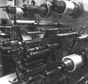
One specific process critical to the company is the winding of the capacitor. To be brief, almost all modern capacitors are composed of either metallized polymer film or film-foil wound onto a paper or plastic core. Most winding machines are automatic and foreign-made, costing several hundreds of thousands of dollars (one example is shown in Figure 2.2).
Figure 2.2. A typical automatic metalized film winding machine.
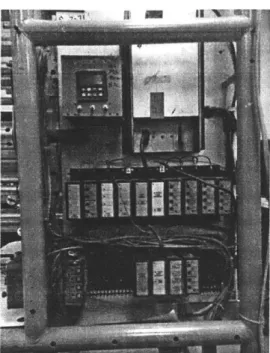
At Capworks there exist both automatic and manual winding machines, with many of the new ones available on the market being too expensive for the company to acquire, install and maintain at the time of writing. One critical product line relied on a manual winding machine (named the Hilton-90) that was beginning to suffer in its reliability. It took a long time to setup and required the operator to interact with a switchboard to communicate with the machine (see Figures 2.3-2.5). The original logic program for controlling the machine was inaccessible and could be lost at any moment. Capworks needed to upgrade this machine to a modem control system in order to streamline
operation and give the operator more feedback and setup options.
-I
Figure 2.4. The original logic control panel on the Hilton-90.
Figure 2.5. The switchboard used by the operator to manually actuate certain machine elements and reset logic counters and timers during machine operation.
A modem programmable logic controller (PLC) and integrated human-machine
interface (HI) were chosen to replace the outdated logic units on the Hilton-90. In the search for a new system, the Allen Bradley brand of PLC was considered but ultimately rejected due to hardware costs (in the thousands of dollars for hardware alone) and difficulty to implement (see Figure 2.6). Allen Bradley is the most widely recognized
brand of factory PLC systems, but here we find an example of the status quo being out of reach for a smaller company.
Figure 2.6. Although versatile, this Allen Bradley CompactLogixTm PLC was rejected
due to high acquisition costs.
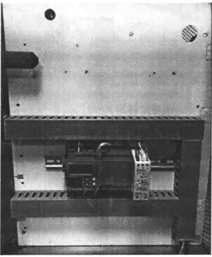
A $400 PLC and $700 HMI (both by IDEC) were chosen instead (see Figures 2.7-2.8). Provided in a starter kit at a discount with software included, this automation solution made the most financial sense to the manufacturing director at Capworks. An
engineering intern was tasked with programming the system and interacting with the operator to provide her with the necessary controls on the HMI. He was also entrusted with wiring the system to the machine.
Figure 2.7. An IDEC H40RC PLC, the system chosen for the Hilton-90 control update
Figure 2.8. An IDEC HMI available in several sizes and color options, the system chosen to replace the operator's switchboard system
This system upgrade proved to be incredibly beneficial to the company. Thanks to the programming software's ease of use, it was possible for the intern to do most of the machine programming at his desk, performing input/output testing without having to pull the actual machine offline until final installation. Having familiarity with Allen Bradley systems at his university, the intern also found IDEC's software much more intuitive. In addition, the operator gained the ability to set many more parameters on
the machine than before, with it activating several functions automatically (such as timer/counter resets and subroutines). The operator also enjoyed using the touch interface over the switchboard and felt valued that engineering time had been allotted
to improve her work experience (only a single operator used this machine, of which there are two). The machine program is also available and accessible by technicians should anything go wrong, effectively becoming part of the company's intellectual property. In addition, the new system proved much easier to wire than the original (see Figure 2.9), making it easier to troubleshoot if necessary. To the author's knowledge, the machine has not been offline since the control system upgrade.
Figure 2.9. The updated Hilton-90 control board with the IDEC PLC and Panduit wiring management system
This particular automation solution proved not only cost-effective but also easier to implement than the market-leading system. The operator's productivity was improved not because she was replaced with the system, but rather freed to do more work on the other machines she was responsible for. Here the automation supplements human labor. For its merits, the system described above was ultimately chosen for the project described in this thesis.
As previously stated, this case study serves to juxtapose the scenario presented by the Waters problem; it is an example where the operator is supplemented with automation rather than replaced (at least for the most part). The Waters problem differs because before involving this student team there was no machine to package vials; it was done
entirely by hand. Therefore the solution described in this thesis leans more heavily toward eliminating much of the operator's physical task and replacing it with setup and occasional monitoring of the automated system.
Chapter 3
Problem Statement
3.a Current Practice
Waters currently employs high school students (in groups of two) to manually orient and insert vials into the final packaging. The process is tedious and time-consuming, as vials must be handled and placed individually. It is also error-prone since it is difficult to achieve the 100-count vial arrangement when packaging by hand. There is no
machine or other mechanical aid to make the process easier or more accurate. There is also no visual inspection stage in the process to verify the exact number of vials
packaged per tray.
3.b Design Parameters
The company had its own requests for the design and performance of the machine. Ideally it should be easy to assemble, with as many parts being commercially available as possible. Production-ready drawings should be made available for any custom components. It should also be as close to table-top size as possible and have a
production rate of no less than what was achieved using human labor (one completed vial tray about every two minutes). The machine should first be capable of packaging plastic vials, but ideally it should handle both glass and plastic vials with little to no modification. Finally, a way of inspecting the trays for quality (specifically the number of vials packaged per tray) must be implemented.
Working Environment Restrictions
L Material Selection
In order to maintain the sterile conditions of the product, the machine must be composed of plastics that do not outgas or produce residue or particulates. Machine oils and greases must be avoided unless they are high enough in viscosity to prevent coagulation in critical contact areas.
II. Energy Sources
One significant challenge for the design of this system was the lack of access to shop air. Since the machine is located in a cleanroom
environment, compressed air cannot be used. Therefore, the only source of energy for mechanical actuation is standard 120VAC electricity at 60Hz.
III. Connectivity
The work area does not have wireless network access. Any data collection and communication must take place over Ethernet access.
Part Handling Restrictions
The most critical surface of the vial is the inner lining starting at the opening. No mechanical or chemical contact is allowed between this surface and any machine element used. Particulates must not collect inside the vial. Due to the small overall dimensions of the vial, it is not practical to implement any manipulator designed to handle individual units.
3.c Existing Solutions
The most challenging aspect of this machine design project is the sorting and orienting of the vials from a bulk chaotic state. Since the form factor is small as well as the
individual vial masses (2.3g for glass and 1.2g for plastic), a traditional vibratory bowl-feeding device was considered. However, further exploration revealed significant challenges with this approach that made it infeasible. For instance, most vibratory bowl feeders must be custom-made for the application and therefore can cost several
thousands of dollars. The space required to install the machine is also impractical since these feeders tend to require large bases (see Figure 3.1).
track
outlet
Figure 3.1. A typical vibratory bowl feeder
The base is used for mounting spring steel bars that serve for tuning the dynamic response of the bowl when electrically excited. Over time these work-harden and must be replaced, with factors such as the mounting torque, spring thickness, and spacer
thickness having the most impact on the speed of the bowl feeder. These machines also tend to be loud, which would not be suitable for operation in a small laboratory
environment.
For transferring and packaging vials, there are many more options. However, most machines are too large to fit the desired form factor and too expensive to justify
replacing human labor entirely. The vials handled by these machines also tended to be much larger than the QuanrecoveryTM vial. They also had caps installed, which make the vials easier to handle and transfer since there is a clear offset center of gravity with defined geometry. A preliminary patent search was executed to uncover any promising mechanical concepts for handling products similar in size to the QuanrecoveryTM vials. The search also served to shed light on existing overall concepts for this machine. The most promising concepts are reviewed in Mr. Efstratios Maskofidis's master of
engineering thesis[2].
3.d Proposed Solution Overview
The solution proposed in this thesis seeks to meet all of the goals set in section 3.b Design Parameters. Given the time restrictions, the machine was divided into the
minimal number of functional subsystems to fully demonstrate the concept of an automatic vial packaging system. The design chosen for the final production level machine is composed of a two-foot diameter rotary bowl feeder with an integrated vial transfer line and a precision packaging stage. For simplicity the system uses
components made using two-dimensional manufacturing techniques wherever possible (laser cutting, water jetting, etc.). The motion system and its required controls have also been kept to off-the-shelf components such as 24VDC stepper motors, Arduino boards and plug-and-play motor controllers. The master control system is based on a
commercially available and cost-effective PLC and HMI. Finally, an integrated visual inspection stage utilizes low-cost Raspberry Pi components to photograph and verify vial quantities at the completion of packaging.
3.e Individual Subsystems
Sorting and Orienting
A rotary bowl-feeding device was chosen over a vibratory one given the advantages it has over using vibration (as discussed in section 3.c Existing Solutions). The functional prototype (see Figure 3.2) utilizes a rotating foam center stage (placed at an angle) to agitate vials in a bulk chaotic state at the bottom of a reservoir. This component guides vials onto a sorting ring that rotates at a different RPM than the center stage. The ring is manufactured entirely from laser-cut acrylic and contains fins spaced precisely for isolating vials from each other (see Figure 3.3). A stationary cylindrical wall serves as the mounting point for sorting tools that separate vials as they travel with the sorting ring. Any vials facing the wrong direction are pushed out of place by the tools as they travel beneath them while correctly oriented vials are gradually pushed through the exit point to the transfer line. This sorting concept is explained in Figure 3.4 and the final proposed design for the system is presented in Figure 3.5. The entire process of design and development for this system can be reviewed in Mr. Zhengyang (Paul)
Center stage stepper Figure 3.2. The protc
a
Outer stage with sorting fins Figure 3.3. Sorting fins along
Outer shell of feeder
motor Teknic ClearPath* servomotor
type rotary bowl feeder with outer shell attached
Teknic Clearpathl*
servomotor
Center stage with Drive belt rotating foam cone
the acrylic ring of the prototype rotary feeder (outer shell removed)
BACKUP
RINGRININGQUILT
QULIFlIRINNER
WALL
SCALLOPS
OF BOWL
Figure 3.4. An illustration of the vial-sorting concept used in the rotary bowl feeder
Figure 3.5. The proposed design for a production-level rotary bowl feeder. The diameter of the bowl will be 2 to 3 feet.
TOOLING
Transfer Line
The transfer line was designed to receive vials from the rotary bowl feeder facing in a single direction and build a small buffer to the vial rake in the packaging stage (see Figure 3.6). It also serves to feed vials one-by-one into the rake in preparation for
packaging. A summary of the steps that achieve the desired transfer of the vials into the queuing rollers is included in Figures 3.7 through Figure 3.8. The design and
development of this critical stage is further reviewed in Mr. Efstratios Maskofidis's
master of engineering thesis 2 1.
f ) Vial queuing rollers
(with added twist to provide correct alignment of the vials with the rake)
Transfer line channel (receives vials from rotary bowl feeder) Vial in pre-transfer position
Spring-loaded pusher block (to transfer vials into rollers) Ball bearing to provide rolling contact between cam and pusher block
Cam stepper motor Figure 3.6. Layout of the vial transfer line system
Vials loaded from rotary bowl feeder
Pusher block in ready position
Spring relaxed
4 jjj'Vial in ready position
Figure 3.7. Transfer line initial state (vials fed and ready to be loaded into rake via the queuing rollers)
Vials loaded from rotary bowl feeder remainin position during push thanks to cutaway in pusher block
Pusher block in engaged position
Spring compressed
Vial (not visible) pushed into queuing rollers
Figure 3.8. Transfer line final state (vial being pushed into queuing roller stage in
Motion Control
The machine utilizes several motion axes to achieve reliable vial packaging. The following list describes all motors and actuators used on the prototype machine:
Vial rake - 24VDC stepper motor (operating a cam) Tray lead screw - 24VDC stepper motor (direct drive) Vial-biasing block - 120VAC linear solenoid
Transfer line feeder - 24VDC stepper motor (operating a cam)
Rotary bowl feeder (outer stage with sorting ring) - Teknic® ClearPathTM servomotor with integrated motor controller
Rotary bowl feeder (center stage with foam cone) - 24VDC stepper motor (note, this configuration is not for the final version of the rotary bowl feeder: the ClearPath servomotor will actuate both the outer and center stages at the same time)
Sensors are placed throughout the chassis to provide feedback on the machine's performance:
Transfer line entry: standard 24VDC standard 24VDC optical sensor (to be installed, see Chapter 7). This is for counting vials as they fall from the rotary bowl feeder into the transfer line channel.
Vial counter (integrated with rake): standard 24VDC optical sensor (to be installed, see Chapter 7). This is for providing feedback on the number of vials loaded into the rake for packaging.
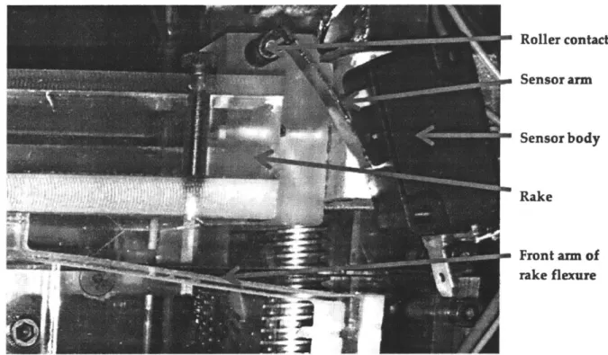
Rake actuation counter: 24VDC microswitch with roller contact, wired normally open (see Figure 3.9). This provides feedback on the row count during testing and automatic packaging operations.
Rake rest position detector: 24VDC microswitch, wired normally open (see Figure 3.10). This kills the rotation of the stepper motor when the rake returns to its initial position. Since the PLC does not directly control the position or velocity of any stepper motor on the machine, this sensor is necessary to prevent position creep.
Transfer line pusher rest position detector: standard 24VDC optical sensor (see Figure 3.11). This is integrated for the same reason stated for the rake rest position sensor. Lead screw initial and final positions: two 5VDC microswitches, wired normally open directly to the inputs on the Arduino Leonardo board, and simultaneously through
The motion is controlled using a PLC and HMI by IDEC. The state machine diagram is provided in Figure 3.14 to describe the logical actions for the packaging process.
More information on the development of the control system is presented in Chapter 5 of this thesis. a Roller contact - Sensor arm " Sensor body --Rake rke flexr
Figure 3.9. The rake actuation counting sensor, a 24VDC microswitch with rolling contact, wired normally open (NO)
Rear arm of rake flexure Rest-position detector,lever in contact with rake flexure Rest-position detector, sensorbody
Figure 3.10. The rake rest-position detector, a standard 24VDC microswitch wired normally open (NO)
Transfer line
stepper
Cam
Rest-position detector
Figure 3.11. The transfer line pusher rest-position detector, a 24VDC optical sensor
d
Circuit with integrated LED (not shown, opposite side)
Sensor body (not entirely visible, mounted on opposite side of circuit board)
Sensorarm
Figure 3.12. Lead screw initial position sensor, a 5VDC limit switch wired normally open (NO) to the Arduino and normally closed (NC) to the PLC
Sensor body (mounted on opposite side of circuit board)
Sensor button (arm removed)
Circuit with
integrated LED (not shown, opposite side)
Figure 3.13. Lead screw final position sensor, with identical specification and wiring to the sensor described in Figure 3.12
Initialize lead screw position
Initialize vial rake cam position
IReset
all countersI
=
I
Check for vials If transfer line is empty -1Start rotary feederIf transfer line is full
IStop
rotary feederI
=
ICheck
vials in rake - If rake has 10 vials if rake has c10 vialsFeed ralke from transfer line
If row count <10
I
IStop
feeding rake Reset rake countDispense vials
Check row count
If row count=10
I
Add 1 to row count
I
4 If row count odd If row count even
Engage bias block Disenge bias block
I
Tray inspection
If vials in tray=100 If vials in tray not 100
Eject trayto good pile Eject tray to reject pile
-4
I
I
I
Packaging
The packaging stage utilizes the basic principle of elastic averaging to achieve repeatable motion. This stage of the machine receives ten vials at a time from the transfer line and dispenses them row-by-row into the final packaging tray (this is done ten times to achieve the final tray of 100 vials). A biasing block shifts every other row of vials by roughly one diameter so that the vials are nested in the most space-efficient configuration. This is how errors are eliminated and 100 vials can be consistently packaged into each tray. The flexure used for actuating the vial collector (or "rake" as named in this thesis, see Figures 3.15 and 3.16) serves the purpose of eliminating any misalignment of the vial rows due to direct mechanical drive. As a result, the vial rake remains parallel with the tray during vial dispensing, resulting in consistent
performance. The flexure is actuated using a cam drive attached to a stepper motor. For more detailed information on the design and development of this stage, please refer to chapter 4 of this thesis, as well as chapters 4-5 of Mr. Steven Ratner's master of
engineering thesis[4]. Tray queuing slider Rake Rake Flexure Rake cam steppermotor
Lead screw for tray shifting
Tray exit ramp
Figure 3.15. Breakdown of the prototype packaging stage developed for the machine
Figure 3.16. Close-up view of the vial "rake" (pusher mechanism that prepares rows of 10 vials for packaging, outlined in red). The biasing mechanism is outlined in yellow
with its direction of motion indicated in purple. The microswitch (indicated by the green arrow) senses every time the rake moves forward.
Inspection and Connectivity
The final stage of the packaging process is automated inspection and data transfer. The system is developed to confirm that the correct number of vials has been placed in a tray. In addition, the process owner desires to keep track of the manufacturing data produced by the machine since the process happens at an offsite location. Therefore a data delivery system is also developed to post operational data in a server so that the process owner can monitor the machine performance in real time.
A Raspberry Pi 3 Model B+ and a Raspberry Pi NoIR Camera (with infrared capability) module enable the automated inspection system to collect data. As a completed tray of vials exits the packaging stage, it enters a black box with the camera installed on the ceiling. The black box is selected in order to create a controlled lighting environment for the camera to deliver consistent photographs. Both white LEDs and infrared LEDs are selected to provide adequate lighting inside the black box so that the camera can
- __________________________ ________ __________- ___
OpenCV to run feature recognition algorithms. Figure 3.17 presents an example of the algorithm identifying vials correctly oriented in a tray.
Figure 3.17. Machine vision algorithm output after processing vial image data. The black circles indicate vials that were successfully detected and counted by the
algorithm.
Once the image recognition algorithm finishes running, the output data is stored in the SD card with Raspberry Pi, which keeps track of the machine uptime and total number of properly packed trays that have been produced. Along with other crucial operational data such as machine throughput rate and machine uptime, these data will be sent through Ethernet to a company server for storage and inspection.
For a detailed view of the automated inspection and connectivity of the machine, please refer to Mr. Siyang Liu's master of engineering thesisM.
Chapter 4
Precision Packing Stage Design
4.a Design Challenge
Since the form factors of both the glass and plastic vials are similar (differing mostly by mass), their geometries can be handled in similar ways. The challenge with handling the vial comes with the location of its center of gravity, which through experimentation appears to lie near the center of each vial. This is contrary to our expectation that the center will be biased toward the feature that takes the most material to form (such as the neck of the vial or the body, depending on the wall thickness and thread size). Since the height of the body of each vial is small, there is a similar amount of material between these two features, so no obvious imbalance can be used to an advantage.
However, it was discovered that tilting any mechanism designed for dispensing the vial into a tray would assist in maintaining its stability and alignment. The critical insight when packaging vials by hand is that it is very difficult to nest them such that 100 fit into the tray. However, by using a precision mechanism to control the amount of vials dispensed (ten) and the number of dispense operations per tray (also ten in order to achieve 100), all that needs to be done is control the vials as they fall into the tray.
A preliminary concept for the mechanism that became known as the vial rake is presented in Figure 4.1. For clarification, a description of each stage (1-4) is also
presented below. The sketches in the figure are all from a side view; therefore the reader must envision ten vials going into the page.
Stage 1. Initial position: the rake supports a row of ten vials over a plate. A linear actuator is attached and retracted. The tray sits below the plate with one of its walls just about flush with the end of the plate.
Stage 2. Actuator shift: the linear actuator extends to release vials into the tray, they fall and due to the angle of the entire mechanism, remain supported by a wall such that they do not scramble upon making contact with the tray.
Stage 3. Actuator return, tray shift: while the actuator returns to the initial position, the tray shifts down (in the same direction as the actuator, indicated by the arrow in the figure) by roughly one vial diameter. This is to prepare space for the next row of ten vials, which is loaded after both of these motions cease. Not shown in the figure is the existence of the biasing mechanism, which slightly shifts every other entire row of vials so that they nest properly (refer to Figure 4.2 for clarification on the nesting structure). Stage 4. Repeat for packing: stages 1, 2, and 3 are repeated until ten rows of ten vials each have been dispensed into the tray. The filled tray is then ejected.
Figure 4.2. Undesired (left) and desired (right) vial nesting structure
4.b Elastic Averaging
Elastic averaging is one of the standard methods of eliminating error motions in machine elements. By using compliant mechanisms, the errors cancel each other and parasitic motions can be significantly reduced or eliminated. It was observed that due to the orientation of the rake and the desired mounting point for an actuator, Abbe error (motion error due to an angular clearance exaggerated over long distance) had the potential to become problematic. For instance, if there is a small clearance between the push rod and the housing of the linear actuator (most likely to be a standard 120VAC push-pull solenoid) and the rod were to be mounted to the center of the rake, the rake would then have exaggerated error motion at its left and right ends. Refer to Figure 4.3 below.
4 " ...
The displacement error p can be calculated by the following geometric relation:
L
p = -sin02
Where L represents the length of the rake and the angle 0 increases with higher clearance length 6. In addition, as the length of the rod increases with respect to the length of the housing, this will also increase the displacement error.
In order to avoid jamming the vials during the dispensing operation, direct mechanical contact using a traditional linear actuator was abandoned. Instead, a plastic flexure based on a four-bar linkage was chosen to provide linear alignment of the rake. A cam operated by a stepper motor was also used in lieu of a standard solenoid actuator due to highly undesirable noise, shock, and vibration observed with test units. More detail on the design of the cam and flexure is covered in Mr. Steven Ratner's master of engineering thesis 4 .
In addition, a lead screw shifts the tray beneath the plate under the rake. In order to reduce errors in this stage's motion, a helical coupling was used between the stepper motor and the lead screw, while two points of sliding contact where established such that the distance between them is at least 3 to 5 times the width of the bearing surface. This was done in order to reduce the probability of jamming, which is an adaptation of St. Venant's principle as taught by Professor Alexander Slocum in his precision
engineering course at the Massachusetts Institute of Technology.
4.c Material Selection
Materials were chosen for the flexure based on desired geometry, reliability, and manufacturability. The flexure is made from half-inch thick polycarbonate for its viscoelastic properties, and was cut on a water jet for convenience (it is also against standard practice laser-cut polycarbonate since this would produce dangerous gases). Acrylic was chosen for most of the other elements of the packing stage for rapid
prototyping purposes only. It is recommended that standard engineering metals such as aluminum 6061-T6 be used for most of the rest of the structure of the packing stage in order to increase its stiffness. This is also covered in Mr. Steven Ratner's master of
4.e Reliability Testing
A preliminary mechanical evaluation was required to help characterize the performance of the flexure over many cycles. Since it is difficult to simulate exact working
conditions, a crude accelerated life test was designed. With the intention of running twenty-four hours, the test was intended to provide more drastic conditions than would be expected in the field. The effects of continuous actuation on the long-term elasticity of the flexure material were not explored prior to this study. The goals were to establish a basic relationship between the thickness of the flexure linkages and the performance of the flexure. The ladder logic for the life test can be located in the appendix (Chapter 8 section 8.a). The following preliminary calculations were made to give direction toward selecting the reliability test conditions:
8 working hours 3600 sec 5 work days 52 weeks sec
* * *= 7,488,000
work day working hour week year year
Estimating 1 actuation per 10 seconds will result in 748,000 actuations per year.
Therefore for the following life cycle frequencies:
1 cycle per second will require 208 hours of continuous testing (8.66 days) 2 cycles per second will require 104 hours of continuous testing (4.33 days) 3 cycles per second will require 69 hours of continuous testing (2.89 days)
First experiments proved to be noisy and not ideal for all-day running in a shared laboratory space, therefore these estimates were changed in favor of running a shorter test twenty-four hours a day over a weekend (when the space would be least occupied).
Instead, estimating 1 actuation per 15 seconds results in 499,200 actuations per year.
Therefore for the following life cycle frequencies:
1 cycle per second will require 139 hours of continuous testing (5.78 days) 2 cycles per second will require 69 hours of continuous testing (2.89 days) 3 cycles per second will require 23 hours of continuous testing (less than 1 day)
The actual measured cycles per second were 1.25, bringing the life test to simulate only 108,000 cycles per day (which is only 0.14 of a working year equivalent per twenty-four hour test day).
The first flexure tested (see figure 4.4) had arms of 0.065 inch in thickness. The flexure survived only 23,039 actuations, which at 1.25 cycles per second equates to requiring replacement every 12 days (assuming constant use twenty-four hours per day, which is not realistic). The wear observed on the cam mechanism (see Figure 4.5) is the result of
the destruction of clear tape that was applied to the contact surface on the flexure (in order to reduce friction between the flexure and cam).
The second flexure tested had linkage arms of 0.050 inch thickness and lasted 39,718 cycles (equivalent to about 21 days).
Figure 4.4. The first failed flexure of the accelerated life test (23,039 actuations) with failure points indicated
Figure 4.5. Damage to the cam (upper) and the resulting residue (lower) from accelerated life testing (23,039 actuations)
It is suspected that lowering the spring constant of the flexure by changing the
geometry has beneficial effects on the reliability of the rake mechanism since less force is required to actuate it. This results in less wear at the cam-flexure interface and less wear on the motor since it then requires less torque to spin the cam.
With a 23% reduction in linkage thickness there was a 72% increase in cycle life. Although the correlation is crude, it is categorically significant. In order to further characterize the relationship between the linkage arm thickness and cycle performance (as well as the influence of other factors such as continuous vs. intermittent testing and other geometric features), a design of experiments will be required.
During testing it was observed that significant vibrations occur due to the nature of the stepper motor's rotation. The motor's natural response to pulse-width modulation (PWM) from the control system results in visible vibration that is transferred directly to the flexure due to the sliding contact point with the cam. It is possible that this increases the stresses on the flexure and causes premature failure. Design changes must be made to the interface between the cam and the flexure in order to reduce this possibility.
Chapter 5
Master Control System Design
5.a Programmable Logic Controller (PLC)
As previously stated, the control system for the machine uses an IDEC platform, which includes an HMI and a PLC. The system architecture is simple to integrate and easy to program. The PLC has 24 digital input channels operating between 0 and 28.8 VDC and 16 output channels with any option for voltage per output channel. For instance, if the operator wishes to activate a 120VAC solenoid, they need only bring 120VAC line voltage to the output common and connect the solenoid to the output channel, closing the circuit to activate the output using the PLC. To activate any output, the PLC must be programmed with a function to receive an input. The simplest possible logical
statement that can be executed is a single input (sometimes called a relay) and single output (sometimes called a coil, see Figure 5.1). Traditionally, this type of programming is referred to as ladder logic, with the one shown in Figure 5.1 being called a rung, and the lines that join elements being known as ladder lines.
Input (normally open) Output
H
-Figure 5.1. The simplest possible ladder logic statement
In this configuration, the input stage is in the normally open (NO) state, where the output activates only when the input is logically true (such as when closing an open circuit with a switch to turn on a light). A table of common ladder logic symbols is shown in Figure 5.2. Multiple inputs may exist on a single line, however only a single output can exist per line. This is not to say however, that multiple outputs cannot be activated at the same time with the same instruction, doing so only requires adding branches between rungs or using an output instruction from a previous rung as an input instruction on several rungs that possess differing outputs.
Normally Open Nornay Closed
(NO) (NC)
coil
Box
Figure 5.2. Fundamental ladder logic symbols
The IDEC PLC has its own unique features, which can be explored in depth by reading the user manual and ladder logic programming manual. The software used for
programming this system is IDEC's Automation Organizer WindLDR. For basics and to save time, we will review only the fundamental elements required to understand its function in the vial-packaging machine.
Inputs have programming addresses in the format of "I" followed by a number (i.e., O, I1, 12, etc.). These correspond to where on the PLC's input channel they are wired. Outputs follow a similar address format, differing only by a "Q" (QO,
Q1,
etc.).Internal relays are virtual tools that represent intermediate steps between inputs and outputs. They are often used to mark the state or status of a particular logical statement. For instance, one may choose to activate an internal relay rather than a physical output simply to flag in the code that a logical condition has been met (thus saving space on the output terminal since no physical output action is needed). These relays may also serve similarly as inputs. For instance, instead of wiring a microswitch to an input to change a logical subroutine, one simply programs a virtual button on a display to activate an internal relay on the PLC. For this reason, there are hundreds of open internal relay addresses available to the programmer, and these are denoted with an "M" followed by a number.
hundredths or thousandths) and timing action (off-delay vs. on-delay). Similarly, there are different types of counters based on the action desired (count-up, count-down, adding, etc.). Attaching inputs to their reset channels resets counters, while timers are only reset when their input conditions reset first.
Label call instructions are used to activate subroutines within other parts of the program. This is most useful for creating multiple phases of a machine's operation using the same physical inputs and outputs. Without these instructions it is nearly impossible to create a sequential set of actions using ladder logic since whenever an input is activated, all its instances in the program are activated.
Although the PLC does have the capability to control a motor by outputting a PWM signal, the process is much simpler to achieve using a low-cost external motor
controller. For this purpose, a commercially available stepper controller was chosen (see Figure 5.3). An Arduino Leonardo (Figure 5.4) was used to provide directional control logic for any motors that required reversal (particularly to control the lead screw for tray shifting).
Figure 5.3. Velleman TB6560 3A stepper motor controller available from Micro Center
The speed of the motor is set using the switches visible on the board in Figure 5.3. Directional control is achieved using microswitches attached to an Arduino with specialized logic (see Figure 5.4 and Chapter 8 section 8.b for control logic). These switches act to sense the limits of the tray shift mechanism and either stop or switch direction of the lead screw. The PLC only actuates 24VDC output from the motor controller to the stepper motor when needed. The logic on the Arduino is never communicated to the PLC; since they use different languages, they must operate independently. Therefore in order to monitor the status of the lead screw rotation direction, the switch input signals must be split between the PLC and the Arduino. The switches operate on 5VDC from the Arduino, however the PLC can only detect between 15-28.8VDC on the input terminal (see Figure 5.5). Therefore, an external relay board (see Figure 5.6) is utilized between them. This allows the low voltage switch to actuate the higher voltage needed for the PLC to read the signal without damaging the
Arduino. The LEDs are inherently wired normally closed (NC) on the relay board, representing an open circuit when powered on. Therefore whenever either limit switch is engaged, the LED is deactivated. In contrast, the limit switches each have their own inherent LED that is wired NO, powering on only when engaged (see Figure 5.7).
Input
Voltage (V DC)
28.8I
24
15
5.
LI_
JArea
I
K-L
Input Current
(mA)
0.9
2.7
4.4
5.3
Figure 5.5. The digital operating range for inputs on the IDEC PLC as specified by the manufacturer, adapted from the user manual
ON Area
Low voltage side of circuit (5VDC from limit switches)
Relay units
High voltage side of circuit (24VDC from PLC power supply terminal) LEDs indicate open circuit (wired normally dosed, NC)
Figure 5.6. The relay board used to jump signals from both lead screw limit switches to the PLC input stage
The motor used for activating the outer stage of the rotary bowl feeder (see Figure 3.3) is a ClearPath© servo manufactured by Teknic. This motor has an integrated controller with plug-and-play software (ClearPath MSP) that allows the user to specify several operational parameters such as acceleration and deceleration, torque limits, rotational direction, velocity, and more. The motor also comes with a control cable that can be connected to a PLC output terminal to control up to four operational conditions preset by the programmer. For instance, for the vial-packaging machine we have specified two operational velocities (30 RPM and 45 RPM) in the same direction. These values were entered into ClearPath MSP as shown in Figure 5.8 and saved directly to the motor.
File Edit Mode Setup Advanced Help Ra
Velocity Selection Setup(RPM)
1) Aoff Boft 2) AU Boff 3) Aof B
0.00
0 00 1-30.00 Accel 1P0IS} RDecel =Accel mp to Selected Velocitys 4) AN B [45.00 Torque Limit OVRSuDecel Profile Conversion RAS" OFF
Setup_
inputs and Enable Input A Input B Commanded Velocity Servo On Output Commands Onoff V-sel A V-sel8 (RPM)
0.00 Servo Of
r Override -0.
Inputs
RMS Max: 48% Velocity (RPM) Exceptions
isabled 11%
o
This motor still contains default tuning values. Once your mechanics are attached, be sure to run Auto-tuning (in Setup renu).
Figure 5.8. The servomotor operational parameters set to the outer stage drive