Data Flow Models
for
Fault-Tolerant Computation
Gregory M.)Papadopoulos
B.A., University of ~ a ~ o r n i a , San Diego (1979) Submitted in partial fulfillment
of the requirements for the degree of
Master of Science
at theMassachusetts Institute of
Technology
June 1983 O Gregory M, Papadopoulos A / I
...-.
. . .
Signaturle of Author. . .
May 13,1983. . .
Certified by..
. .-
. . . .
.-.
w.. . .
Arvind, Associate Professor of Electrical Engineering
.
.
. . .
Certified by
. . .
.
(7 *-P'-*tr
. V . ..-.
. - . - . V . .
Larry-, Cmles awk Draper Laboratory
Accepted by
. . .
.
,
,
v
w-w-H..-ev.
. . .
A -\ @
*Acknowledgments
I thank Professor Arvind for his encouragement, confidence, and valuable contributions in
this work; Dr. Larry Brock for his unending support and confidence, in me and in my research; Dr. Basil Smith and Dr. John Deyst for the many valuable discussions and suggestions that has kept the research topical; Most importantly, my wife, Elizabeth, for her unfailing support, encouragement, and unmatched editorial skills.
Special mention is due to the Charles Stark Draper Laboratory for providing the facilities, and support for this research. This work was performed under IR&D Project No. 18701. Publication of this thesis does not constitute approval by Draper Laboratory of the findings or conclusions contained herein.
I hereby assign my copyright of this thesis to the Charles Stark Draper Laboratory, Inc.,
Cambridge, Massachusetts.
Permission is hereby granted by the Charles Stark Draper Laboratory, Inc. to the Massachusetts Institute of Technology to reproduce any or all of this thesis.
Data Flow
Models
for
Fault-Tolerant
Computation
by Gregory M. Papadopoulos Submitted to theDepartment of Electrical Engineering and Computer Science on May 13, 1983 in partial fulfillment of the requirements
for the Degree of Master of Science
Abstract
Data flow concepts are used to generate a unified hardware/software model of dispersed physical systems which are prone to faults. Fault propagation is restricted to occur only through the data exchange mechanisms between independent modules. A powerful fault model, token fragments, is used to express vagaries of such exchanges in the presence of faults. The need for source congruence among inputs to similar fault-free modules is established, and procedures are developed for both the construction and analysis of
congruence schemata in the presence of faults. The need for nondeterminate operators is
justified for real-time systems, and a method for maintaining source congruence is presented for such systems. Events are defined as the receipt of tokens by operators, and a technique for minimizing the time-skew between similar events, synchronization, is developed. Applications are explored and bounds are given for the minimum number of independent hardware modules that are required for correct system operation in the presence of a specified number of faults.
Table of Contents
Chapter One: Introduction
1.1 The Data Flow Approach
1.2 Problem Development
Chapter Two: Simplex and Redundant Programs
2.1 Source Language, L0
2.1.1 Syntax 2.1.2 Semantics
2.1.3 Input Robustness of Lo Programs
2.2 A Language to Express Redundancy: Ro
2.2.1 Ro Program Graphs
2.2.2 Lo Program Instances
2.2.3 Voters
2.2.4 Restoring Buffers
2.2.5 External Inputs and Redundant Outputs
2.3 Abstracting the Implementation: Fault Models, Fault Sets, and Unks
2.3.1 Fault Sets
2.3.2 Interconnection Links 2.3.3 Fault Models
2.3.4 Restoring Buffers Revisited 2.4 Summary
Chapter Three: Making Simplex Programs Fault-Tolerant
3.1 Overview of the Lo to Ro Transformation
3.2 Bit-for-Bit Agreement and Congruence 3.2.1 Congruent Sets
3.2.2 Congruence Tests
3.3 Testing Ro Models for Correctness
3.3.1 Input Robustness and Correct Operation of Ro Programs 3.3.2 Fail-Operate Specification
3.3.3 Aggregate System Reliability
3.4 Required Level of Redundancy
3.5 Ro Schemata For Congruent Inputs
3.5.1 C9 Schemata
3.5.2 C7 Congruence Schemata
3.5.3 Remarks 3.6 Sequential Faults
3.7 Graph Coloring Algorithm
8 9 11 12 12 15 16 16 17 17 18 18 18 19 20 21 23 24 25
Chapter Four: Nondeterminism and Synchronization
4.1 Events 49
4.2 Nondeterministic Source Language, L1 50
4.3 Nondeterminism in R1 52
4.4 A Priori Orderings 53
4.4.1 Timing Races 54
4.4.2 Bounded-time Congruence Schemata 55
4.5 Simultaneous Events 59 4.6 Synchronization 61 4.6.1 Event Skews 62 4.6.2 Self-Synchronizing Schemata 62 4.6.3 Latency 65 4.7 Remarks 65
Chapter Five: Applications 66
5.1 Sensor Models 67
5.1.1 Demand Driven Sensors 67
5.1.2 Processor Hosted Sensors 68
5.1.3 Sensor Cross-Strapping 70
5.2 Physical Clocks 72
5.3 Critique of Current Systems 74
5.3.1 SIFT 75
5.4 FTMP and FTP 76
5.4.1 The Space Shuttle System 78
Table of Figures
Figure 2-1: Example Source Program Schema 13
Figure 2-2: An n-input p-output Function 14
Figure 2-3: 3-Input Voter 17
Figure 2-4: Restoring Buffer Schematic 18
Figure 2-5: Sample Ro Program 21
Figure 2-6: Inconsistent Reception of a Token Fragment 23
Figure 3-1: Example Source Program 26 Figure 3-2: General Topology for Triplex P 27
Figure 3-3: Hazardous Distribution of External Inputs 28 Figure 3-4: A Correct Triplex Version of P 30
Figure 3-5: Schematic for a CfPCongruence Schema 37
Figure 3-6: Canonical CP Schema 38
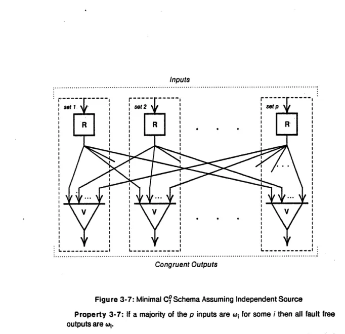
Figure 3-7: Minimal Cf Schema Assuming Independent Source 39
Figure 3-8: Failure of a C1 Schema with Two Faults 41
Figure 3-9: Minimum Fault Set Implementation of Cf 43
Figure 3-10: Minimum Stage Cf 45
Figure 4-1: Two Nondeterministic Operators 51
Figure 4-2: Decomposition of Programs into Lo Fragments 52
Figure 4-3: Prior Orderings from Dependencies and Timing Paths 53
Figure 4-4: Time-out Test as a Timing Race 55
Figure 4-5: Hazardous Redundant Time-out Test 56
Figure 4-6: Restoring Buffer with Time-out 57
Figure 4-7: A Canonical Bounded-Time T-Cq Congruence Schema 58
Figure 4-8: Standard Representation of a Canonical TC' Schema 59
Figure 4-9: Correct Implementation of Redundant Merge 60
Figure 4-10: Self-Synchronization of Redundant Edges 63
Figure 5-1: Simplex Model for a Demand Driven Sensor 68
Figure 5-2: R1 Model for a Demand Driven Sensor 69
Figure 5-3: Fault Set Assignment in the C.S. Draper Triplex FTP 71
Figure 5-4: Correct Model for a Cross-Strapped Sensor 72
Figure 5-5: Absolute Clocking of a Program 73
Figure 5-6: Physical Clocks from a Self-Synchronizing Schema 74
Figure 5-7: Example SIFT Configuration for f = 1 76
Figure 5-8: Simplified NASA/IBM Space Shuttle Computer System 79
Chapter One
Introduction
The direct replication of digital modules, known as modular redundancy, is a popular technique for improving the reliability of digital systems [1] [2] [3]. Most implementations are for real-time control systems, such as aircraft, spacecraft, and critical process control. In these systems, a loss of computational capability can directly lead to substantial financial and
human costs. In applications of interest, the probability that the system will catastrophically fail, due to loss of control functionality, must be less than one part in 109 per operational hour. Despite the diversity of applications and the frequency of attempts, there is a paucity of theory and practice for the analysis, design, and development of highly reliable digital systems. In fact, the vast majority of approaches are ad hoc and suffer from serious theoretical shortcomings.
Basic results associated with aspects of redundant computation and computer synchronization, however, have been developed in the excellent work of Lamport, Shostak, and Pease [4] [5], and Davies and Wakerly [6]. These results have been correctly exploited
only by a minority of fault-tolerant system designs, notably SRI's SIFT computer system [7], and C.S. Draper Laboratory's FTMP [8]. A paper design of a packet switch communication
architecture by Clement Leung of M.I.T. [9] contains some improvements and restrictions, but is rooted in substantially the same principles.
Unfortunately, no uniform theories for the systematic analysis and construction of general redundant systems has evolved from these efforts. An engineer interested in constructing a fault-tolerant system faces a bewildering array of ideas and choices [10] [3], most of them
incorrect. Even the above implementations are burdened by excessive complexity or synchronization requirements (e.g., FTMP), or severe inefficiencies (e.g., SIFT). A simple yet provably correct engineering model for the design and analysis of highly reliable redundant digital systems is clearly called for.
1.1 The Data Flow Approach
The correct design of a fault-tolerant system must consider the interactions of algorithms with imperfect hardware. The problem is not separable. Algorithms must be sensitive to aspects of the hardware while hardware design must provide the resources for the correct execution of the algorithms. This report develops a unified framework for the synthesis and analysis of highly reliable redundant systems.
Unfortunately, commonly used models of computation do not mesh well with models of distributed physical resources and communication interconnection. While von Neumann models and associate imperative languages have, in general, been very successful, the rigorous extension of these models to distributed programs is often intractable. Data flow computation models [11] [12], however, provide a very well-suited framework on which to impose the necessary hardware abstractions of physical dispersion and interconnection. In addition to unifying the hardware and software under a single analytic paradigm, data flow inherently lacks any requirements for centralized and/or synchronous control.
The problem in fault-tolerance is to specify the interconnection and communication between computational elements. Data flow is the disciplined study of such interconnections. One expects that data flow languages and graphs can provide a rigorous foundation on which to formulate and implement fault-tolerant systems.
In the proposed hybrid model, data flow operators are grouped into sets called fault sets which correspond to the physical processing sites which fail independently of each other. Edges in the dataflow graph which connect fault sets are called interconnection links. Faults may propagate from one fault set to another only through corrupted data on the interconnection links. That is, a fault in set .A can only. cause erroneous operation in a set S
by giving the operators in S 'bad' data, not by changing the functionality of S.
This model allows complete data flow analysis of fault-propagation. Outputs from fault sets which are assumed to have failed are replaced with an arbitrary stream of special tokens called token .fragments. Similarly, the hardware designer can extract the driving design features of the distributed system: .the number and nature of independent modules that need to be designed, and the nature and topology of the interconnection.
redundancy. In other words, we test the validity of an output by comparing it for an exact match with a redundant output. We term any redundant system in which redundant outputs may be bit-for-bit compared to detect failures as congruent. This is to be contrasted with more semantically rich tests such as reasonableness tests which attempt to determine whether an output is "reasonable" given some knowledge of the function and inputs.
We assert that congruent active redundancy has the lowest semantic content and offers the highest reliability of any fault detection and isolation scheme for deterministic systems. In fact, we are able to transform any data flow program into a redundant model which can be
implemented to yield a prescribed level of reliability.
This ability is not as trivial as it might seem at first glance. Informal reasoning about redundant systems has often proven disastrous. There are many systems which have been built and plan to be built [13] [14] [15], and yet do not meet the necessary conditions of this theory. As a result, the systems may possess single point failures which invalidate analysis of effectiveness.
1.2 Problem Development
Chapter Two lays the framework for the simplex source programs, programs which assume a perfect machine, that will be transformed into a redundant model, a data flow language with hardware abstractions The source program is given in the form of a directed graph. These graphs are interpreted as a recursive connection of monotone and continuous functions. The functions are the graph nodes and map histories of data on the input edges to histories of data at its outputs. A complete partial ordering is imposed which is a naturally extended prefix ordering of these histories. The notions of fault sets and interconnection
links are also developed and a general fault model, token fragments, is introduced.
Chapter Three develops construction rules for correct fault-tolerant graphs. The need for
input congruence is established. This is a statement that all fault-free redundant graphs must
have identical inputs for the outputs to be identical. A canonical model schema, known as a
congruence schema, is developed. This schema guarantees input congruence for a specified
Chapter Four presents techniques for incorporating nondeterministic operators. Such operators are necessary for "time-out" tests, which are essential in real time systems. The concept of an event, the receipt of a token by an operator, is introduced. Correct implementation of nondeterministic functions is cast as a problem of generating a consistent time-total ordering of selected events at redundant sites. A completely distributed
synchronization technique is developed which, without the need for a system of global clocks,
interactively bounds the time-skew between similar events.
Chapter Five examines applications. This includes models for cross-strapped sensors which may be independently "read" by several processing sites, physical clocks and time scheduling. Several current high reliability systems are briefly critiqued using the theory developed in this report.
Chapter Two
Simplex and Redundant Programs
Our goal is to take an arbitrary (but well-formed) dataflow program, the simplex source, make it redundant, and impose the necessary restrictions on the physical implementation so that it is fault-tolerant. The source program is given in the deterministic language Lo, and the
programmer assumes that it will operate on a perfect machine. To make it tolerate hardware faults, the source program is replicated, and the resulting redundant program is described by the language Ro. Finally, Ro programs are augmented with the salient features of a physical
implementation: the effects of a fault, the ability to physically isolated selected operators, and aspects; of the data communication protocol between processing sites which fail independently of each other. The result is a model of the fault-tolerant system to be implemented.
This chapter presents the syntax and semantics of the languages Lo and Ro, and presents
abstractions of the physical implementation. Later chapters will give the transformation algorithms that take simplex source programs and translate them into a model of system that will continue correct operation in the presence of a specified number of faults.
2.1 Source Language,
Lo
The following syntax and semantics for the source language, Lo, are largely due to Kahn
[16] and Manna [17]
We are given the source as a simplex program.
Definition 2-1: A simplex source program is a program that is written in the source language Lo, and which assumes it is operating on a perfect machine.
The whole problem is that physical machines are not perfect, they are prone to faults. Our techniques need not bother the source program writer, however. They can automatically transform a simplex source program into a redundant one which operates correctly in the
presence of a specified number of independent faults.
It is important to separate the problem of the correctly executing program from the correctly executing system. For instance, we can offer no assurances that the source program is correctly written and will yield meaningful results. Nor can we guarantee the correct operation (or failure detection) of an input since the generating sensors are usually
stochastic and can not be directly compared. Any sensor testing must be done by the
program since the semantics are too rich to characterize here. We shall only generate a reliable vehicle on which to execute the program.
2.1.1 Syntax
A source program schema is an oriented graph with labeled nodes and edges. Incoming
edges which have no source node are called inputs. Outgoing edges with no destination node are called outputs. An example is shown in Figure 2-1.
2.1.2 Semantics
We shall treat the information flowing on the edges as tokens in the usual data flow sense. Suppose that each token (a real, integer, function, etc.) is an element of the set D. We let a
denote the empty token. The sequence of all tokens which are generated on an edge shall be called the history of the edge. All Finite sequences are naturally extended to denumerably infinite sequences by appending w's. Let the set of all such denumerably infinite sequences be denoted by Da.
Definition 2-2: A complete partial ordering on D' is defined as follows. Let a
and b be any two distinct non-null elements of D. A partial order - of elements in
D is given by
1. aCa
2. 'Ca
3. a [b and b (a
We now define the ordering on Da:
Let a E Do = <(a,a 2 ...>; b E D4 = (bl,b2... >
,.inputs
... inputs
h
outputs.:: ...
Figure 2-1: Example Source Program Schema
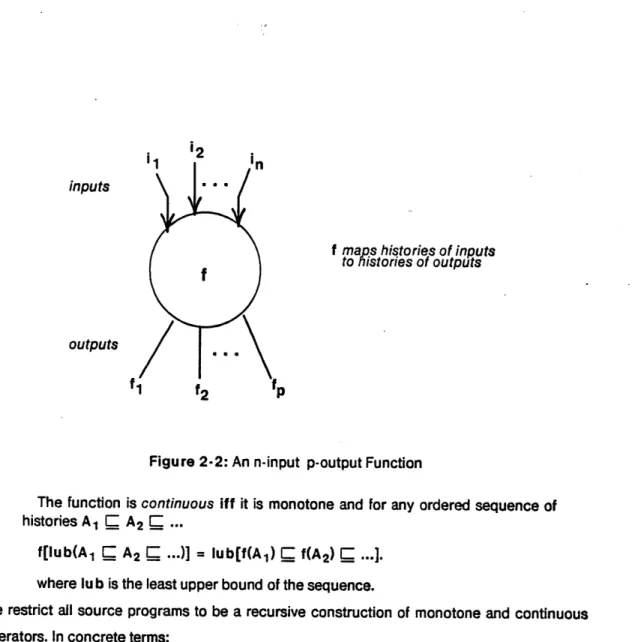
Definition 2-3: An n-input, p-output function, f, is a mapping from histories of the input edges to histories of output edges (Figure 2-2)
fl: Dol X Do2 X ... X Don, Do f2: Do, X D02 X ... X Don - Do
fp: Do, X D(2 X ... X Don- Do
A C B => f(A) Q f(B) I
where the partial order for an ordered set of sequences is defined as the conjunction of partial orders for each corresponding sequence.
' ·· '''' -''' ° . .. ,o . ..
Definition 2-4: An n-input, p-output function, f, is monotone
of input sequences A = <a, , a 2 , . . . , an> and B = <b1 , b 2 , . .., b n>
i2
inputs
outputs
f maps histories of inputs
to histories of outputs
Figure 2-2: An n-input p-output Function
The function is continuous iff it is monotone and for any ordered sequence of
histories A1 C A2 ...
f[lub(A1 C A2 C ...)] = lub[f(A) f(A) ...].
where lu b is the least upper bound of the sequence.
We restrict all source programs to be a recursive construction of monotone and continuous operators. In concrete terms:
1. Functions must be determinate, i.e., independent of the relative times of arrival of
tokens at the inputs.
2. Monotonicity restricts functions to monotonically adding information at its output,
i.e., a function may not revoke a token once it has been output.
3. Continuity prevents a function from sending output only after receiving an infinite
amount of input.
It should be noted that we allow the more general class of functions which map histories of
We have introduced all of this structure primarily to exploit the important property that a
source program schema consisting of recursive connections of monotone and continuous functions is itself monotone and continuous [16].
2.1.3 Input Robustness of Lo Programs
Even though the simplex source programmer is not concerned with failures of the machine which is executing the program, he must deal with the possibility that certain inputs to the program are erroneous. That is, it is the responsibility of the source program to produce meaningful results even when certain of the inputs have failed. Usually, this is done by employing redundant inputs to measure those quantities which are of vital importance to the correct operation of the system. Other times, the malfunctioning of the input may sacrifice system performance, but operation is still within acceptable bounds so we shall say the program is producing meaningful results. In any case, Lo programs must have the ability to deal with certain combinations of erroneous or meaningless inputs.
All L0 programs assume well-formed tokens at the inputs, whether these sequences are
meaningful is extremely context sensitive. We attempt to characterize these semantics in a neutral way, the valid input space for Lo programs.
Definition 2-5: For any Lo program with n inputs the valid input space is
Tp C DjI X Dw2 X ... X D'n such that if the histories on inputs to the program
<I.I, i2,..., in>) E rp then the outputs of the program are meaningful.
The explicit determination of Vp is usually intractable. Instead, we are only interested in the
structure of 1p for our analysis. We seek the ability of an L0 program to produce meaningful results when certain inputs are replaced with an arbitrary history. That is, the correctness of the program is insensitive to certain combinations of arbitrary input failures. For example, suppose the program requires temperature data and employs a triple redundant sensor. The temperature used is the median value of the three readings. Thus if two sensors are functional, we can substitute arbitrary failures for the third sensor and the program should still produce meaningful results (if the temperature is differentiated a better filter is required. However, the results may not be identical to the unfailed case.
This structure is characterized by an abstraction of the valid input space.
Definition 2-6: The robust input failure direction set, Vp, for an Lo program P
with n inputs, describes all combinations of inputs which can be replaced with arbitrary histories and still be elements of ip. That is,
<I, k> E Vp if for any <vl, v2,..., v1,..., Vk,...Vn> that correspond to fault-free inputs,
then <vl, v2,...,dl,..., dk,...vn> E
rp
VdI,dk E D'.This simply says that if (I, k> E, then the program will produce correct outputs when all inputs are fault-free except I and k, which may be replaced by arbitrary sequences.
2.2 A Language to Express Redundancy:
Ro
The source language has no constructs for expressing redundancy or physical implementation. Therefore, we cannot meaningfully ask the question: Is a given Lo program
fault-tolerant?
Ultimately, we will take a source program, replicate it, disperse the replicated copies to independent processing sites, and provide the necessary "glue" to ensure that all fault-free copies will produce identical outputs. The first step is to express the process of replication and provide the operators required for connecting redundant programs together. We do this in a language called Ro. Our automatic procedures for making a program fault-tolerant are
transformations from Lo to Ro .
2.2.1 Ro Program Graphs
We simply present Ro here with a minimum of justification for the extra operators we have
added. There are four elements in the language Ro:
1. Program instances, which are complex nodes corresponding to the simplex
source program,
2. Voters, which output tokens that correspond to a majority of input tokens,
3. Restoring Buffers, which are simply identity operators but will have certain signal
restoring properties given later, and
4. Edges, which connect together the program instances, voters, and restoring
Definition 2-7: A Ro program is a directed graph of recursive connections of Lo program instances, voters, and restoring buffers.
We note that Ro programs have the same semantics of Lo programs, given no failures.
2.2.2 LI) Program Instances
We need a way to represent the replication of Lo programs. Because Lo programs are
monotone and continuous functions of their inputs to outputs, we can collapse the entire source program, say P, into a single node and still maintain the semantics of Lo. The
incoming edges to a node P are the inputs to the program P, while the outgoing edges correspond to the outputs. Each instance of P in an Ro program is an instance of P. The level of redundancy in Ro is simply the number of instances of P.
2.2.3 Voters
We will often have a need to reduce a set of redundant streams of tokens down to a single stream. The resolution of the redundant copies is done by a majority operator, or voter, which is a monotone and continuous Ro function. An example is shown in Figure 2-3.
abc
Voter: o:= a if a=b
else b if b
=
celse c if c = a
err otherwise.
Figure 2-3: 3-Input Voter Note that a p-input voter is defined as:
output : = inputi if inputi is equal to at least 1 + p div 2 other inputs,
error if there is no such input.
That is, the output is the majority of the inputs, an error value if there is no majority, or w if the decision is not possible with the available inputs. It is easy to verify that this function is
2.2.4 Restoring Buffers
A restoring buffer is simply the identity function for well-formed tokens. Later, we shall
require restoring buffers to have particular implementation properties. Its schematic representation is shown in Figure 2-4.
R Restoring Buffer: o := I
0
Figure 2-4: Restoring Buffer Schematic
2.2.5 External Inputs and Redundant Outputs
We shall say that any edges in an Ro program which have no source node are the external inputs to the program, while edges that have no destination node are outputs. Those outputs
which correspond to similar edges from redundant program instances are called redundant
outputs. In general, the external inputs to an Ro program correspond to those inputs of a
simplex source program if it were operating on a perfect machine.
2.3 Abstracting the Implementation: Fault Models, Fault
Sets, and Links
Even though Ro can represent the replication of Lo source programs, we still cannot tell
whether an Ro program is fault-tolerant. Since our formulation of faults includes anomalous
system behavior due to hardware failures (we assume the source program is correctly written), we can discuss the fault-tolerance of a program only after certain important characteristics of the implementation are known. When an Ro program has been augmented with the necessary abstractions we call it a model of the system to be implemented.
Our assumptions of the underlying implementation are as follows:
1. Operators may be grouped into fault sets which correspond to dispersed physical
sites which fail independently of each other.
2. Communication between fault sets is restricted to occur only through
interconnection links, which have two important properties:
a. The interconnection topology is fixed. A destination fault set always knows the source of incoming information.
b. Information only flows in the direction of the edges. A faulty destination set
cannot induce a source set to fail via link which is directed from source to destination.
3. Faults propagation between fault sets can only occur through the exchange of
information on interconnection links, and the range of possible data that faulty set may produce is totally captured by the fault model of token fragments
Briefly, the semantics of a fault are characterized by the fault model of token fragment. Tokens and token fragments are the only method for communicating information, and thus control, between fault sets, and they travel only along interconnection links.
2.3.1 Fault Sets
Implementing an Ro program requires the mapping of the function nodes and edges onto
specific hardware. Any hardware is suceptable to threats [3]. These are stresses which produce anomalous (i.e., non-functional) conditions. Threats may manifest in many forms: normal environmental threats such as component aging, abnormal environmental threats such as transients, or software/hardware design flaws. Faults are the anomalous conditions resulting from threats. A fault model is a functional description which captures important aspects of expected faults.
Any hardware design must assess the class of threats which the redundancy will be expected to handle. We then partition the system into independent fault sets, each set having
independent failure statistics from the others. Formally,
Definition 2-8: A fault set .A is a collection of nodes and edges and a failure
rate XA such that,
1. A threat which effects the set can cause a malfunction of any and every
2. Given fault sets A and S with failure rates XA, X1 respectively. The joint failure rate (i.e., the probability that both 4A and S will fail within a unit time interval) is given by XAB = XAX B.
2.3.2 Interconnection Links
Fault sets abstract our intuitive notion of physical isolation. Generally speaking, functions implemented on one processor will be in a different fault set from functions implemented on another, if suitable isolation (e.g., electrical and electro-optical isolation) is engineered
between the processors. If these processors exchange information then the malfunction of one processor, by generating faulty results, might very well cause the other to compute irrational results. The second processor is still fully functional (e.g., it can still add). The
primary goal of fault-tolerant system design is to prevent the malfunctioning of a limited
number of units to cause other healthy units to obtain incorrect results.
Clearly the way a malfunctioning unit may influence good units is through the exchange of data and the exercise of control. Data flow models have the virtue that there is no separate control mechanism. Thus all effects of a malfunctioning unit upon good ones can be expressed purely in terms of information exchanges. This leads to the second important feature of Ro models:
Definition 2-9: The edges which join nodes which are in different fault sets are
called interconnection links. These links are abstractions of the real communication medium. We demand two implementation properties of these links,
however:
1. The source of information (i.e., which fault set) is always known by a good destination fault set. Specifically, we do not allow outputs from set A to be
confused with outputs from set S when used as inputs to any good set C. 2. Information only flows in the direction of the edge. If handshaking is used,
we cannot permit a faulted destination set to interfere with a good source set's ability to communicate with other good sets.1
These two properties, although seemingly benign, are essential for correct system operation. The communication mechanisms must be carefully engineered to ensure that they are met.
1
We can certainly include handshaking in our dataflow but this will tend to obscure its generality. In any case, one will quickly determine that condition (2) has to be met by the handshaking protocol so we are better off assuming that it is met a priori.
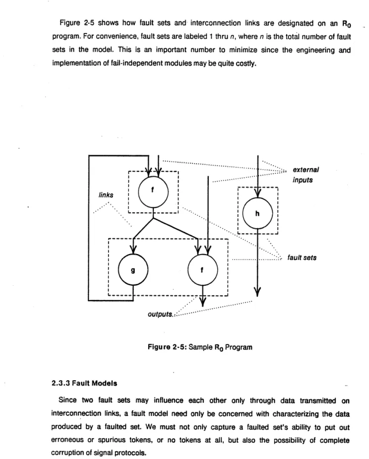
Figure 2-5 shows how fault sets and interconnection links are designated on an Ro program. For convenience, fault sets are labeled 1 thru n, where n is the total number of fault sets in the model. This is an important number to minimize since the engineering and implementation of fail-independent modules may be quite costly.
;;, external
inputs
;. fault sets
Figure 2-5: Sample Ro Program
2.3.3 Fault Models
Since two fault sets may influence each other only through data transmitted on interconnection links, a fault model need only be concerned with characterizing the data produced by a faulted set. We must not only capture a faulted set's ability to put out erroneous or spurious tokens, or no tokens at all, but also the possibility of complete corruption of signal protocols.
We shall say that "tokens" transmitted in the latter case are not well-formed. Our fault model is as follows:
Definition 2-10: If a fault set A. is faulted then we replace the histories of each output edge with an arbitrary sequence of tokens called token fragments, E = <e1,e2,e3,...>. A fragment is characterized by the rather insidious properties:
1. ej E DUU {} V j.
2. ej, [ ej2 for any two receivers, 1 and 2.
Property (1) states that the outputs of a faulted source set can be any arbitrary sequence of formed tokens. Property (2) captures the characteristics of tokens which are not
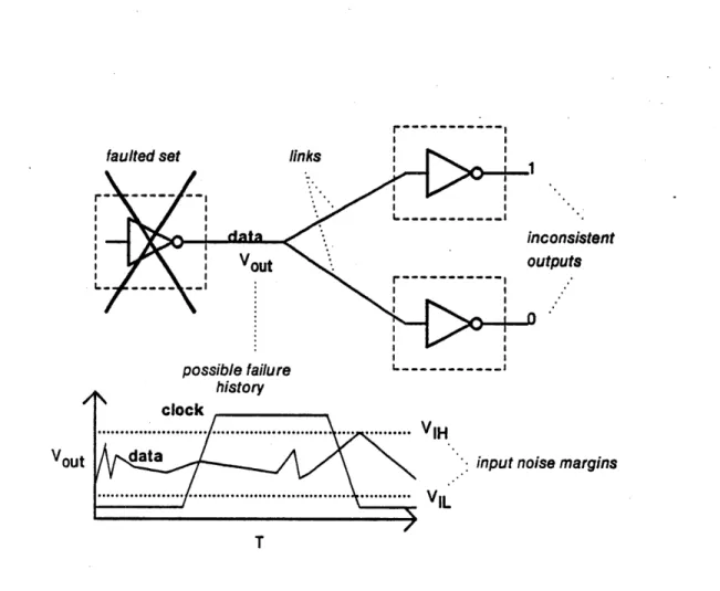
well-formed. That is, two independent observations (receptions) made of the same token ej may differ in their interpretation. This is an essential feature of digital communications which are made through noisy channels with insufficient noise margins. In this case two receivers may extract different values from the communicated data.
This ability for a failed transmitter to "lie" to unfailed receivers is the most overlooked yet potentially catastrophic failure mode of all digital systems. As such, further discussion is merited.
Disbelievers protest that "that will never happen. How can two units reading the same wire get different results?". This ignores some very common failure modes of all physical communication schemes.
Figure 2-6 shows the connection of three fault sets, A., 9, and C. The interconnection link contains two physical wires, a data line and a clock line. Assume that the data line is sampled whenever the clock line makes a low to high transition. If A fails in such at way that the signals on the data line become marginal (i.e., somewhere between the logical 0 voltage and the logical 1 voltage) then S and C could obtain a different value for any bit. A's failure
might be as simple as a bad solder joint on a pullup resistor or a failing output transistor. In
any case, this event seems quite probable and it must be considered in the analysis of any
high reliability system.
Even if heavy coding is used (e.g., Cyclical Redundancy Checks) there is still the possibility that the receivers will get different results. S might be able to recover the signal from the noise while C might detect an unrecoverable error. The results are still different.
The need for source congruence is probably the leading driver of a correct fault-tolerant implementation. It is also the most overlooked by the engineering community.
I I 7consistent utputs history clock ... ... .... ... VIH data
... ... ... VIL
Vout Sinput noise margins
T
Figure 2-6: Inconsistent Reception of a Token Fragment
2.3.4 Restoring Buffers Revisited
Now that the concept of a token fragment has been defined, the implementation requirements of restoring buffers can be presented. We desire functions which can take a sequence of token fragments as inputs, and output an arbitrary sequence of well-formed tokens. That is, we desire functions that can map
Any function which has this property is called restoring.
We remark that the design of a restoring function is totally dependent upon the signal protocols used in the system. It is, however, usually simple to create and often involves just clocking the inputs into latches.2 Restoring buffers will be used liberally in our solutions.
2.4 Summary
We have presented a very powerful, albeit determinate, language in which to express
simplex source programs, the programs we shall implement on our fault-tolerant hardware.
The language is characterized by recursive connections of monotone and continuous functions which map histories of tokens at inputs to histories of tokens at outputs.
The language, Ro, is an extension of Lo, and can express redundant instances of Lo
programs. We then augment Ro programs with abstraction of those hardware features which
have an effect on the fault-tolerance of the system. An augmented Ro program is called a model of the system.
In the absence of failures, the semantics of Ro and Lo are identical. We use fault sets to
model failure-independent hardware modules, and interconnection links to model the interconnection of the modules.
A fundamental property of our approach is that fault propagation from bad modules to good
is purely through the communication of data from the bad to the good. We argue that a totally general fault model for such data exchanges is characterized by arbitrary sequences of token
fragments.
The following chapters will show how to construct correct fault-tolerant systems using Ro models.
2
We don't mean to treat this property lightly. If self-clocking asynchronous protocols are used, restoring functions
require a great deal of care in design. It is often argued that such functions can never be fully realized, for even fault-free versions may contain metastable states. While we admit that this may be true, we assert that careful
Chapter Three
Making Simplex Programs Fault-Tolerant
This chapter presents procedures for transforming simplex Lo source programs to Ro
redundant programs, and then imposes the necessary implementation restrictions.
The objective is to meet a given reliability specification for the target system. This specification can be given in two forms. The fail operability form is an integer specifying the number of independent fault set failures that can be tolerated while still maintaining correct system operation. The second form is the aggregate system reliability. This is a real number specifying probability of correct system operation over some interval of time.
We first precisely define what is meant by correct system operation. This definition relies
on the concepts of congruent histories and congruent sets of arcs. It is shown that
comparison monitoring in the most powerful test for congruence which is possible in Ro.
Procedures are developed which transform Lo programs into Ro programs and meet a given
fail-operability requirement. We show that the problem of input congruence, ensuring that all fault-free redundant graphs have identical inputs, is the driver for correct system design. Ro
schemata are presented which guarantee input congruence in the presence of faults. The properties of these schemata are explored in detail.
Finally, we give a graph coloring algorithm for determining the fail-operability, the aggregate system reliability, and for exposing critical failure paths.
3.1 Overview of the Lo
to Ro
Transformation
Our principal approach to improving system reliability is through modular redundancy.
Modules correspond to fault sets that contain program instances.
Suppose the Lo program, P, as shown in Figure 3-1, is given along with a fail-operability goal of 1. That is, the implementation should be able to tolerate any single fault and remain
operational. Thus P will have to be triplicated in Ro where each instance of P is in an independent fault set.
external inputs
S... .. o... ,.
output
Figure 3-1: Example Source Program
The output devices are given the burden to resolve the redundant outputs from the three instances of P. This resolution will be through bit-for-bit comparisons of the three output lines so it is required that
(C1) Outputs from all fault free instances of P agree bit-for-bit.
Because all Ro program fragments are continuous and monotone functions, a sufficient
condition to satisfy C1 is
(C2) Similar inputs to all fault free instances of P agree bit-for-bit.
We call this the input congruence condition. It will become clear that ensuring input congruence is the leading driver in correct fault-tolerant system design. Unfailed outputs must also be correct, where correctness is relative to the original Lo program. As shown in
Figure 3-2, the external inputs must be delivered to each Ro instance of P such that C2 is
satisfied and
(C3) The inputs applied to any fault free instance of P must be valid inputs for P
in LO.
and that replacing certain inputs by arbitrary sequences of well-formed tokens also forms valid input sets. That is, P should contain algorithms for identifying or tolerating a faulty external input. This property is captured in P's robust input direction set Vp.
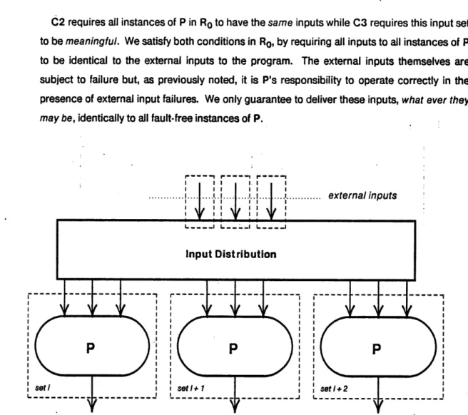
C2 requires all instances of P in Ro to have the same inputs while C3 requires this input set
to be meaningful. We satisfy both conditions in Ro, by requiring all inputs to all instances of P to be identical to the external inputs to the program. The external inputs themselves are subject to failure but, as previously noted, it is P's responsibility to operate correctly in the presence of external input failures. We only guarantee to deliver these inputs, what ever they
may be, identically to all fault-free instances of P.
S.... .... : ,etInI nIIp uI
....
.... .
....
. ...
. 1
...
external inputs
I I I I i I i I L. redundant outputsFigure 3-2: General Topology for Triplex P
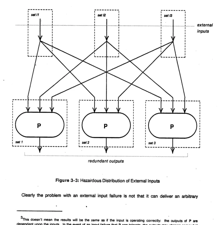
Figure-3-3 illustrates an initial solution. Here the inputs are simply distributed to the independent instances of P. The problem is in the failure of an external input. In the simplex
assumptions of Lo , P could still produce correct3 results even in the presence of selected
input failures. Now when we fail an input each P will produce correct results but the results may not be the same since a failed external input, being modeled by an arbitrary history of token fragments may be interpreted differently by each instance of P.
... ...
redundant outputs
Figure 3-3: Hazardous Distribution of External Inputs
Clearly the problem with an external input failure is not that it can deliver an arbitrary
3This
doesn't mean the results will be the same as if the input is operating correctly: the outputs of P are
dependent upon the inputs. In the event of an input failure that P can tolerate, the outputs may change somewhat but they are still acceptable and so P operates correctly.
eternal puts
sequence of tokens, but that the value of these sequences is dependent upon the receiver. This happens when signal protocols are violated and the tokens are not well-formed, as motivated in Chapter 2. To solve this problem we need functions which, when fault-free, produce only well-formed tokens. Restoring buffers have this capability.
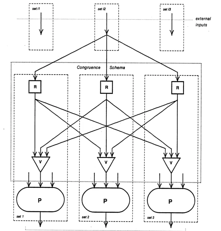
Our solution involves distributing each external input to three restoring buffers. The outputs of the buffers are exchanged and independently resolved at the input to each instance of P.
Figure 3-4 illustrates the use of restoring buffers and voters to consistently replicate an external input. The graph is similarly replicated for the remaining two external inputs. This triplex realization of P can tolerate any single failure, and still yield at least two correct and identical outputs.
The operators within the box in Figure 3-4 are an example of a congruence schema. The following sections will develop machinery for the creation and analysis of congruence schemata, as these are the distinguishing features of a correct fault-tolerant system design.
3.2 Bit-for-Bit Agreement and Congruence
Bit-for-bit agreement among redundant outputs is an imposing goal of modular redundant designs. Formulations of redundant systems where only approximate agreement among redundant outputs is required makes it substantially more difficult, if not impossible, for output devices to generate correct commands. In our case, any single bit disagreement between two redundant outputs will always imply a fault in one, or both, sources. Combinations of pairwise comparisons of outputs will be used to isolate and mask faults. Isolating a fault means to correctly determine which fault set has faulted. Masking a fault stops the bad data produced
by a faulted set from propagating through the system. Selecting the median value of three
signals, for example, will only mask a bad signal. Multiple pairwise comparisons, voting, of the same signals, if applicable, will both mask and isolate the bad signal.
This section formalizes the concepts of bit-for-bit agreement and pairwise comparison tests in terms of Ro.
I i Ie
seh
I I~__~
redundant outputs
Figure 3-4: A Correct Triplex Version of P
ernal uts
3.2.1 Congruent Sets
Here we precisely define bit-for-bit agreement in the semantics of Ro. We shall say that two
histories are congruent if they are the same point in D". A set of edges form a congruent set
if the corresponding histories are all congruent. Formally,
Definition 3-1: Histories a,b E D~ are congruent, a - b, iff
a b and bC a.
Definition 3-2: Edges e1, e2, ..., e, with histories el, e2, ... , en form a
congruent set iff
ei = ej Vi,j.
We will sometimes talk of a congruent set of histories which we mean to read: the edges
corresponding to these histories form a congruent set.
3.2.2 Congruence Tests
Since we shall use pairwise comparison to isolate and mask faults it is important to precisely understand the properties of this test. We wish to destroy the notion that such comparisons and associated majority logics are heuristic. Rather, they form a rigorous basis for provably correct fault-tolerant systems. The pairwise comparison test of two histories is defined as the weak equality function for Ro .
Definition 3-3: A pairwise comparison test of two histories a = (a1, a2, ...),
b = (bl, b2, ...) is the weak equality function on each element: at = bi is
1. w1 if a, or bi is w
2. true, if ai is b,
3. false1 otherwise.
We write a # b if (ai = bi) is falsei for any i and a = b otherwise.
We now prove that a pairwise comparison test is the strongest test for congruence that can be formulated in Ro .
Theorem 3-1: For any two histories a and b:
1.a* b ' = a b
Proof:
1. a b => 3 ai, bi # 3 ai =bi = a Si b.
2. By contradiction. Suppose there exists a continuous and monotone function F(a,b) which decides a = b. That is, F generates falsei whenever ai 1b, or
bi [ai and truei otherwise. Let a, = (1, 1, ... ), a, = (w, o .. .) then
<a,, a,> E <a,, a1> =: F(a,, a,) C F(a., a1) since F is monotone.
However, F(a., a,) = <true, true,...> and F(a,, a1) = <false, false,...>.
And <true, true,...) >
<false,
false,...>.This implies that F is not monotone. Therefore, no such function exists in Ro. 0
In some sense this exposes an inherent weakness in the seemingly powerful formulation of
Ro. That is, Ro programs lack the ability to detect missing tokens. Detection requires a
nondeterministic merge, which is not a function in Ro. Such merges will be allowed in R1,
which will be presented in the next chapter. When nondeterministic operators are permitted, the problem of creating congruent sets is considerably more difficult, and a total ordering of system events, synchronization, is required.
3.3 Testing R
0Models for Correctness
The ultimate measure of the systems which we produce is a probability of correct operation. Correctness of an Ro program is defined in terms of its outputs, and whether the
redundant outputs are congruent with respect to the same edges in a perfect Lo simplex
program.
3.3.1 Input Robustness and Correct Operation of Ro Programs
When we transform an Lo program to Ro we group the inputs into fault sets which
correspond to the implementation. Any input from a good fault set is assumed to lie in the valid input space of the Lo program. Correct operation of an Ro program is readily defined.
Definition 3-4: An Ro implementation of an Lo program P is correctly
operating if a majority of redundant outputs form a congruent set with the outputs
of a perfect simplex version of P.
all fault-free redundant outputs must be identical. We can assure congruent outputs of all fault free instances of P by providing congruent inputs. We can't test for membership to Ip directly, but we can use the fact that if all but inputs j, k, I,... are congruent with fault free external inputs and <j, k, I,..> E Vp then the inputs are in the valid input space 1(p.
3.3.2 Fail-Operate Specification
The fail-operability specification is now easy to precisely formulate given the definition of correct system operation.
Definition 3-5: An Ro implementation of the program P with n independent
fault sets is fail-opt if for any f fault sets with output edges replaced by arbitrary sequences of token fragments, the system continues correct operation.
In our models, fault sets can influence one another only through the exchange of data on output edges, and we suggest that arbitrary sequences of token fragments completely characterize the range of these failures. Our definition of fail-operability describes precisely the number of independent fault set failures that can be tolerated by a given implementation. Thus we believe that the above definition completely captures the meaning of "fault tolerance". Later, we shall give a graph coloring procedure for determining the fail-operability figure for any Ro program.
3.3.3 Aggregate System Reliability
The primary reason that a system should tolerate faults is that individual component or module reliability is insufficient to meet a system reliability specification. It is of utmost importance, then, that we are able to extract an aggregate system reliability number for our implementation.
Theorem 3-2: Given an Ro program with n fault sets and failure rates X1, X2,...,
•n. The aggregate system failure rate Xs, can be determined by the following algorithm.
Initialize sys: = 0.
For all f: 0 < f < n test the system for correct operation against failures of each
combination of f units. If the system does not correctly operate then update
Xsys"
= Xsys + Xil Xji2...j(1-kl)( 2)... (1-k(nkf)) where the
Xis
correspond to each of the f fault sets that are assumed failed and the XkS correspond to the remaining n-f fault free sets.sets. (There are 2' of them.) Therefore the probability of any combination occurring in a set of combinations is the sum of the probability of occurance of each combination in the set. In our case the set of interest is defined by the attribute of correct system operation.
Since the underlying events are all independent, the probability of occurance of any combination is the product of the unreliability, X, of each failed set times the product of the reliability, 1- , of the remaining fault free sets.
0
Note that dominating terms in the sum reveal the critical failure paths of the system. The procedure, although correct, is much more exhaustive than it needs to be, given the domination of these terms. It is possible to extract these paths to obtain a good approximation of the unreliability of the system. Our intent here is to show that our model provides unambiguous information for extracting the aggregate system reliability.
It is possible to lend a probabilistic structure to Vp which describes the coverage of input failures by P. This would include the probability of misdetection and false alarms. Such additional information is easily incorporated into our model.
3.4 Required Level of Redundancy
It is important to determine the number of independent instances of a program4 which are
needed to meet a given fail-operability goal. Each instance is "expensive" in that it represents real computation and physically separate pieces of hardware. Thus we would also like to know what price we are paying for the modular redundancy approach. Are there any other approaches that yield analytically correct results but with less hardware?
By the definition of system correctness, a majority of redundant outputs must be congruent
and correct. An arbitrary fault can cause an output to not be congruent and, more importantly, faulty outputs can "collude" to form congruent sets of their own. So if input congruence and correctness are satisfied for each fault-free unit, to tolerate f independent faults requires, in our case,
p Ž 2f + 1,
where p is the number of independent instances of the Lo source program P. Clearly, even in
the presence of f faults, a majority of fault-free units are producing congruent outputs. Thus application of pairwise comparison tests to all pairs of outputs will always resolve a correct output.
This also implies that n, the total number of fault sets is bounded by
n >p>2f + 1
If n ) p then the remaining n - p fault sets are not directly associated with the computation of
P, but with some other function or with the external inputs. The p sets associated with the computation of P are the "processors". Thus we conclude that we need a minimum of
p = 2f + 1 independent sites computing P.
This constraint may seem excessive. However, the following result from testing theory [18] shows that this is indeed a minimum for the correct isolation of f failures using any test.
Theorem 3-3: [Preparta et al., 1967] Any system S composed of n independent units can correctly isolate f simultaneous faulty units by mutual testing only when
n > 2f + 1.
Mutual testing is where unit A can apply a test to unit B to diagnose faults in B. If A is itself faulty then the result of the test is arbitrary. In our case, we say that a unit is faulty when its output ceases to be congruent with other good units. Thus our test, the weak equality test of two histories a = b, is a reflexive test. Unit A tests unit B through the same test as B tests A. In any case, this theorem establishes the bound on p to be at least 2f + 1. Since we can meet this bound strictly, majority logics are in fact optimal in terms of the number of cotesting units required.
Unfortunately, the number of independent fault sets, n, required to maintain congruent inputs to all fault-free instances of P is strictly greater than p. This is not a result of testing theory, however. One quickly finds that the hardware, e.g., testing theory approach to fault-tolerant system pays little attention to the types of algorithms that will be implemented. Similarly, the algorithmic approach often misrepresents or ignores important aspects of hardware design.
Maintaining congruent input sets falls in the "algorithmic" side of reliable system research, and is often called the Byzantine Generals Problem. Results here [4] [5] show that the
number of independent processors, p, required to maintain congruent inputs to all fault-free
Theorem 3-4: [Pease et al., 1980] A system S composed of n independent units can ensure congruent edges in all fault-free units only when n > 31 + 1.
The two results seem to be contradictory, however, both are correct within their assumptions. The elements of the theories which apply to our model reduce to
p>2f + 1
n >3f + 1
Thus p independent instances of P are required to correctly isolate any f faults in the computation of P. The remaining n -p fault sets are required to maintain congruent inputs to p processing sites. We note that most fault-tolerant systems which employ congruent processing have 2f + 1 processing sites but rarely have the 3f + 1 fault sets required for
correct distribution of external inputs. Therefore, these systems contain failure modes whereby the occurance of f simultaneous faults can cause a complete system failure.
3.5 Ro Schemata For
Congruent
Inputs
In this section Ro schemata are developed which guarantee congruent distribution of a
simplex input in the presence of a given number of faults. As previously illustrated, the congruent distribution of a single simplex source of data is the driving requirement for correct fault-tolerant system operation. In particular, when the simplex source is itself faulted, inconsistent views of the value of the source are possible unless some congruence schema is employed.
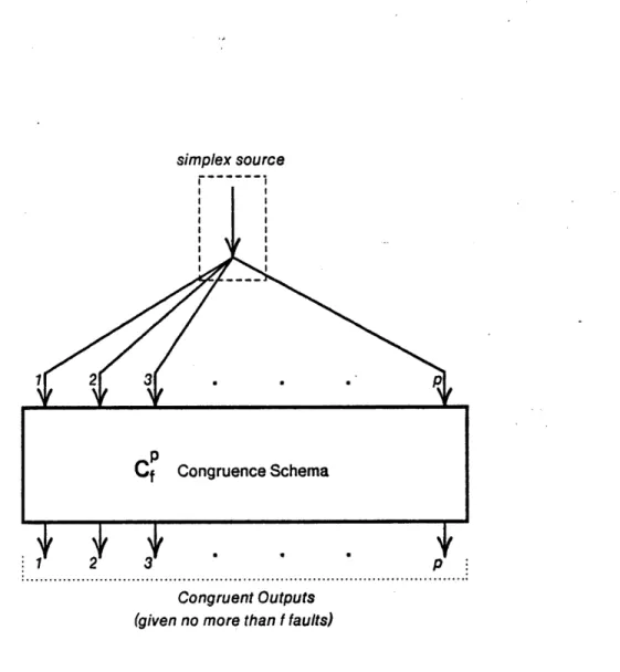
Definition 3-6: CfPis a p-input, p-output Ro congruence schema if distribution
of a simplex source to all p inputs guarantees a congruent representation of the input at all outputs in the presence of I independent faults, including the simplex source.
Figure 3-5 gives a schematic representation of a Cpcongruence schema.
For example, the solution presented in the overview, Figure 3-4, constructed a C3
congruence schema which successfully delivers an external input to the three instances of P in the presence of any single failure.
simplex source
I I
Congruent Outputs (given no more than f faults)
Figure 3-5: Schematic for a CfCongruence Schema
3.5.1 Cj Schemata
A CV' schema can tolerate a simplex source failure or a set of internal, i.e., inside Cý, failures
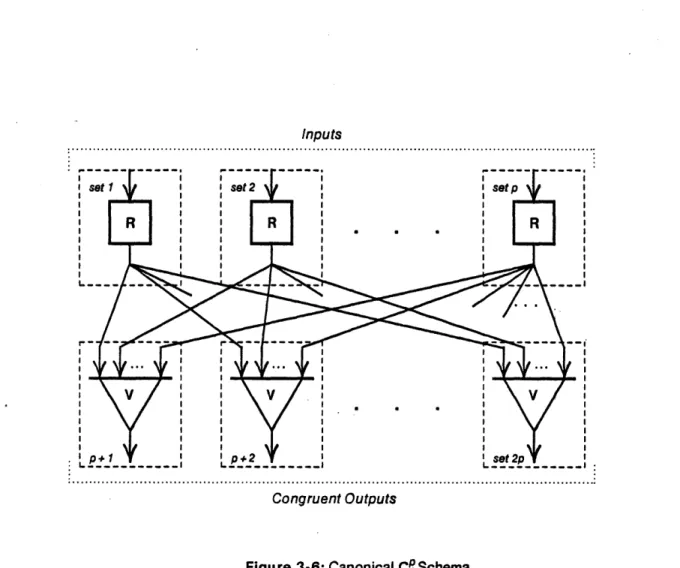
and still deliver congruent results to the p outputs. The properties and construction of such schemata are important in that, in this section, we develop Cfschemata, those which deliver p congruent outputs in the presence of f faults, from recursive constructions of Cq schemata.
Figure 3-6 gives the canonical implementation of a CP schema.
The numbers by the input and output arcs designate the fault sets to which the associated operator, a restoring buffer or voter, belongs.
Inputs
Congruent Outputs
Figure 3-6: Canonical CP Schema
Because each output is used to drive an instance of P, the output fault sets, i.e., the fault sets corresponding to the voters, are usually the same as the instance of P to which they are connected. When the source is originating from a different set than any of the output sets, fault sets of input restoring buffers may be paired with fault sets of the output buffers. We call this, see Figure 3-7, a minimal realization of the schema, because the total number of fault sets required is a minimum with respect to theorems 3-3 and 3-4. We now give several important properties of Cq schemata, either canonical or minimal.
Property 3-5: All C' schemata are monotone and continuous.
This trivially follows from the fact that both restoring nodes and voters are monotone and continuous functions. Direct consequences of 3-5 are
Inputs ... o ,... ... ... ... ,... ,... ,... ... ,... o... ,... I I 1 I I I I I I I I I I I I I I I I I I I i i I ,r :... . ... ... .. .... . ... . ... . . ... .. Congruent Outputs
Figure 3-7: Minimal Cq Schema Assuming Independent Source
Property 3-7: If a majority of the p inputs are wi for some i then all fault free
outputs are wi.
These properties will be exploited in the next chapter but we note that property 3-7 alludes to the most serious limitation of Ro. That is, it is impossible to detect the divergence of a simplex
source. Clearly, the divergence of a source is quite a common failure mode and almost all failure detection and isolation algorithms for external inputs require a "time-out" test. This test is not available in Ro because such tests are nondeterministic and therefore not functions
of histories of inputs to histories of outputs. However, the structures developed here will be extensively exploited in the construction of congruence algorithms for nondeterministic systems. •
The following properties are extremely useful in constructing general Cfpschemata. They apply to both canonical and minimal implementations. The positive ones are: