READ THESE TERMS AND CONDITIONS CAREFULLY BEFORE USING THIS WEBSITE.
https://nrc-publications.canada.ca/eng/copyright
Vous avez des questions? Nous pouvons vous aider. Pour communiquer directement avec un auteur, consultez la
première page de la revue dans laquelle son article a été publié afin de trouver ses coordonnées. Si vous n’arrivez pas à les repérer, communiquez avec nous à PublicationsArchive-ArchivesPublications@nrc-cnrc.gc.ca.
Questions? Contact the NRC Publications Archive team at
PublicationsArchive-ArchivesPublications@nrc-cnrc.gc.ca. If you wish to email the authors directly, please see the first page of the publication for their contact information.
NRC Publications Archive
Archives des publications du CNRC
This publication could be one of several versions: author’s original, accepted manuscript or the publisher’s version. / La version de cette publication peut être l’une des suivantes : la version prépublication de l’auteur, la version acceptée du manuscrit ou la version de l’éditeur.
Access and use of this website and the material on it are subject to the Terms and Conditions set forth at Smoke movement in egress routes in a high rise building
Lougheed, G. D.; Fu, Z.; Hadjisophocleous, G. V.; Carpenter, D. W.; McBride, P. J.
https://publications-cnrc.canada.ca/fra/droits
L’accès à ce site Web et l’utilisation de son contenu sont assujettis aux conditions présentées dans le site
LISEZ CES CONDITIONS ATTENTIVEMENT AVANT D’UTILISER CE SITE WEB.
NRC Publications Record / Notice d'Archives des publications de CNRC: https://nrc-publications.canada.ca/eng/view/object/?id=5d1ed732-4267-4f00-ab40-85c1fbde9cbf https://publications-cnrc.canada.ca/fra/voir/objet/?id=5d1ed732-4267-4f00-ab40-85c1fbde9cbf
http://www.nrc-cnrc.gc.ca/irc
Sm ok e m ove m e nt in e gre ss rout e s in a high rise building
N R C C - 4 2 8 3 7
L o u g h e e d , G . D . ; F u , Z . ; H a d j i s o p h o c l e o u s , G . V . ; C a r p e n t e r , D . W . ; M c B r i d e , P . J .
O c t o b e r 1 9 9 9
A version of this document is published in / Une version de ce document se trouve dans:
Proceedings 3rd International Conference on Fire Research and Engineering, Chicago, IL, October 4-8, 1999, pp. 27-38
The material in this document is covered by the provisions of the Copyright Act, by Canadian laws, policies, regulations and international agreements. Such provisions serve to identify the information source and, in specific instances, to prohibit reproduction of materials without written permission. For more information visit http://laws.justice.gc.ca/en/showtdm/cs/C-42
Les renseignements dans ce document sont protégés par la Loi sur le droit d'auteur, par les lois, les politiques et les règlements du Canada et des accords internationaux. Ces dispositions permettent d'identifier la source de l'information et, dans certains cas, d'interdire la copie de documents sans permission écrite. Pour obtenir de plus amples renseignements : http://lois.justice.gc.ca/fr/showtdm/cs/C-42
Smoke Movement in Egress Routes in a High Rise Building
G.D. Lougheed, Z. Fu, G.V. Hadjisophocleous and D.W. CarpenterNational Research Council Canada Ottawa, ON K1A 0R6
P.J. McBride Ottawa Fire Department
Ottawa, ON ABSTRACT
Recently, a series of full-scale fire tests were conducted in the NRC ten-storey tower facility during which corridors on the fire floor and the stair shaft were filled with smoke. These tests were part of a project with government and private sector organizations to investigate the use of positive pressure ventilation to vent smoke from high rise buildings. In this paper, the results of the initial stage of fire tests using typical residential furniture (sofas and beds) are discussed including the impact of various parameters on smoke movement in the egress routes. In addition, the experimental data is compared to the results determined using network and multi-compartment zone models.
INTRODUCTION
The importance of understanding smoke movement in storey buildings and multi-compartment buildings is well recognised. In a review of fire experience in the USA between 1987 and 1991 [1], it was shown that for most property classes, with the exception of those that care for the sick, there was a high probability of smoke damage beyond the room of fire origin. For high-rise apartment buildings, smoke damage was limited to the room of fire origin for 61.5% of fires and beyond the room of fire origin but confined to the floor of origin for 25.2% of fires, There was smoke damage beyond the floor of fire origin for 13.3% of fires. The comparable statistics for apartment buildings of all heights were 49.5%, 21.1% and 29.3%, respectively.
The potential hazard associated with the smoke produced by a fire entering building egress routes was demonstrated in three fires in high-rise apartment buildings in Ottawa and Toronto [2,3, 4]. A fire in a 20 storey residential building in Ottawa in 1983 resulted in three deaths and one person permanently injured [2]. In addition, a family of six was found unconscious in a stairwell. A fire in Toronto in a 30 storey high-rise apartment building in 1995 resulted in six deaths [4]. The fully-developed fire was in an apartment on the fifth floor of the building and the door between the fire compartment and the building corridor was left open by the occupant. All the deaths occurred in the stair shafts well away from the fire area. In the second fire incident in Ottawa in 1997 [3], the fire started in the entrance closet of an apartment on the sixth floor of a 25-storey apartment building and rapidly spread through the apartment door into the corridor. The fire department was on the scene within 5 min of the 911 call and extinguished the fire 10 min later. Shortly after the fire department arrived on the scene, occupants were instructed to evacuate the building. All occupants of the fire floor and the floor above that attempted to evacuate encountered smoke conditions in the corridors and stair shafts. Only 54% of these people managed to reach the ground level. The remaining 46% either returned to their apartments or sought refuge in other apartments.
There have been limited investigations on smoke movement in multi-storey buildings [5,6]. The difficulties in modelling smoke spread in a multi-storey building were demonstrated by He and Beck [7]. In particular, there is limited full-scale test data for use in verifying numerical models for smoke movement in stair shafts.
Recently, a series of full-scale fire tests were conducted in a ten-storey tower facility during which corridors on the fire floor and the stair shaft were filled with smoke. These tests were part of a project with government and private sector organizations to investigate the use of positive pressure ventilation (PPV) to vent smoke from high rise buildings. PPV is achieved by blowing air into a building using fans. When appropriate openings or vents are used, the airflow produced by the fan exhausts contaminants to the outside.
In this paper, the results of the initial stage of the fire tests with typical residential furniture (sofas and beds) are discussed. During this stage of the test, the smoke from the fires was allowed to fill the egress routes in the test facility. The impact of various parameters on smoke movement in the egress routes is discussed. In addition, the experimental data is compared to the results produced by a multi-compartment zone model.
TEST ARRANGEMENT Test Facility
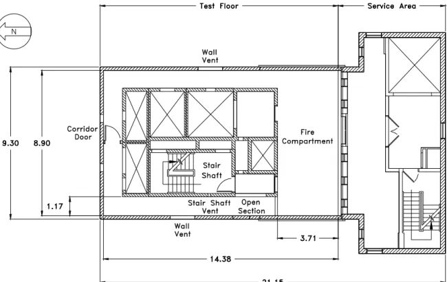
The ten-storey tower facility was designed to represent conditions of a high rise building. This facility has been used extensively for studies on smoke movement [5, 6] and smoke control systems [8, 9]. The 10-storey facility includes an experimental tower and an attached service area (Figure 1). The typical floor height is 2.4 m except for the first and second floors, which are 3.6 m high.
The experimental tower contains all the shafts and other features necessary to simulate air and smoke movement patterns in a typical multi-storey building, including the elevator, stair, smoke exhaust, service, supply and return air shafts. The elevator and stair shafts are full-sized, but the elevator shaft has no car or hoisting apparatus. The stair shaft is equipped with a standard staircase. A surrounding corridor isolates the shafts from the exterior walls, creating a typical centre core. All joints in the concrete structure are sealed to minimize uncontrolled air leakage. On the exterior walls and walls of vertical shafts, there are variable openings that can be adjusted to provide desired leakage areas of typical buildings.
For the tests in this project, a test arrangement similar to that of previous smoke movement studies was used [5,6]. In the test arrangement (Figure 1), the fire was located in a 3.9 m by 9 m compartment on the fire floor. The smoke produced during the fire was allowed to flow into a 30 m long corridor on the test floor and subsequently into the stairwell through known leakage areas including, in some tests, an open door.
Leakage openings included: two 134 by 279 mm openings between the corridor and the exterior of the building on each floor; two 146 mm diameter openings between the fire floor and the floor below; and a 132 mm by 132 mm opening between the stair shaft and the corridor on each floor. All the openings into the other building shafts in the centre core and between floors above the fire floor were closed.
Measurements included temperatures, pressures, CO and CO2 concentrations and smoke levels at various locations in the tower facility. The location of the instrumentation was as follows:
1. Thermocouples in the fire compartment.
2. A thermocouple tree in the North corridor on the seventh floor with the thermocouples located 400, 800, 1200, 1700 and 2000 mm below the ceiling.
3. A thermocouple tree in the doorway into the stairwell (the thermocouples were 400, 800, 1200, 1700 and 2000 mm below the ceiling on the seventh floor and 75, 482, 914, 1372 and 1702 mm from the top of the doorway on the second floor).
4. Thermocouples at the centre of the stairwell on all floors (the thermocouple location was at mid-height between the designated floor and the floor above).
5. Gas sampling inlets in the stairwell at the same location as the thermocouples on Floors 2, 4, 6, 8 and 10 for CO/CO2 analyzers.
6. Smoke obscuration devices at the 1.5 m height above the landing area on Floors 2, 4, 6, 10 and in the corridor on Floor 8.
For the PPV study, tests were conducted using the following fire sources: 1 MW propane burner fires and sofa fires on the second floor; sprinklered heptane pan fires and bed fires on the seventh floor. For this paper, only the results from the sofa and bed tests are discussed. Tests were conducted in both the winter and the summer to investigate the impact of stack effect on smoke movement. The other primary parameter was the time at which the exterior stairwell door and the door on the fire floor was opened. Also, in one test scenario the stairwell door on the eigth floor was left open throughout the test.
Fire Source
Seven identical new sofas and mattress and box spring sets were purchased for the test program. A preliminary calorimeter test was conducted with each furnishing item to determine its heat release rate. The heat release rates are shown in Figure 2. The ignition source was lit at 1 min.
A propane T-burner was used as the ignition source. This ignition source and its heat release (25 kW) were typical of that used for furniture calorimeter tests [10]. For the tests with the sofa, the ignition source was located at the corner formed by the seat, the arm and back of the sofa. The throw pillow that came with the sofa was placed above the burner.
For the mattress tests, the mattress and box spring was raised 200 mm above the floor using concrete blocks. The ignition source was centred on one side of the bed with the burner at the base of the box spring.
For each furnishing item, three tests were conducted in the summer and the winter using the following test scenarios:
1. Scenario 1. The stair shaft door on the fire floor was opened three minutes after ignition. This simulated an occupant leaving the building and the door not closing properly. The exterior stair shaft door was opened at 8 min simulating arrival of the fire department. At 10 min, a vent was opened at the top of the stair shaft and positive ventilation initiated.
2. Scenario 2. The stair shaft door on the fire floor was opened three minutes after ignition. The exterior stair shaft door was opened at 8 min. At 10 min, vents were opened at the top of the stair shaft and in the exterior wall of the East corridor on the fire floor. Positive pressure ventilation was initiated. The stair shaft door on the eight floor was open throughout the test.
3. Scenario 3. The stair shaft door on the fire floor remained closed during the initial stages of the test. At 8 min, the ground floor door was opened. At 10 min, the stairwell door and the vent in the East corridor on the fire floor were opened and positive pressure ventilation initiated.
Combustion air for the fire was provided through the leakage openings in the building walls and in the later stages of the test through the open exterior door via the stair shaft and the corridor.
FIRE TEST RESULTS
The heat release rates for the sofa and bed are shown in Figure 2. These heat release rates were measured in an open calorimeter. Since the ventilation to the fire compartment was limited in the tests in the ten-storey facility, the heat release rates in the latter tests would be lower. However, based on video records, the fire development and time duration of the fires in the tower facility were comparable to the free-burn test. In this section, the results for tests with the sofa on the second floor and bed on the seventh floor with warm weather conditions and Scenario 1 are discussed. Although the results are for specific tests, it was determined during the test program that the smoke movement in the stair shaft was consistent for tests with similar test conditions and scenarios.
Sofa Fire
The results for a test with a sofa are shown in Figures 3-5. The propane burner was ignited at 2 min. Test Scenario 1 was used and the fire compartment was on the second floor. The results are typical tests using Scenarios 1 and 2. The fire growth was very rapid with a peak temperature of approximately 900°C in the fire compartment 3 min after ignition. The temperature started to increase at the top of the stairwell door within 2 min. The temperature at the top of the door reached 250°C in 4-5 min and remained constant for the remainder of the test. The temperatures at the lower portion of the door were reduced when the door was opened approximately 3 min after the test was started and subsequently with the opening of the exterior door at 8 min.
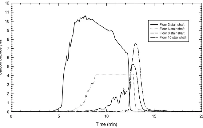
The temperature and CO2 measured in the stair shaft (Floors 2, 4, 6, 8 and 10) are shown in Figures 4 and 5, respectively and are used to show smoke movement in the stair shaft. The initial increase in the smoke parameters was a result of smoke flow through the leakage area between the corridor and the stair shaft. Once the door to the stair shaft was opened at 3 min, the smoke accumulation between the second and third floor was very rapid with the CO2 concentrations reaching 9% at 5 min.
There was a substantial time lag in the smoke reaching other floors. It required approximately 2 min after the stair shaft door was opened for the smoke to reach the sixth floor. There was minimal smoke at the tenth floor prior to activation of the PPV system at 10
min. The rapid increase in temperature and CO2 concentrations at the end of the test was as a result of the operation of the positive pressure ventilation system.
Bed Fire
The results for a test with the mattress and box spring using Scenario 1 are shown in Figures 6-8. The test compartment was on the seventh floor and the results are typical of those using Scenarios 1 and 2.
With the mattress fire, the fire development was much slower with the temperatures in the fire compartment reaching 200-250°C at 10 min after ignition (Figure 7). This resulted in a continuous increase in temperature in the corridor on the fire floor. The temperatures at the top of the door in the North corridor and the stairway door (Figure 8) were 180°C and 120°C, respectively at 10 min after ignition. At both locations, the temperature at lower heights reduced with the operation of the PPV system. However, there was an increase in the temperature near the ceiling. This was likely due to a higher burning rate as a result of the increase in ventilation air to the fire compartment as shown by the rise of the temperature in the test compartment during the later stages of the test.
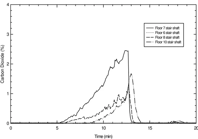
The smoke parameters in the stair shaft are shown in Figures 7 and 8. There was a continuous increase in the smoke at all levels throughout the test. However, it required approximately 3 min after the stairwell door was opened before the smoke reached the tenth floor. Also, the temperature increase on the tenth floor was significantly lower than on the fire floor (5°C versus 50°C).
Summer versus Winter Tests
The CO2 concentrations in stair shaft for a winter test with the exterior temperature at -20°C is shown in Figure 9 (an analyzer with a range of 0-4% was used on the sixth floor). In comparison with the warm weather test using the same test scenario (Figure 5), there was a more rapid increase in CO2 concentration due to stack effect. Also, with the winter test, there was an increase in temperatures in the fire compartment indicating improved ventilation. This resulted in a higher peak concentration of CO2 at the second floor (10.5% versus 9 %).
Stair Shaft Tenability
The sofa fire was a short duration (approximately 5 min) but very intense fire (Figure 2), which in an actual dwelling unit could have resulted in the ignition of other room contents. However, this limited fire did result in sufficient smoke accumulation in the stair shaft with smoke obscuration at the fourth floor reaching 0.8 OD/m (1-2 m visibility). This exceeds normal tenability criteria, which range from 0.05-0.5 OD/m depending on the application [9, 11]. The CO concentrations were limited to less than 0.01% which are significantly lower than the levels that would cause incapacitation with extended exposure (0.14-0.17% for 30 minute exposures [11]).
The bed fire was a slower growing fire, which reached its peak heat release rate at or shortly after the PPV venting was initiated. However, the smoke accumulation on the eight and tenth floor had reached or exceeded tenability limits (0.4 and 0.1 OD/m, respectively). As with the sofa fires, the CO concentration in the stair shaft was below levels, which could
cause incapacitation with extended exposure (0.03% and 0.01% at the seventh and tenth floors, respectively).
SMOKE MODEL
For the test conditions investigated, the smoke propagation up the stair shaft was relatively slow with significant time lag in the smoke reaching the higher floors. There was also considerable cooling of the smoke in the stair shaft (Figures 4 and 7). These results are consistent with those obtained by He and Beck for tests using a propane burner fire [7]. As a result, in the initial stages of a fire, significant smoke accumulation and untenable conditions can occur in the stair shaft at the fire floor with the upper levels remaining relatively smoke free. These observations are consistent with the conditions noted in real fire situations. As shown by He and Beck [7], it is unrealistic to model the smoke movement in the stair shaft using a simple two-zone model. Preliminary efforts to model the smoke movement produced by the sofa fire has been carried out using the network model, CONTAM [12] and a multi-compartment zone model, FIERAsmoke [13]. Experimental CO2 production and temperatures on the fire floor and in the stair shaft were used as input to CONTAM. The experimental heat release rate was used for FIERAsmoke. The calculated CO2
concentrations in the stair shaft are shown in Figure 10. The results from the
multi-compartment model compare well with the experimental data (The measured concentration was lower for the eight floor than the calculated level. However, there was problems with the analyzer used for this floor.)
The network model, CONTAM, over predicts the CO2 concentrations. Also, this model indicates a linear decrease in the CO2 concentrations with height compared with the more rapid decrease in concentration indicated by the experimental data. However, the model predictions were conservative and, considering the ability to handle large complex buildings, it can be a useful tool.
SUMMARY
This paper discusses the results of the initial stage of full-scale fire tests with typical residential furniture (sofas and beds) during which the smoke from the fires was allowed to fill the egress routes in a ten-storey test facility. The smoke movement in the egress routes was consistent for tests under similar conditions. However, as would be expected, smoke accumulation and movement in the stair shaft was quicker during the tests conducted in the winter than in the summer.
Shortly after ignition, the corridor on the fire floor was filled with smoke. After the stair shaft door was opened on the fire floor, the portion of the stair shaft immediately above the fire floor was quickly filled with smoke. However, the smoke movement up the stair shaft was relatively slow and there was considerable cooling of the smoke. As a result, there was little or no indication of smoke in the upper portion of the stair shaft prior to the operation of the ventilation system 10 min after the fire was started.
The smoke movement in the stair shaft cannot be modeled using a simple zone model. However, initial efforts using network and multi-compartment zone models indicated that
such models could be used. However, the network model does over predict the CO2 concentrations and the smoke movement in the stair shaft.
ACKNOWLEDGEMENTS
Canada Mortgage and Housing Corporation, Ottawa Fire Department, Tempest Technology Corporation and the Co-operators Insurance provided support for the project. The authors also acknowledge the support of G. Crampton, V. Fortington, C. McCartney, M. Ryan, B. Taber and M. Wright in the set-up and conducting the fire tests.
REFERENCES
1. Hall, J.R., U.S. High-Rise Fires: The Big Picture, NFPA Journal, March/April 1994, p. 47-53.
2. Webber, J.B., Report of the Public Inquiry into Fire Safety in Highrise Buildings, Ministry of the Solicitor General Ontario, Toronto, 1983.
3. Proulx, G. Ouellette, M.J. and Leroux, P. Study of the occupants’ behaviour during the Ambleside fire in Ottawa, Ontario on January 31, 1997, IR 771, National Research Council of Canada, Ottawa, 1998.
4. Proulx, G.P., Pineau, J., Latour, J.C. and Stewart, L., Study of the occupants’ behaviour during the 2 Forest Laneway fire in North York, Ontario, on January 6th 1995, IR 705, National Research Council of Canada, Ottawa, 1995.
5. Said, M.N.A, and MacDonald, R.A., An Evaluation of a Network Smoke Control Model, ASHRAE Transactions, Volume 97, 1991, p. 1.
6. Hokugo, A., Yung, D. and Hadjisophocleous, G.V., Experiments to Evaluate the NRCC Smoke Movement Model for Risk-Assessment, Fire Safety Science - Proceedings of the Fourth International Symposium, International Association for Fire Safety Science, Ottawa, 1995, p. 805-816.
7. He, Y. and Beck, V. Smoke Spread Experiment in a Multi-storey Building and Computer Modelling, Fire Safety Journal, Volume 28, 1997, p. 139-164.
8. Klote, J.H. and Milke, J.A., Design of Smoke Management Systems, American Society of Heating, Refrigerating and Air-Conditioning Engineers, Inc., Atlanta, GA, 1992. 9. Tamura, G.T., Smoke Movement & Control in High-rise Office Buildings, National Fire
Protection Association, Quincy, MA, 1994.
10. ASTM E1590, Fire Testing of Real Scale Mattresses, American Society for Testing and Materials, West Conshohocken, PA, 1995.
11. Purser, D., Toxicity Assessment of Combustion Products, The SFPE Handbook of Fire Protection Engineering, National Fire Protection Association, Quincy, MA, 1995.
12. Walton, G.N., CONTAM96: User Manual, NISTIR 6056, National Institute of Standards and Technology, Gaithersburg, MD, 1997.
13. Fu, Z. and Hadjisophocleous, G.V., A Two-Zone Fire Growth and Smoke Movement Model for Multi-Compartment Buildings, to be published.
Figure 1. Test arrangement on the fire floor. Time (min) 0 5 10 15 20 25 Heat Release Rat e (kW) 0 1000 2000 3000 Sofa Bed
Time (min) 0 5 10 15 20 25 Te m p er at ur e (°C) 0 100 200 300 400 500 600 700 800 900 1000
Fire compartment Floor 2
Stair shaft door (75 mm below top of door) Stair shaft door (482 mm below top of door) Stair shaft door (914 mm below top of door) Stair shaft door (1372 mm below top of door) Stair shaft door (1702 mm below top of door)
Figure 3. Temperatures on the fire floor for sofa test (Scenario 1 summer test).
Time (min) 0 5 10 15 20 Tem per ature (°C) 0 20 40 60 80 100 120
Floor 2 stair shaft Floor 4 stair shaft Floor 6 stair shaft Floor 8 stair shaft Floor 10 stair shaft
Time (min) 0 5 10 15 20 C a rbon Diox ide (%) 0 2 4 6 8 10
Floor 2 stair shaft Floor 6 stair shaft Floor 8 stair shaft Floor 10 stair shaft
Figure 5. CO2 concentrations in the stair shaft for sofa test (Scenario 1 summer test).
Time (min) 0 5 10 15 20 25 30 Te mpe rature (°C ) 0 100 200 300 400 500 600
Fire compartment Floor 7
Stair shaft door (400 mm below ceiling) Stair shaft door (800 mm below ceiling) Stair shaft door (1200 mm below ceiling) Stair shaft door (1700 mm below ceiling) Stair shaft door (2000 mm below ceiling)
Time (min) 0 5 10 15 20 Temperature (°C ) 0 10 20 30 40 50 60 70 80
Floor 6 stair shaft Floor 7 stair shaft Floor 8 stair shaft Floor 9 stair shaft Floor 10 stair shaft
Figure 7. Temperature in the stair shaft for bed test (Scenario 1 summer test).
Time (min) 0 5 10 15 20 Carb on Dioxide (%) 0 1 2 3 4
Floor 7 stair shaft Floor 6 stair shaft Floor 8 stair shaft Floor 10 stair shaft
Time (min) 0 5 10 15 20 C a rbon Diox ide (%) 0 1 2 3 4 5 6 7 8 9 10 11 12
Floor 2 stair shaft Floor 6 stair shaft Floor 8 stair shaft Floor 10 stair shaft
Figure 9. CO2 concentrations in the stair shaft for sofa test (Scenario 1 winter test).
0 2 4 6 8 10 12 14
2nd Floor 6th Floor 8th Floor 10th Floor
Floor Number
Concentration (mol/mol%)
Contam96 Experiment FIERAsmoke