Analysis of Large Deformation Offshore Geotechnical
Problems in Soft Clay
by
Zhandos Y. Orazalin
Bachelor's Degree, Karaganda State Technical University (2008)
Master of Science Degree, Massachusetts Institute of Technology (2012)
Submitted to the Department of Civil and Environmental Engineering
in partial fulfillment of the requirements for the degree of
Doctor of Philosophy in Civil and Environmental Engineering
at the
MASSACHUSETTS INSTITUTE OF TECHNOLOGY
June 2017
@
Massachusetts Institute of Technology 2017. All rights reserved.
Signature of Author ...
Signature redacted
Department of Civil and Environmental Engineering
May 17, 2017
Certified by ...
Signature redacted
Andrew J. Whittle
Edmund K. Turner Professor of Civil and Environmental Engineering
Accepted by ...
MASSACHUSETTS INSTITUTE OF TECHNOLOGYJUN 14 2017
Signature
V
Thesis Supervisor
redacted
Jesse H. Kroll
Professor of Civil and Environmental Engineering
Chair, Graduate Program Committee
Analysis of Large Deformation Offshore Geotechnical
Problems in Soft Clay
by
Zhandos Y. Orazalin
Submitted to the Department of Civil and Environmental Engineering on May 17, 2017, in partial fulfillment of the
requirements for the degree of
Doctor of Philosophy in Civil and Environmental Engineering
Abstract
Although finite element (FE) methods are well established for modeling geotech-nical problems in soil masses and soil-structure interaction, most prior research on large deformation problems has been limited to simplified assumptions on drainage conditions and constitutive behavior. This thesis investigates two large deformation problems in soft clay and proposes a methodology for performing coupled flow and deformation analyses with advanced effective stress models.
The first part of the research focuses on realistic 3-D finite element analyses (using AbaqusTM Standard) of a conductor (steel pipe pile) embedded within soft marine clay subjected to large lateral deformations caused by drift/drive-off of a drilling vessel. The proposed analyses use coupled pore pressure-displacement procedures together with the MIT-E3 soil model to represent the anisotropic, non-linear and inelastic effective stress-strain-strength properties of deepwater marine sediments with input parameters derived from a series of laboratory element tests performed on reconsti-tuted Gulf of Mexico (GoM) clay. The numerical predictions are evaluated through comparison with experimental results from centrifuge tests with a well-instrumented model conductor. The FE results accurately predict the measured bending moment distribution along the length of the conductor and the spread of plastic strains within the conductor itself. The study has also shown the effects of soil behavior on local pile-soil interactions, enabling simplified analyses using macro-elements. The FE re-sults have been used to calibrate input parameters for BWGG framework (Gerolymos & Gazetas, 2005), the Bouc-Wen (BW) model extended by Gerolymos and Gazetas
(GG), that simulates generalized hysteretic pile-soil interactions and allows for
degra-dation in soil resistance associated with geometric non-linearities.
The second application considers the effects of partial drainage for large deformation, quasi-static piezocone penetration in clay. The proposed axisymmetric FE analysis
the penetration resistance for a piezocone device using two elasto-plastic soil models
(MCC, MIT-E3) and the recent elasto-viscoplastic MIT-SR soil model (Yuan, 2016)
over a range of steady penetration velocities. The MCC predictions are in very good agreement with laboratory measurements of tip resistance and penetration pore pres-sures measured in centrifuge model tests in reconstituted kaolin. The results from more advanced soil models illustrate the impacts of anisotropic, rate dependent soil behavior on penetration tests in natural clays and are within the range of empirical measurements. The proposed analyses provide a complete framework that can now be used to investigate effects of partial drainage that occurs in piezocone tests for soils (such as silts) of intermediate permeability.
Thesis Supervisor: Andrew J. Whittle
Acknowledgments
I would like to express sincere gratitude to all people who supported me during my
studies and research at MIT. I am extremely grateful to Prof. Andrew Whittle, my research advisor, for his immense support over these years and continuous guidance in becoming an independent researcher. Prof. Whittle is an extraordinary mentor who is very patient with every student, always provides highly thoughtful advice with scientific rigor and encourages thinking big. I truly respect and appreciate him.
I am infinitely thankful to Prof. Herbert Einstein, my academic advisor, Prof. John
Germaine and Prof. Eduardo Kausel for their contributions and help with the work, as well as invaluable support and constant encouragement. I immensely appreciate the opportunity to know and to learn from these remarkable professors.
I would also like to acknowledge and thank Dr. Ed Clukey, Dr. Arash Zakeri, and Dr. Ryan Phillips for their support and contributions to this research.
My deep appreciation is expressed to my father, Prof. Yerbol Orazaly, and my mother,
Azhimova Shara who have always been the best parents in the world for me. I would like to mention my grandfather Ermek Orazalin, who always supported and encour-aged my desire for knowledge, and my beloved grandparents Sagyntai Azhimov and Saliya Azhimova.
I would like to thank all my mentors, colleagues and friends at MIT and beyond for
their support and encouragement. My sincere thankfulness and appreciation goes to Prof. Oral Buyukozturk, Dr. Lucy Jen, Prof. Jerome Connor, Prof. Adil Zhakulin, Prof. Askar Zhussupbekov, Prof. John Ochsendorf, Dr. Victor Nikitovich Popov, Prof. Ruben Juanes, Pat Dixon, Sayasat Nurbek, Prof. Markus Buehler, Angela Mickunas, Azamat Abdymomunov, Dr. Petr Aleksandrovich Kropachev, Prof. Juan
Dixon. Patty Glidden, Stephen Rudolph, Mira Parsons, Jeanette Marchocki, Sheila Fay, and many others.
I thank the entire MIT Kazakh Student Association, Anton Ermakov, Yixing, Vasso,
Nina, Ivo, Mauro, Eva, Despina, Ali, Jialiang, Vlad, Gonzalo, Davoud, Nikos, Amer, Sherif, Antonios, Omar, Steve, Bing, Wei, Chunwei, Amy, Bruno, Brendan, MJ, Aiden, Siavash, Adil, Sagyn, Kuandyk, Gleb and the rest of my longtime friends.
Finally, I would like to thank Madina, the love of my life, for her unconditional love and support.
Contents
1 Introduction
23
1.1 Problem Statement . . . . 23
1.2 Thesis Organization . . . . 26
2 Background 31 2.1 Introduction and Motivation . . . . 31
2.2 Overview of Large Deformation Numerical Methods for Geotechnical A pplication . . . . 35
2.2.1 Displacement-Based Finite Element Method . . . . 35
2.2.2 Eulerian and CEL (Coupled Eulerian Lagrangian) . . . . 35
2.2.3 ALE (Arbitrary Lagrangian Eulerian) . . . . 36
2.2.4 MPM (Material Point Method) . . . . 39
2.2.5 SPH (Smoothed Particle Hydrodynamics) . . . . 41
2.2.6 Remeshing and Interpolation Approach . . . . 43
2.3 Offshore Geotechnical Conditions and Selected Problems . . . . 44
2.3.1 Gulf of M exico Clay . . . . 44
2.3.2 Deepwater Conductors under Lateral Loads . . . . 48
2.3.3 Cone Penetration in Soft Clay . . . . 50
3 Methodology 77 3.1 Modeling of Conductor-Soil Interaction . . . . 77
3.1.3 Total Stress Analysis . . . . 81
3.1.4 Effective Stress Analysis . . . . 83
3.2 Proposed Large Deformation Analysis Procedure for Cone Penetration 84 3.2.1 Theoretical Preliminaries . . . . 86
3.2.2 Practical Implementation and Numerical Details . . . . 92
3.2.3 Evaluation and Validation . . . . 94
3.3 Advanced Constitutive Soil Models . . . . 95
3.3.1 MIT-E3 Soil Model . . . . 96
3.3.2 MIT-SR Soil Model . . . . 101
4 Numerical Simulation of Conductor-Soil Interaction Centrifuge Tests
and Validation
143
4.1 Centrifuge Model Tests . . . . 1434.1.1 Instrumentation . . . . 145
4.1.2 Prototype and Centrifuge Model Properties . . . . 145
4.2 Results of Centrifuge Model Tests . . . . 146
4.3 Laboratory Tests on GoM Clay Samples . . . . 147
4.4 Development of 3D Finite Element Models . . . . 147
4.4.1 Conductor Model Properties . . . . 147
4.4.2 Finite Element Modeling . . . . 147
4.5 Calibration of Advanced Effective Stress Model . . . . 148
4.6 Results of 3D Finite Element Analyses . . . . 150
5 Simplified Method for Conductor-Soil Interactions
187
5.1 Evaluation of p-y curves . . . . 1875.2 Large deformation geometric effects . . . . 188
5.3 Simplified methods for representing conductor-soil interaction . . . . 190
5.3.1 Implementation and calibration of a hysteresis model . . . . . 190
5.3.2 BWGG Model Input Parameters . . . . 192
5.3.3 Calibration of BWGG to 3D FE Models of Soil-Structure In-teraction . . . . 193
6 Numerical Modeling of Cone Penetration
6.1 Numerical Model of Cone Penetration ...
6.1.1 Geometry and Boundary Conditions . . . . 6.1.2 Contact Formulation . . . .
6.1.3 Mesh Sensitivity and Element Selection . . . . .
6.2 Simulation Results of Cone Penetration . . . .
6.2.1 MCC Analysis . . . . 6.2.2 MIT-SR Prediction . . . .
6.2.3 MIT-E3 Prediction . . . .
6.3 Comparison with Published Results . . . .
6.3.1 Material Point Method and Experimental Data
6.3.2 Strain Path Method and Field Data . . . .
7 Summary, Conclusions and Recommendations
7.1 Summary and Conclusions . . . .
7.1.1 Conductor-Soil Interaction . . . .
7.1.2 Piezocone Penetration . . . .
7.2 Recommendations for Future Work . . . .
219 . . . . 220 . . . . 220 . . . . 221 . . . . 223 . . . . 224 . . . . 225 . . . . 227 . . . . 228 . . . . 229 . . . . 229 . . . . 231 261 . . . . 261 . . . . 261 . . . . 263 . . . . 265
Bibliography
A Summary of Triaxial Test Results
B Numerical Settings and Procedures
C Source Code Listings
268
283 285 289
List of Figures
2-1 Schematic (Not to scale) of Conductor-Riser-Vessel System - Normal
Operation (a) vs. Loss of Vessel Position (b) . . . . 54
2-2 Lagrangian Approach (adapted from Banerjee) . . . . 55
2-3 Eulerian Approach (adapted from Banerjee) . . . . 55
2-4 Single ALE step (adapted from Ceccato and Simonini [20161) . . . . . 56
2-5 Computation scheme of MPM (Ceccato et al. [20161) . . . . 56
2-6 Finite element mesh and SPH particle distribution (SIMULIA [2016]) 57 2-7 SPH Kernel function (Wang et al. [2016]) . . . . 57
2-8 Undersea topography of the Gulf of Mexico (NOAA, Public Domain) 58 2-9 Location of deep-water sites in the Gulf of Mexico leading to an average set of soil properties referred to as "Average Gulf Clay" (Whittle and Sutabutr [20051) . . . . 58
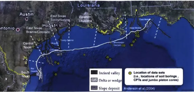
2-10 Location of Data Sets Reported by Cheon [2010] . . . . 59
2-11 Offshore conditions, waves and deepwater currents Gerwick [2007] . . 59
2-12 Water Content and Plasticity Chart of GoM Clay Compiled by Cheon [20101 ... ... 60
2-13 Submerged Unit Weight of Soil versus Depth of Gulf of Mexico Clay (C heon [2010]) . . . . 61
2-14 Undrained Shear Strength vs. Depth of GoM Clay Compiled by Cheon 120 101 . . . . 62
2-15 Reported Cone Factor used in Gulf of Mexico (Cheon [2010]) . . . . . 62
2-18 Triaxial Testing of GoM Clay - Effective Stress Paths (Sutabutr [19991) 64
2-19 Triaxial Testing of GoM Clay - Shear stress-strain response (Sutabutr
[1999]) . . . . 64 2-20 GoM clays in Ko-consolidated undrained direct simple shear tests (Sutabutr
[19991) . . . . 65
2-21 Dynamically Positioned Offshore Operation with Excursion Limits
-yellow, red, physical limits are not to scale (Chen et al. [20081) . . . . 66
2-22 Analysis of Laterally Loaded Pile Based on Beam theory (Pando [2013J) 67
2-23 Genesis of the P-Y curves (Reese et al. [1974], Matlock
119701)
. . . . 682-24 Plastic failure mechanism for laterally loaded conductor pile in plane strain (Houlsby & Randolph, 1984) . . . . 69
2-25 Comparison of computed p-y curves from FE models with data
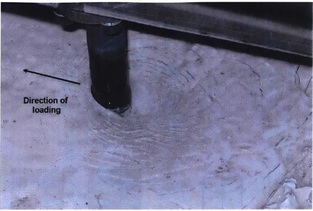
mea-sured in centrifuge model tests at 8 depths (Jeanjean, 2009) . . . . . 70 2-26 Observations of geometric non-linearities associated with surface
de-pression (and circumferential cracking) and mounding around model pile in centrifuge model test (Jeanjean, 2009) . . . . 71
2-27 Cone Penetrometer (Aubeny 119921, Levadoux 119801, Ceccato et al.
[20 161) . . . . 72
2-28 Geometry and discretization of the CPT simulation with MPM method
(Ceccato et al. 12016]) . . . . 73
2-29 Published MPM simulation - Tip Stress over normalized penetration
for different drainage conditions (Ceccato [2015]) . . . . 74
2-30 Effect of cone roughness on undrained cone factor (Ceccato 12015]) . . 75
2-31 Effect of drainage conditions on cone resistance and pore pressure
pa-rameters for piezocone in Kaolin simulated using MPM method and
MCC soil model (Ceccato et al. [20161) . . . . 75
2-32 Computed (MPM, Ceccato et al. 120161) cone resistance and measured
2-33 Comparison of pore pressure factor, Bq, between simulated (MPM,
Ceccato et al. [2016]) and measured (Centrifuge model, Schneider et al.
[2007]) piezocone tests in Kaolin . . . . 76
3-1 Reference Model Geometry of Replicate Analysis . . . . 112
3-2 Undrained shear strength profile (Templeton, 2009) . . . . 112
3-3 IHPP model parameters (Templeton, 2009) . . . . 113
3-4 Load-displacement response of Replicate Analysis . . . . 113
3-5 Replicate Analysis -"p-y" response . . . . 114
3-6 In-situ Stresses and Undrained Shear Strength Profiles for Typical Deepwater Gulf of Mexico Conditions . . . . 115
3-7 IHPP vs. EPP Soil Model Parameters for Initial Total Stress Analysis 115 3-8 Initial Total Stress Analysis - Load-Displacements at Mudline . . . . 116
3-9 Initial Total Stress Analysis - Lateral deformation profiles of elasto-plastic conductor from Base Case analyses with max. mudline offsets lm and 2m . . . . 116
3-10 Initial Total Stress Analysis - "p-y" response . . . . 117
3-11 Comparison of undrained load-deformation response at mudline using coupled finite elements with initial total stress analysis results . . . . 118
3-12 Comparison of p-y curves for undrained loading of conductor using coupled finite elements with initial total stress analysis results . . . . 118
3-13 p-y interaction curves from undrained analysis using MCC soil model 119 3-14 Effect of excess pore pressure dissipation in AGC (Holding Test) . . . 119
3-15 Excess pore pressures around conductor at depth of 10m, computed using MCC soil model for normally consolidated AGC at 6 h = 0.5m (H olding Test) . . . . 120
3-16 Finite Elements for 2D and 3D domains . . . . 121
3-17 Structured Quadrilateral mesh vs. Unstructured Triangular mesh . 121
3-20 Neighboring elements and nodes numbering (Hu and Randolph [1998a]) 122
3-21 A geometry with biased seeding . . . . 123
3-22 Scripting Interface commands and AbaqusTM Environment (SIMULIA [2016]) . . . . 124
3-23 General algorithm of the proposed procedure . . . . 125
3-24 Axisymmetric model of Cone Penetration Test . . . . 126
3-25 Abaqus Model with 60 Remeshing Steps and Contact Properties . . . 127
3-26 Proposed Procedure - Remeshing Example . . . . 128
3-27 Proposed Procedure - Step 1 - Deformed Mesh . . . . 129
3-28 Proposed Procedure - Step 2 - Geometry . . . . 129
3-29 Proposed Procedure - Step 3 - Locating Edges and Seeding . . . . 130
3-30 Proposed Procedure - Step 4 - Meshing . . . . 130
3-31 Proposed Procedure - Solution Mapping Example . . . . 131
3-32 Proposed Procedure - 3D Case . . . . 131
3-33 Initial Cone Penetration Analysis - Mesh . . . . 132
3-34 Initial Cone Penetration Analysis - Excess Pore Pressures . . . . 133
3-35 Initial Cone Penetration Analysis - Tip Reaction Force vs. Displacement 134 3-36 Initial Cone Penetration Analysis - Error Assessment . . . . 134
3-37 Initial Cone Penetration Analysis - Validation . . . . 135
3-38 Yield, Failure, and Load Surfaces used in MIT-E3 Model (Whittle and Kavvadas [1994]) . . . . 136
3-39 Hysteresis Model Used in MIT-E3 for Hydrostatic Compression: (a) Perfect Hysteresis; and (b) Hysteresis and Bounding Surface Plasticity (Whittle and Kavvadas [1994]) . . . . 136
3-40 Comparison of computed and measured undrained shear behavior -MCC and MIT-E3 soil models (Whittle and Kavvadas [1994]) . . . . 137
3-41 MIT-SR model surfaces in the triaxial stress space (Yuan [2016]) . 138
3-43 Comparison of MIT-SR predictions and measured data for results of
CKOUC and CKOUE tests on RBBC at a reference strain rate 6a =
0.5% /hr (Yuan [20161) . . . . 139
3-44 Effects of strain rate on the computed and measured undrained shear behavior of RBBC in CKoUC tests at OCR=1 (Yuan [2016]) . . . . . 140
3-45 Effects of strain rate on the computed and measured undrained shear behavior of RBBC in CKoUE tests at OCR=1 (Yuan 12016]) . . . . . 141
4-1 C-CORE centrifuge test schematic (prototype scale) . . . . 158
4-2 Centrifuge Test Tub (Presence of Sand Layers Marked in Green) . . . 159
4-3 Photos of Model Conductors and Instrumentation . . . . 159
4-4 C-CORE conductor tension test data . . . . 160
4-5 Undrained shear strength profiles . . . . 161
4-6 Measured bending moments from C-CORE centrifuge Model 1 . . . . 162
4-7 Measured bending moments from centrifuge Model 2 . . . . 163
4-8 Comparison of bending moments from cenrifuge models . . . . 164
4-9 Maximum elastic bending moments from centrifuge Models 1 and 2 . 164 4-10 Measured void ratio of Reconstituted GoM Clay . . . . 165
4-11 Measured 1-D consolidation behavior of Reconstituted GoM clay . . . 165
4-12 Measured triaxial shear behavior of RGoM Clay . . . . 166
4-13 Models for conductor material - Perfect vs. hardening metal plasticity 167 4-14 Yield Stress comparison for perfect vs. hardening metal plasticity . . 167
4-15 FE Model 1 and Conductor Model 1 . . . . 168
4-16 FE Model 2 and Conductor Model 2 . . . . 168
4-17 Example of different mesh sizes . . . . 169
4-18 M esh sensitivity studies . . . . 170
4-19 Schedule of tension loading at pinned connection above LMRP. Mea-sured load is approximated in FE model by a multi-linear fit . . . . . 171
4-21 Comparison of undrained triaxial shear behavior for Reconstituted GoM Clay with MIT-E3 predictions a) Effective stress paths, b) Shear stress-strain behavior . . . . 172
4-22 Effect of stress history on MIT-E3 predictions of undrained triaxial shear behavior (CKoUC and CKOUE tests) for reconstituted GoM clay 173 4-23 MIT-E3 predictions of undrained shear behavior Direct Simple Shear
mode (CKOUDSS tests) . . . . 173
4-24 Undrained shear strength profiles . . . . 174 4-25 Detail of undrained strength profile in upper part of centrifuge model 175
4-26 Base Case FE predictions of bending moments and conductor deflec-tions for centrifuge Model 1 . . . . 176
4-27 Details of plastic yielding in conductor from Base Case FE analysis 177
4-28 Contours of equivalent plastic strains in the conductor . . . . 177
4-29 Comparison of "apparent elastic bending moments" and actual bending moments computed from Base Case FE analysis . . . . 178
4-30 Comparison of predicted bending moments from Base Case FE analysis with measurements from centrifuge Model 1 . . . . 179
4-31 Comparison of computed bending moments for centrifuge Model 1 us-ing Base and Refined Case FE analyses . . . . 180
4-32 Comparison of predicted bending moments from Refined Case FE analy-sis with measurements from centrifuge Model 1 . . . . 181
4-33 The effect of refinements in modeling plasticity of the steel conductor (EPP vs IHPP) on the computed bending moments for the Refined Case (M IT-E3) . . . . 182
4-34 The effect of refinements in modeling plasticity of the steel conductor (EPP vs IHPP) on the computed apparent elastic bending moments for the Refined Case (MIT-E3) . . . . 183
4-35 Comparison of predicted bending moments from Refined Case FEA using IHPP conductor with measurements from centrifuge Model 1 . 184
4-36 Simulation of conductor response for large pushover deformations using EPP FE analysis . . . . 185
4-37 The effect of refinements in modeling plasticity of the steel conductor (EPP vs IHPP) on the computed bending moments and deformations of the conductor response for large pushover deformations using EPP
FE analysis . . . . 186
5-1 Comparison of computed p-y curves from Base Case and Refined FE analyses showing effect of stress history profile on local conductor-soil interactions . . . . 198 5-2 Effect of soil model on computed conductor-soil interactions from
Re-fined (MIT-E3) and EPP FE analyses . . . . 199 5-3 Np values from Refined (MIT-E3) Analysis . . . . 200
5-4 Np values from FE analysis with EPP soil model . . . . 201
5-5 Local conductor soil interaction for large pushover events (max. 6h = 5.9m)
computed from EPP FE analysis of centrifuge Model . . . . 202
5-6 Simulation of local conductor-soil response for reversal of pushover (with maximum h =2.3m) using Refined Case FE model . . . . 203 5-7 Simulation of local conductor-soil response for reversal of pushover
(with maximum h =2.3m) using EPP analysis . . . . 204
5-8 BWGG Model parameters for monotonic loading . . . . 205 5-9 BWGG parameters for cyclic loading . . . . 206
5-10 Monotonic loading - Comparison of BWGG model with 3D FE
simu-lations using EPP model . . . . 207
5-11 Monotonic loading - Comparison of BWGG model with 3D FE simu-lations using MIT-E3 model (Refined case) . . . . 208
5-12 Large deformation conductor-soil interaction in cyclic loading from 3D
FE analysis using EPP model . . . . 209
5-14 BWGG model of normalized cyclic conductor-soil interactions based on simulations using EPP soil model . . . . 211
5-15 Comparison of BWGG and 3D FE models of normalized local
conductor-soil interactions in cyclic loading for EPP conductor-soil model . . . . 212
5-16 Computed local conductor-soil interactions in cyclic loading from 3D FE analysis using MIT-E3 Refined Case analysis . . . . 213 5-17 Normalized conductor-soil interactions in cyclic loading from 3D FE
analysis using MIT-E3 Refined Case analysis . . . . 214
5-18 BWGG model of normalized cyclic conductor-soil interactions based
on simulations using MIT-E3 Refined Case analysis . . . . 215 5-19 Comparison of BWGG and 3D FE models of normalized local
conductor-soil interactions in cyclic loading for MIT-E3 Refined Case . . . . 216 5-20 Developed calibration tool "ModelTest" - Main Interface . . . . 217 5-21 Example output of "ModelTest" program . . . . 217 5-22 Developed tool for representing simplified conductor-soil interactions
-C alibration . . . . 218 5-23 Developed tool for representing simplified conductor-soil interactions
-M ain O utput . . . . 218
6-1 Location used to interpret predictions of piezocone pore pressures . . 236 6-2 Base Case Model with Coarse Mesh . . . . 237 6-3 Base Case Model with Fine Mesh . . . . 237
6-4 Node-to-surface contact discretization (SIMULIA [20161) . . . . 238 6-5 Smoothing master surfaces for finite-sliding node-to-surface contact
formulation (SIMULIA [20161) . . . . 238 6-6 Contact surfaces and adjustment zone (SIMULIA [2016]) . . . . 238 6-7 The results obtained from fine and coarse meshes using various
ele-m ents . . . . 239 6-8 Summary of piezocone tip resistance at selected steady penetration
6-9 MCC soil model (BBC) analyses - net tip resistance for various pene-tration rates . . . . 240
6-10 Base Case MCC Analysis - Excess pore pressures at depth of 6R (11cm) 241
6-11 Evolution of excess pore pressures at a fixed point 5 cm below the
surface . . . . 241
6-12 Base Case MCC Analysis -Excess pore pressure profiles at Penetration
depth of 6R (11cm ) . . . . 242
6-13 Deformed mesh configuration after deep penetration using MCC soil
model (minimized distortion) . . . . 243 6-14 Base Case MCC Analysis - Normalized radial stress
( )
contours . . 244qVO
6-15 Base Case MCC Analysis - Normalized mean stress (' "-) contours . 244 vO
6-16 Base Case MCC Analysis - Cylindrical expansion shear stress
contours . . . . 245
6-17 Base Case MCC Analysis - Normalized shear stress (4-) contours . . 245
6-18 Base Case MCC Analysis - Effect of OCR. on Cone Resistance . . . . 246
6-19 Simulations of undrained penetration+ using MIT-SR soil model (BBC)247
6-20 MIT-SR., MCC analyses - net tip resistance for various penetration rates247
6-21 MIT-SR Analysis - Excess pore pressures at Penetration depth of 6R 248
6-22 MIT-SR Analysis - Evolution of excess pore pressures at a fixed point
4.5 cm below the surface . . . . 248
6-23 MIT-SR. Analysis - Excess pore pressure profile for default penetration
rate (v = 2 cm/s) at penetration depth of 6R (11cm) . . . . 249 6-24 Mesh configuration obtained after deep penetration using MIT-SR soil
model (minimized distortion) . . . . 250
6-25 MIT-SR Analysis - Normalized radial stress (1-) contours . . . . 251
0vO
6-26 MIT-SR Analysis - Normalized mean stress ("yran) contours . . . . . 251
ovo
6-27 MIT-SR Analysis - Cylindrical expansion shear stress
("
0) contours2526-28 MIT-SR Analysis - Normalized shear stress (4-) contours . . . . 252
avO
6-31 MIT-E3 Analysis - Excess pore pressures at Penetration depth of 8.3R (15cm ) at OCR=1.0 . . . . 254
6-32 MIT-E3 Analysis - Evolution of excess pore pressure at a fixed point
5 cm below the surface . . . . 254
6-33 MIT-E3 Analysis - Excess pore pressure profile for default penetration rate (v = 2 cm/s) at Penetration depth of 6R (12cm) . . . . 255
6-34 Deformed mesh quality after deep penetration using MIT-E3 soil model 256
6-35 Replicate MCC (Kaolin) Analysis - Summary of penetration analyses for various drainage conditions . . . . 257 6-36 MCC Kaolin Analysis - Evolution of excess pore pressures . . . . 257 6-37 MCC Kaolin Analysis - Excess pore pressure profiles at Penetration
depth of 6R (11cm ) . . . . 258 6-38 Comparison with MPM simulations (Ceccato
12015])
and MeasuredData (Schneider et al.
12007])
. . . .
259
6-39 FEM Predictions vs. SPM Results for Steady State Penetration (Aubeny [1992]) . . . . 260
6-40 FEM Predictions vs. Measured Piezocone Data from South Boston (Ladd [1990], Aubeny [1992], Ladd et al. [1999]) . . . . 260
List of Tables
3.1 Input parameters for Average Gulf Clay using MCC soil model (Whittle
and Sutabutr [2005]) . . . . 107
3.2 Transformed variables used in MIT soil models (Whittle and Kavvadas [1994], Yuan [2016]) . . . . 108
3.3 MIT-E3 Soil Model Input Parameters (Whittle [1993b]) . . . . 109
3.4 MIT-SR Soil Model Input Parameters (Yuan [2016]) . . . . 110
3.5 Bearing Capacity Factors - Replicate Analysis vs. Templeton [2009] . 111 4.1 Centrifuge Test Instrumentation . . . . 153
4.2 Conductor properties . . . . 154
4.3 MIT-E3 Soil Model Input Parameters for C-CORE GoM Calibration 155 4.4 Summary of computed engineering properties for Average Gulf Clay and reconstituted NC Gulf of Mexico clay using MIT-E3 soil model . 156 4.5 Effect of IHPP conductor on actual bending moments with EPP model (Full Range Case) . . . . 156
4.6 Effect of IHPP conductor on actual bending moments with MIT-E3 model (Refined Case) . . . . 157
4.7 Effect of IHPP conductor on apparent elastic bending moments with MIT-E3 model (Refined Case) . . . . 157
5.1 The list of the general BWGG model input parameters . . . . 197
5.2 Calibrated BWGG parameters - Monotonic Loading . . . . 197
6.1 Input parameters for MCC soil model . . . . 232 6.2 MIT-E3 Soil Model Input Parameters for BBC (Hashash [1992]) . . . 233 6.3 MIT-SR Soil Model Input Parameters for RBBC (Yuan [2016]) . . . . 234 6.4 Strain Path Method Predictions for Ko-consolidated BBC (Aubeny
[1992]) . . . . 235 6.5 Predictions using large deformation FEM for KO-consolidated BBC 235
A. 1 Summary of Performed Triaxial Undrained Tests on RGoM Clay . . . 283
B. 1 Project files for cone penetration analysis in AbaqusTM Standard . . . 285
B.2 Description of procedures as implemented in Python code for auto-mated remeshing and interpolation analysis . . . . 286
Chapter 1
Introduction
1.1
Problem Statement
The constantly increasing worldwide energy demand has led to offshore hydrocar-bon exploration and production. The offshore oil and gas development has expanded into the water depths greater than 1000 meters since the 1990s. These deepwater environments required different considerations for reliability and the development of novel foundation systems that facilitated the mooring of floating production and ex-ploration platforms. These advances necessitated considerable investment in offshore engineering research and the field of offshore geotechnics (Randolph and Gourvenec [2011]). Offshore geotechnical considerations are important in all aspects of plan-ning, desigplan-ning, and operating of offshore facilities. The consequences of a failure for these facilities can be severe and the costs associated with the remediation efforts are very large. Geotechnical engineers must deal not only with design concerns for off-shore foundations under various loading conditions (McCarron [20111), but also take into account the complex behavior of soils (non-linear, inelastic, anisotropic and time dependent behavior) (Mitchell et al. 12005]), uncertainties associated with geologic materials (Einstein 12003]) and the challenges related to offshore site investigations (Randolph et al. [20051).
in-pipe, is installed deep into the seabed to provide the stable structural foundation for the oil well. These conductor pipes connected to the floating vessels are subject to large lateral loads produced by waves and winds associated with offshore storms and other factors. As a result, a geotechnical engineering problem of an offshore founda-tion or a conductor pipe subjected to lateral loading involves the interacfounda-tion of soil and conductor. The ability to make reasonable estimates of the behavior of laterally loaded conductors is an important design consideration. Complex loading conditions and the necessity to accurately evaluate conductor-soil interaction required the fur-ther development of numerical capabilities to reliable model the lateral responses of offshore structures. The comprehensive physical model tests of laterally loaded con-ductors are required to evaluate the performance of conductor-soil interaction and to validate more advanced numerical modeling capabilities. Currently, most finite element analyses of laterally loaded piles or conductors focus on the lateral displace-ments within 0.1-0.2 of pile/conductor diameters and are often limited to the simple isotropic constitutive soil models with the total stress approach (in which the soil is modeled as a single-phase material).
The most prominent example of large deformation geotechnical problems, how-ever, is the soil penetration problem that relates to the mechanics of penetration in porous media (with the applications ranging from penetrometers, to the performance of driven piles, and pile installation effects). The analysis of soil penetration repre-sents a very challenging class of geotechnical problems due to the high gradients of the field variables (stresses, strains, pore pressures, etc.) around the penetrometer, the large deformations and strains in the soil, the complex constitutive behavior of soils, and the non-linear penetrometer-soil interface characteristics. The cone penetration test (CPT) is currently the most performed in-situ test during offshore geotechnical investigations (Randolph and Gourvenec [2011]). The interpretation of engineering properties of soils is based on theoretical and experimental analyses of the testing method. The reliable numerical modeling of this test will also contribute to the development of meaningful correlations between engineering properties of soils and in-situ measurements. Although there has been some modest progress in the analysis
of penetration problems using various numerical methods with mostly simple consti-tutive models, the reliable modeling of large deformation geotechnical problems using advanced effective stress soil models remains to be a great challenge.
The overall goal of this thesis is to study large deformation offshore geotechnical problems with advanced effective stress soil models. The current research undertakes two main tasks: 1) the development of reliable models of conductor-soil interaction under large lateral loads using realistic modeling of constitutive soil behavior and taking advantage of extensive prior research at MIT on the Gulf of Mexico (GoM) Clay; 2) the development of numerical capabilities to perform extremely large defor-mation analyses using advanced effective stress soil models. These capabilities are demonstrated through the analysis of large deformation offshore cone penetration in soft clay considering the partial drainage, stress history, and penetration rate effects.
The first part of this work involves the development, validation and refinement of
3D Finite Element (FE) models of conductor-soil interactions in soft clay that
simu-late the loading conditions associated with offshore drift/drive-off loading events (that cause large lateral loads and tension). The analyses use the advanced effective stress soil model MIT-E3 (Whittle and Kavvadas [1994]) and some simple isotropic EPP (elastic-perfectly plastic) and IHPP (isotropic hardening) soil models. The MIT-E3 soil model provides a more comprehensive framework for characterizing the non-linear, hysteretic and anisotropic stress-strain-strength properties of soft clays and is capable of achieving reasonable predictions of cyclic load response (e.g., accumulation of plas-tic strains) (Whittle and Kavvadas [19941). The simulations results were validated through comparisons with the results of physical model tests carried out in a large geotechnical centrifuge facility. This study provided some useful insights into the be-havior of offshore conductor subjected to large lateral loads under tension. The effects of the soil models and the elasto-plastic properties of the conductor are considered and compared. The location of the plastic hinge developed due to large bending is de-termined. The load-unload-reload cycle was also considered and a simplified method to represent conductor-soil interaction was proposed.
to analyze extremely large deformations related to the mechanics of penetration us-ing advanced effective stress soil models. The method is based on the automated remeshing and solution mapping technique (Hu and Randolph [1998a]). The cone penetration test (CPT) in soft clay was modeled with several soil models including the MCC (Modified Cam Clay) (Roscoe and Burland [1968]), MIT-E3 (Whittle and Kavvadas [1994]) and MIT-SR (Yuan [2016]) soil models. The predictions of cone penetration are evaluated through comparisons with the published results (Aubeny
[1992], Ladd et al. [1999], Schneider et al. [2007], Ceccato et al. [2016]) that used
various numerical methods (MPM, Strain Path Method) and the experimental (field and laboratory) measurements. The realistic soil behavior, effect of stress history and the considerations of partially drained conditions were taken into account in the developed Finite Element simulations of piezocone penetration. In addition, it is well-known that the undrained shear response of clays is dependent on the shear strain rate, but this is not usually considered directly in most available soil models that have been used in the previously published penetration analyses. In this study, the realistic modeling of penetration rate effects was achieved using a newly devel-oped elasto-viscoplastic MIT-SR model capable of modeling rate-dependent behavior of clays. The methodology to perform large deformation geotechnical analyses using advanced effective stress soil models is developed, discussed and presented in this thesis.
1.2
Thesis Organization
The thesis chapters are organized in the following way:
Chapter 2 describes the background information. Initially, it presents the intro-duction and motivation for this research. Then, it provides an overview of existing large deformation numerical analysis methods applicable to geotechnical engineer-ing problems. The main Finite Element Method (FEM) formulations are introduced (Lagrangian and Eulerian formulations). The most relevant large deformation gen-eral numerical analysis methods such as ALE (Arbitrary Lagrangian Eulerian), CEL
(Coupled Eulerian Lagrangian), MPM (Material Point Method) and SPH (Smoothed Particle Hydrodynamics) are briefly presented and summarized. After that, the adap-tivity techniques are discussed including the so-called Remeshing and Interpolation Technique with Small Strain (RITSS) that was used as a basis for the proposed methodology. Next, offshore geotechnical conditions are described along with the previously published research on deepwater conductors under lateral loads and cone penetration problems in soft clay. The conventional analysis methods of laterally loaded piles using "p-y" curves and the overview of cone penetration basics are also covered.
Chapter 3 presents the proposed methodology for large deformation numerical analyses of geotechnical problems. The chapter starts with the description of model-ing methodology for conductor-soil interaction. The initial base case 3D Finite Ele-ment Model developEle-ment is described. The methodology for obtaining soil reactions and p-y curves is presented. Then, the comparison with the previously published nu-merical results is shown using the total stress analysis. Next, the total stress analysis methodology is compared with the effective stress analysis approach. The theoretical preliminaries and implementation details of the proposed large deformation analy-sis methodology are presented. Debugging strategies, validation and practical usage evaluation are also provided. Finally, the advanced effective stress constitutive soil models are described providing a brief overview of MIT-E3 and MIT-SR soil models used in the subsequent numerical simulations.
Chapter 4 provides the results of numerical simulations for conductor-soil inter-action centrifuge model tests and results validation. First, the centrifuge model tests are described. The instrumentation and model properties are presented. The Resed-imented Gulf of Mexico Clay (RGoM) soil samples obtained after the centrifuge tests were delivered to MIT Soil Mechanics Laboratory and tested in Ko-consolidated tri-axial compression and extension undrained shear tests with appropriate repeatibility. The results of these tests are presented, and the calibration of the advanced effec-tive stress soil model MIT-E3 associated with Average Gulf Clay (AGC) parameters
Element Model of the test conductors subjected to the prescribed tension loads and lateral displacements is described. The assumed properties of the conductor material and used undrained shear strength profiles are explained. The analysis results are then compared to the measured data obtained from the centrifuge model tests. The discussed results include the bending moments, lateral deflection profiles, conductor rotations and the plastic strains in the conductor to determine the location of the hinge due to excessive bending. The mesh sensitivity studies are also presented.
Chapter 5 presents the simplified methods for representing conductor-soil interac-tions. This chapter describes the evaluation of p-y curves associated with the lateral loading of the conductor. The back-bone curves for monotonic loading are obtained for the analyses using EPP and MIT-E3 soil models. The geometric effects and other interaction considerations are discussed. A simplified model based on BWGG frame-work is presented. The calibration of a hysteresis (Bouc-Wen) model is shown, and the input parameters are presented for monotonic and cyclic loading conditions. A basic set of 4 input constants are needed to achieve reasonable representation of conductor-soil response in monotonic lateral loading, including softening effects associated with geometric non-linearities. The results obtained from the simplified methods are com-pared with the 3D Finite Element Analysis results for monotonic and cyclic loading conditions.
Chapter 6 provides the numerical analysis of cone penetration testing in soft clays. This chapter provides an overview of cone penetration testing and modeling aspects of the problem. The development of axisymmetric numerical models is described. Large deformation effective stress analyses are conducted using the proposed methodology described in Chapter 3. The results of the analyses using the three effective stress soil soil models are presented. First, the obtained results using MCC soil model considering the effects of partial drainage are compared with the most recently pub-lished work on modeling the cone penetration test using the two-phase Material Point Method (MPM). Then, the results are compared with the measured data. Next, the analyses using more realistic soil models that take into account complex soil behavior and penetration rate effects are presented considering the effect of stress history. The
MIT-E3 and MIT-SR simulation results are compared with the measured field data (Ladd et al. [1999]) and the steady state analytical solutions obtained from the Strain Path Method (Baligh and Levadoux [1986], Aubeny
[1992]).
Chapter 7 summarizes the work with the main conclusions and presents the the recommendations for future research. The obtained insights and useful contributions of the work are outlined.
The summary results of the laboratory tests conducted on the samples of Resedi-mented Gulf of Mexico Clay are presented in the Appendix A. The numerical details and procedures for large deformation effective stress analyses using axisynmietric and
3D Finite Element models are summarized in Appendix B. Appendix C contains the
Chapter 2
Background
This research was initially motivated by a practical offshore engineering project involving large lateral deformations of a conductor pipe in soft clay and the opportu-nity to validate the three-dimensional numerical predictions against measured data from a sophisticated centrifuge model test. The study was then extended to investi-gate large deformation penetration problems. This chapter presents the background information on the subject and a brief overview of the existing numerical analysis methods to discuss the rationale behind the proposed methodology presented in the next chapter.
2.1
Introduction and Motivation
Deepwater well drilling projects for oil and natural gas are complex endeavors with a great number of challenges and risks (Randolph et al. [2005]). The oil and gas reserves are located deep within the seabed. An offshore borehole or oil well is drilled
by a floating vessel that is dynamically positioned (DP) at the site using a
satel-lite GPS (Global Positioning System) signal. The DP system aims to automatically maintain vessel's position by means of the vessel's own propellers (thrusters) prevent-ing it from driftprevent-ing due to the wind, waves, or sea currents. The upper section of the borehole/wellbore is stabilized by a conductor, a large diameter pipe. A blowout
preventer stack comprises the LMRP (lower marine riser package) and blowout pre-venter (BOP) that can be used to control and monitor or seal oil and gas wells. The drilling vessel floating on the water surface is connected to the seafloor through the blowout preventer via a marine riser. This slender pipe provides a conduit to provide a temporary extension of a subsea oil well to a surface drilling facility (Figure 2-1). The riser is held under tension to maintain stability.
Due to current, wind and wave loading, or other unfavorable conditions such as failure of the DP system the vessel may drift off-station causing failure in the riser-conductor-soil system either above or below the mudline (Figure 2-la). During emergency drift-off situations, the riser should be immediately disconnected from the conductor and the well has to be sealed within the blowout preventer. One of the main risks during deepwater drilling operations is the failure of the conductor system below the blowout preventer (Figure 2-1b). This is the most unfavorable and catastrophic situation that can lead to uncontrolled release of oil and gas from the wellbore.
Prior simulations of DP system failures (Josefsson and Dincal [2014]) have included independent analyses of the quasi-static loading conditions during the drift/drive-off process and the dynamic response of the system following parting of the riser (recoil and collapse through the water column). For deepwater conditions (1500-1800 m), the results show that the initial yield occurs in the conductor (typically at depths up to 15m below mudline) when the drilling vessel is offset at 8-10', with mudline displace-ments of 3-4.6m (i.e., d/D = 3-6, for conductors with outside diameter, 0.71-0.91m). The post-parting of the riser generates large cyclic bending moments in the conductor and can cause significant permanent deviations from the vertical.
The main goal of this research is to develop and validate numerical models of conductor-soil interactions that can be integrated within a comprehensive analysis framework of the riser-wellhead system and, hence, enable oil and gas engineers to evaluate well integrity for uncontrolled drift-off or drive-off loading conditions. The work carried out during this research has involved the development, validation and refinement of 3D Finite Element (FE) models of conductor-soil interaction that repre-sent: 1) the large deformation conditions associated with drift/drive-off load events;
and 2) the non-linear, inelastic and anisotropic constitutive behavior of marine sed-iments typically encountered in the Gulf of Mexico. The former is addressed by using AbaqusTM Standard solver with coupled pore pressure-stress elements and
tak-ing into account geometric non-linearity (for extreme deformations associated with penetration mechanics problems, a new procedure for remeshing and interpolation is implemented). The latter is achieved by comparing the results for a generalized ef-fective stress soil model, MIT-E3 (Whittle and Kavvadas
11994]),
which is integrated within the commercial AbaqusTM Standard Finite Element program through a UserMaterial (UMAT) interface. Prior studies (Whittle and Sutabutr 12005]) have shown that the MIT-E3 model is capable of describing the anisotropic, non-linear and inelas-tic effective stress-strain-strength properties of deepwater sediments from the Gulf of Mexico (GoM).
The numerical predictions are evaluated through comparisons with data from two physical model tests performed in a 5.5m radius beam centrifuge at C-CORE (Canadian research and development corporation) within a testbed of reconstituted GoM clay. These tests measured bending strains in the model conductor pipe over an embedded depth of 60m (prototype scale) associated with simulated riser drift-off and separation events. Numerical predictions of the centrifuge tests are conducted by independently calibrating input parameters for the MIT-E3 using a suite of elemental laboratory tests (ID consolidation and undrained triaxial shear tests) on specimens of the reconstituted GoM clay'. Predictions of conductor-soil interaction are then based on selection of a stress history profile for the centrifuge testbed to achieve close matching with the measured undrained shear strength profile.
Substantial computational efforts are required to conduct 3D FE simulations of conductor-soil interactions for the large lateral deformations expected in drift-off events. The representation of these interactions as a component in the simulation of the overall riser-wellhead system can be accomplished more efficiently through simplified local interaction models (p-y representation). We have implemented the BWGG generalized p-y model originally developed by Gerolymos and Gazetas [2005b]
to describe pile-soil interactions in seismic loading events. Input parameters for the BWGG model are then calibrated from the 3D FE simulations.
The main motivation to extend the current research into the analysis of deep soil penetration was to demonstrate the developed numerical capabilities (automatic remeshing and interpolation) on a large deformation axisynimetric problem that is very important within geotechnical engineering practice. Historically, the approxi-mate solutions methods for the analysis of this problem in saturated clays included bearing capacity, cavity expansion and the strain path methods. Previous studies have shown the limitations of the approximate cavity expansion solutions for deep penetration problems (Levadoux [1980], Baligh and Levadoux [1986]). Strain path analyses provide an approximate solution for undrained steady state penetration. However, there was a need in a more realistic solutions that could help to improve rational approaches to in-situ test interpretation (Aubeny [1992]). Large deformation
FE analyses are required to introduce correct initial conditions and to simulate a
displacement of at least several times of the diameter of the cone to give a realistic build up of the shaft pressure (van den Berg [1994]). These analyses must address the large gradients of solution variables (stresses, deformations, pore pressures) and to approximate the steady state of the cone tip penetration. Currently, most full finite element analysis solutions of deep penetration in clay are limited to either total stress formulations (not taking into account the pore pressures) or simple isotropic constitutive models. Even though simple soil models provide a useful insight into the mechanics of deep penetration in clays, more comprehensive constitutive soil models are required for reliable predictions of pore pressures and effective stresses during and after the test procedures. Advanced effective stress soil models including a newly developed advanced elasto-viscoplastic model capable of capturing rate effects (Yuan
[2016]) are used in the current study of large deformation deep penetration problems.
The proposed methodology can be readily extended to layered soil profiles and various drainage conditions.
2.2
Overview of Large Deformation Numerical Methods
for Geotechnical Application
In this thesis, we focus on the continuum approach to representing the soil in nu-merical models. This section presents a brief description of the traditional Lagrangian and Eulerian formulations within the Finite Element Method and introduces some of the practical methods and techniques for large deformation numerical analyses with regard to the geotechnical application.
2.2.1
Displacement-Based Finite Element Method
In the traditional displacement-based finite element method formulation (also known as the Lagrangian finite element method), the material associated with the mesh remains associated with it throughout the analysis (i.e. the mesh and the ma-terial are coupled). The mama-terial moves with mesh deformations, and the mama-terial cannot flow across the boundaries of mesh elements. The nodes at the boundary of the material remain at the boundary during the analysis (Figure 2-2). The Gauss points also move with the material allowing the constitutive equations to be evalu-ated at the same material points. The interface between different materials and the boundary conditions are easily tracked due to a well-defined free surface of the ma-terial boundaries. For large deformations associated with soil penetration analysis, mesh distortion problems arise when the material is severely deformed . As a result, one of the main drawbacks of the conventional Lagrangian finite element method is the limitation in modeling very large deformations associated with mesh distortion.
2.2.2
Eulerian and CEL (Coupled Eulerian Lagrangian)
In Eulerian formulation, the mesh is fixed in space and material flows through the mesh. Eulerian formulation is commonly used for fluid mechanics problems and is not susceptible to mesh distortion problem due to large deformations. The Eulerian
boundaries and creates a space in which the material is free to move and deform (Figure 2-3). Any Eulerian material that moves outside the Eulerian mesh is not con-sidered in the simulation. Eulerian elements may be partially or completely empty of the material. It becomes challenging to track the material boundaries as the material deforms within a fixed mesh. In the Eulerian description, the mesh is decoupled from the material. This introduces numerical difficulties with history-dependent materials (such as elasto-plastic soils) as convective terms appear in the Eulerian FE formula-tion. Effectively, large distortions of the material are handled at the expense of the resolution in flow details (Donea et al. [2004]).
It is possible to have Eulerian and Lagrangian meshes interacting with each other within the same analysis using contact algorithms. This type of numerical analy-sis method is referred to as the Coupled Eulerian Lagrangian (CEL) analyanaly-sis and has been implemented in the commercial finite element software AbaqusTM Explicit (SIMULIA
[2016]).
CEL is typically used to model the interactions between a solidbody and a yielding or fluid material, such as a Lagrangian cone penetrating through Eulerian soil or an Eulerian gas inflating a Lagrangian airbag. For geotechnical en-gineering purposes, the CEL method has only been applied to analyze various large deformation problems in fully drained and fully undrained conditions (Qiu et al. [2011]). This method has yet to be extended to effective stress analyses with mixed deformation and pore pressure elements in AbaqusTM (SIMULIA [20161).
2.2.3
ALE (Arbitrary Lagrangian Eulerian)
The Arbitrary Lagrangian Eulerian (ALE) is a broad class of FE formulations that combine the advantages of Lagrangian and Eulerian formulations. In the ALE approach, the nodes of the mesh can move with the material (normal Lagrangian mode) or can be held fixed (Eulerian manner), or can be moved in some arbitrarily specified way to give a continuous mesh-update capability. As a result, the pure Lagrangian and pure Eulerian formulations can be regarded as a special cases of the ALE aproach. Larger distortions of the material can be handled than would be possible in a purely Lagrangian method with more resolution than that is afforded by
a purely Eulerian approach due to the freedom in moving the computational mesh in an ALE method (Donea et al. [2004]). The convective terms enter the governing ALE equations just as in the Eulerian formulation. The treatment of these terms plays a crucial role in the numerical implementation, especially for complex path-dependent constitutive models (Savidis et al.
[2008]).
There are several variations of the ALE approach depending on different advection schemes and remapping strategies including Single-Material Arbitrary Lagrangian-Eulerian (SMALE), Multi-Material Arbitrary Lagrangian-Lagrangian-Eulerian (MMALE) and Efficient Arbitrary Lagrangian-Eulerian (EALE), etc. Nevertheless, the key idea of
ALE method is that the computational mesh can move independently (arbitrarily) of
the material. Therefore, the motion of the material and of the mesh must be defined. The remapping of the solution variables is performed using the basic ALE kinematic formula (Hughes et al. [1981], Nazem et al. [20061):
=f+ (vi
- V)
(2.1)
where
f
is an arbitrary function, vi is the material velocity, vr is the mesh velocity,j
denotes the time derivative off
with respect to the mesh coordinates, and _ represents the time derivative of f with respect to the material coordinates. The term (vj - v,) is the convective velocity.In the ALE method, the discretized governing equation can be written in a general form as follows (Gadala and Wang [1998], Nazem et al. [20061):
[Ks]
{AUg}
+ [Kiy]
{AUj }
=
{Rj}
-
{F}
(2.2)
where K' is the stiffness matrix related to material displacement vector; K' is the stiffness matrix related to the mesh displacement vector; U is the material displacement vector; U' is the mesh displacement vector; R is the external load vector; and F is the internal force vector. The material and the mesh displacements are two unknowns at each degree of freedom. Since the mesh displacements are
doubled. Therefore, supplementary equations are required to solve the equilibrium equation.
Benson [1989] proposed a split of the ALE operator into a Lagrangian step and an Eulerian step to decouple mesh and material displacements: i) the system of governing equations is solved in the Largangian step using implicit or explicit finite element procedures; and ii) the Lagrangian mesh is then smoothed and the solution variables are remapped on the updated mesh in the Eulerian step (Figure 2-4). In the ALE method based on the operator-split technique, the number of elements and nodes are constant during the analysis and the nodal points are free to move arbitrarily. This approach can be categorized as an r-adaptive scheme (Zienkiewicz and Zhu [19911), in which the solution variables (e.g. stresses) can be remapped from the old mesh to the new mesh using Equation 2.1 through knowledge of the convective velocities (Nazem et al. 120061).
In general, there are three main mesh adaptivity or refinement methods referred to as h-adaptivity, p-adaptivity, r-adaptivity, and their combinations (Di et al. [20071, Zienkiewicz and Zhu [1991]):
" h-adaptivity method changes the mesh connectivity through an addition of
el-ements (usually via dividing elel-ements into smaller ones),
" p-adaptivity method enhances the polynomial interpolation space in high strain
location regions (usually by increasing polynomial degree of elements)
" r-adaptivity method refines the mesh by relocation of nodes without changing
the mesh topology (Susila and Hryciw [2003]).
In most ALE methods with adaptive meshing and operator-split ALE, a single mesh definition is used and is adapted through the smoothing of the mesh nodes. This smoothing is typically applied frequently within analysis steps, but this is only useful when a single mesh can be effective for the duration of a simulation.


![Figure 2-29: Published MPM simulation - Tip Stress over normalized penetration for different drainage conditions (Ceccato 12015])](https://thumb-eu.123doks.com/thumbv2/123doknet/13976521.454045/74.917.251.677.138.591/published-simulation-normalized-penetration-different-drainage-conditions-ceccato.webp)


