Aerodynamic-Rotordynamic Interaction in Axial
Compression Systems
by
Ammar Adnan Al-Nahwi
B.Sc., King Saud University, Riyadh (1990) S.M., Massachusetts Institute of Technology (1996)
Submitted to the Department of Mechanical Engineering in partial fulfillment of the requirements for the degree of
Doctor of Philosophy
at the
Massachusetts Institute of Technology
September 2000 M
© Massachusetts Institute of Technology. All rights reserved.
Author.
BARKER
--AHUET -NTTT ASSACHUSETTSIS I ITGTE OF TECHNOLOGYUL 16 20
LIBRARIES Certified byPrincipal Research Engineer,
Certified by
Department of Mechanical Engineering
1
/I I August 7, 2000Dr* James D. Paduano
epartment of Aeronautics and Astronautics Thesis Supervisor
/7 Kamal Youcef-Toumi
Professor of Mechanical Engineering
Thesis Committee Chairman
Accepted by.
Ain A. Sonin Professor of Mechanical Engineering Chairman, Departmental Committee on Graduate Students
Aerodynamic-Rotordynamic Interaction in Axial Compression Systems by
Ammar Adnan Al-Nahwi
Submitted to the Department of Mechanical Engineering on August 7, 2000, in partial fulfillment of the requirements for the degree of Doctor of Philosophy
Abstract
This thesis presents the first integrated treatment of the dynamic coupling between the flowfield (aerodynamics) and rotor structural vibration (rotordynamics) in axial compres-sion systems. This work is motivated by documented observations of tip clearance effects on axial compressor flowfield stability, the destabilizing effect of fluid-induced aerodynamic forces on the rotordynamics, and their potential interaction. This thesis elucidates the nature of this interaction by extending the current understanding of aerodynamic forces acting on the rotor, identifying the main nondimensional design parameters governing this interaction, and assessing its impact on overall stability of the coupled system.
The model developed in this work employs a reduced-order Moore-Greitzer model for the flowfield and a Jeffcott-type model for the rotordynamics. The coupling between the fluid and structural dynamics is captured by incorporating a compressor pressure rise sensi-tivity to tip clearance, together with a momentum based model for the aerodynamic forces on the rotor. The resulting dynamic model suggests that the interaction is largely governed by two nondimensional parameters: the sensitivity of the compressor to tip clearance and the ratio of fluid mass to rotor mass.
A study of the aerodynamic forces reveals that they arise from three main contributions: turning, pressure, and unsteady effects. Simple, analytical relations are developed which allow these contributions as well as the net force to be evaluated in terms of a given com-pressor geometry and operating point. These relations indicate that aerodynamic forces are locked to the flowfield nonuniformity, and not to tip clearance asymmetry as is traditionally
assumed.
The aerodynamic-rotordynamic coupling is shown to generally have an adverse effect on system stability. For a supercritical rotor and a typical value of the coupling parameter, the stability margin to the left of the design point is shown to decrease by about 5% in flow coefficient (from 20% for the uncoupled case). Doubling the value of the coupling parameter produces a reduction of about 8% in the stability margin, and also gives rise to rotordynamic instability at flow coefficients 7% higher than the design point.
A survey of the nonlinear post-instability behavior of the coupled system is presented, in which a variety of limit cycle type instabilities (such as rotor whirl, rotating stall and surge) are demonstrated, suggesting a rich dynamical character and highlighting several examples that can be the basis for future research.
Thesis Supervisor: Dr. James D. Paduano
Acknow led gments
This is an attempt-an inevitably incomplete one-to acknowledge all those who contributed to my rich and invaluable journey through MIT. First and foremost, I would like to thank my advisor, Dr. James D. Paduano, who has superbly (and patiently) supervised this thesis. He continually provided insightful advice and much-needed encouragement. Working with Dr. Paduano has been a great pleasure and a rewarding experience. To him I give my respect and gratitude.
I am also very thankful to my committee members for their constructive critique of this thesis throughout its evolution. In particular, I extend my thanks to Professor Kamal Youcef-Toumi for his encouragement and his advice on modeling and dynamics; Dr. Fredrich Ehrich for his invaluable input on rotordynamics and fluid-induced forces; and Professor Samir Nayfeh for lending me not only his expertise in nonlinear dynamics, but also his immeasurable help, compassionate support
and precious friendship throughout my stay at MIT.
I have been very fortunate to receive outstanding guidance and support from several people, among them, Professor Alan Epstein whose support extended well beyond giving me the opportunity to work in the Gas Turbine Lab and supervising my Master's thesis; Professor Edward Greitzer for many useful discussions and for instilling in me a more universal standard for excellence; Professor Ali Nayfeh, at Virginia Tech, whom I am honored to have met and known, albeit briefly; Professors Frank Marble (Caltech) and Nicholas Cumpsty (Cambridge University) for their valuable input during their visits to MIT; and Dr. Choon Tan for several useful discussions and suggestions.
The help of the staff at the Gas Turbine Lab, especially Steve Lukachko, Lori Martinez, and Diana Park, is much appreciated. I have also been fortunate to have known and interacted with many current, former, and visiting students at the Gas Turbine Lab, from whom I learned a great deal about turbomachinery, engineering, and world cultures. Among them are Dr. Martin Graf, Zoltan Spakovszky, Dr. Ken Gordon, Dr. Luc Fr6chette, Eric Nelson, Huu Duc Vo, and Dr. Yong Wang (Caltech). I would also like to thank my current officemates, Taek Choi, Simon Evans, and Zack Warfield, for being very supportive, especially during the final stages of this work.
This work has been made possible by the sponsorship of the Saudi Arabian Oil Company (Saudi ARAMCO). I am indebted to the management and staff of Abqaiq Plants for giving me the oppor-tunity to pursue my graduate education, and for providing the necessary funds. The encouragement and support of the following people are especially appreciated: Mr. Abdullah M. Al-Ghamdi, Man-ager of Abqaiq Plants Operations Department; Dr. Mohammed Samaha, General Supervisor of Abqaiq Plants Operations Engineering Division; Mr. Suhail S. Al-Husseini, Superintendent of the Utilities Maintenance Division and my first ARAMCO mentor at Abqaiq Plants Vibrations Group; and Mr. Esteban (Steve) C. Perez, Senior Rotating Equipment Engineer at Abqaiq Plants Engi-neering Division. In addition, the staff at the company's office in Houston (ARAMCO Services Company) in general, and Mr. Brad Brumfield in particular, have provided constant encouragement and excellent administrative support throughout this assignment.
To my friends and family
I am thankful for the many friendships I have with an outstanding group of people, from whom I learned something about everything, and to whom I will remain deeply grateful. Among the MIT crowd are: Ahmed Ait-Ghezala, Kareem Akhtar, Abdulfattah Al-Dajani, Abdulaziz Al-Jalal, Basel Al-Naffouri, Tareq Al-Nuaim, Tarik Alatovic, Wissam Ali-Ahmad, Omar Baba, Dr. Bashir Dab-bousi, Yassir Elley, Waleed Farahat, Seif-Eddeen Fateen, Aykut Firat, Isam Habboush, Belal Helal, Dr. Husni Idris, M. Bilal Kaleem, Dr. M. Mustapha Khemira, Suheil Laher, Ali Lejlic, Dr. Yehia Massoud, Dr. Ali Merchant, Hasan Nayfeh, Dr. Sabbir Rahman, Farhan Rana, Mohammad Saeed, Numan Waheed, Ahmed Yahia, Namik Yilmaz, and all past and present members of the Muslim community at MIT and the Boston area.
In addition, special thanks are due to Fouzi Al-Essa, Dr. Asif Khalak and Ayman Shabra for their constant encouragement, moral support and everlasting friendship. Special thanks are also due to Mohammad Ali for his moral guidance, invaluable help and precious friendship; Babak Ayazifar for keeping my Arabic language skills (relatively) sharp and for many enlightening discussions; Osamah El Rifai whose outstanding mastery of control theory and vast engineering knowledge have tremendously helped me in preparing for the PhD qualifying exams, as well as for several classes; Kashif Khan for his immense help in countless matters, and for providing instant encyclopaedic answers to dozens of my queries, ranging from the dark mysteries of Jupiter's moons to the historical origin of biryani rice; M. Jalal Khan for his precious and compassionate friendship, and for mixing our "brief" and "early" morning sessions of coffee and bagels with a healthy dose of intellectual contemplation, musings, and complaining; and Gassan Al-Kibsi for constantly pointing out the high opportunity cost of our "brief" morning sessions. I am also indebted to my cousin Asaad Al-Asaad and his family for their help and support, and for their much-appreciated company throughout our stay in Boston. I would also like to thank all those who participated in our weekly soccer games, my only means of staying (almost) in shape.
Furthermore, I would like to thank my friends outside MIT whose constant support and encour-agement reached me from the farthest corners of the world. Among them are Ammar Abuthurayah, Raad Al-Ali, Dr. Nidal Al-Hanbali, Majed Al-Jeraisy, Ayad Al-Rukbi, Dr. Ahmad El Rifai, Dr. Zuhdi Nagshabandi, and Bader Salmeen. The friendship of Dr. Mohammed Al-Majed during our years at King Saud University, and during and after his years at UC Berkeley will always have a special place in my heart. My gratitude also goes to my previous instructors at King Saud University, whose early tutelage and encouragement have helped me reach this point. In particular I am grateful to Professors Mohamed ElMadany, Khalil Abu-Abdou, Zuhair Abduljabbar, Hasan Homaideh, Sami Tumer and Samim Unlusoy.
Above all, my heartfelt gratitude and appreciation goes to my original and most gracious teachers, my parents Adnan and Aminah, whom I credit, after Allah, with all that's good in my life; to my dear brother Bilal for his infinite kindness and compassionate support; to his wife and dear children Razan, Juman and Adnan Jr.; to my dear sister Arwa, her husband Abdelmuti Al-Johary and their five precious children Lubna, Leenah, Lamees, Hazem and Ghadah, for all their love and support; to the memory of my late brother Eyad who greatly shaped my life during his presence and by his early departure; to my youngest brother Muhammad for his exemplary sacrifice and patience during several tough years of being far apart; to my respected parents-in-law, Khalid and Iffat, for their infinite giving, constant love and encouragement, and gracious support; and to my brothers-in-law, Hassan, Ibrahim and Hamza, for staying in touch throughout these years.
Finally, to my beloved wife Nada who had to shoulder a huge burden, and sacrifice and endure tremendously during this long journey; and to my three precious little ones, my son Majed and my
daughters Ayah and Nuha, all of whom are my pride and joy, this thesis I dedicate to you.
CONTENTS
Nomenclature
1 Introduction
1.1 Background and Motivation . . . .
1.2 Previous W ork . . . .
1.2.1 Aerodynamic Stability of Axial Compression Systems
1.2.2 Rotordynamic Stability . . . .
1.2.3 Aerodynamic-Rotordyanmic Coupling . . . .
1.3 Research Objectives . . . .
1.4 Approach and Scope . . . .
1.5 Thesis Organization . . . . 23 . . . . 23 . . . . 26 . . . . 26 . . . . 29 . . . . 32 . . . . 33 . . . . 34 . . . . 37
2 Development of Aerodynamic-Rotordynamic Interaction Model
2.1 Flowfield Description ...
2.1.1 Derivation of the Basic Equations . . . .
2.1.2 Galerkin Approximation of Flowfield Equations . . . .
2.2 Rotordynamic Description . . . .
2.2.1 Overview of the Jeffcott Rotor . . . .
2.2.2 Classification of Forces Acting on the Rotor . . . .
2.2.3 Modeling of Forces Acting on the Rotor . . . .
2.2.4 Coupling Parameters and Nondimensionalization . . . .
19 39 39 40 47 50 51 53 56 61
2.2.5 General Expressions of Aerodynamic Forces . . . . 66
2.3 The Baseline M odel . . . . 70
2.3.1 Choice of Compressor and Throttle Characteristics . . . . 71
2.3.2 Simplified Expressions of the Aerodynamic Forces . . . . 74
2.3.3 Summary of the Baseline Model Equations . . . . 79
3 Analysis of Aerodynamic Forces 85 3.1 Prototype Compression Systems . . . . 85
3.1.1 Multistage Low Speed Axial Compressor, C1 . . . . 86
3.1.2 Multistage High Pressure Ratio Compressor, C2 . . . . 87
3.1.3 GE 4-Stage Low Speed Research Compressor, C3 . . . . 89
3.1.4 Axial-Flow Liquid Pump, C4 . . . . 90
3.2 Qualitative Relationship Between Aerodynamic Forces and Flowfield Nonuniform ity . . . . 93
3.3 Calculation of Aerodynamic Forces in Simplified Cases: Fixed Rotor Offset and Forced Rotor Whirl . . . . 99
3.3.1 Transformation of Coordinate System . . . . 100
3.3.2 Solution of the Steady State Equations . . . . 103
3.3.3 Case of Fixed Rotor Offset . . . . 105
3.3.4 Validation Against Experimental Data for Compressor C3 . . 112
3.3.5 Case of Forced Rotor Whirl . . . . 115
3.4 Summary and Discussion . . . . 119
4 Coupling Impact on Stability: Linearized Analysis 123 4.1 Linearized Baseline Model . . . . 123
4.1.1 Linearization of System Equations . . . . 123
4.1.2 Equilibrium Solutions . . . 125
4.2 Stability Bounds of the Coupled System: Parametric Studies . . . 127
4.2.2 Stability Bounds in the Design Parameter Space: Reduction of
Coupling Parameters . . . . 135
4.2.3 Case of Off-Centered Rotor . . . . 138
4.3 Modes of Instability: Aerodynamic vs. Rotordynamic Instabilities . . 141
4.3.1 Case of Centered Rotor . . . . 141
4.3.2 Case of Off-centered Rotor . . . . 145
4.4 Summary and Discussion . . . . 146
5 Post-Instability Behavior 151 5.1 Demonstration of Post-Instability System Responses . . . . 151
5.1.1 Aerodynamic and Rotordynamic Instabilities . . . . 152
5.1.2 Coupling Alters the Post-instability Behavior . . . . 156
5.2 Overall Map of Post-Instability Behavior . . . . 159
5.2.1 Low B-Parameter . . . . 159
5.2.2 High B-Parameter . . . . 161
6 Conclusions 165 6.1 Summary and Conclusions . . . . 165
6.2 Recommendations for Future Rersearch . . . . 168
A Higher Order Flowfield Model 171
B Selection and Estimation of Compression Systems Parameters 175
LIST OF FIGURES
1-1 Aerodynamic-rotordynamic coupling mechanism . . . . 25
1-2 Effect of stationary tip clearance asymmetry on compressor stability, from Graf et al. [30] . . . . 27
1-3 Effect of forced rotor whirl on rotating stall inception, numerical results from Gordon [28] . . . . 28
1-4 Effect of rotor whirl on rotating stall inception, data from Weigl [81] 33 2-1 Schematic of the compression system model . . . . 40
2-2 Basic geometry of the Jeffcott rotor . . . . 52
2-3 A schematic of the control volume around rotating assembly . . . . . 58
2-4 Velocity triangles and terminology used in evaluating force expressions 66 2-5 Three dimensional Components of velocity triangle . . . . 67
2-6 General features of the compressor pressure-rise characteristic . . . . 72
3-1 Pressure-rise and torque characteristics for C1 . . . . 87
3-2 Pressure-rise and torque characteristics for C2 . . . . 88
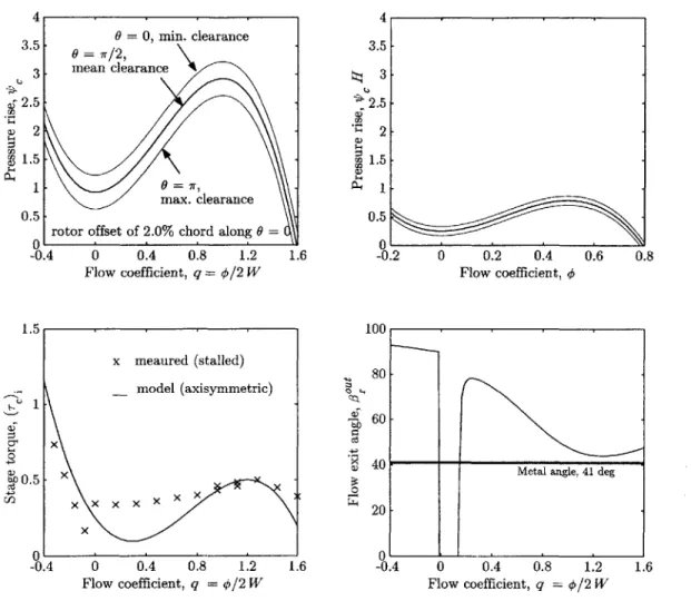
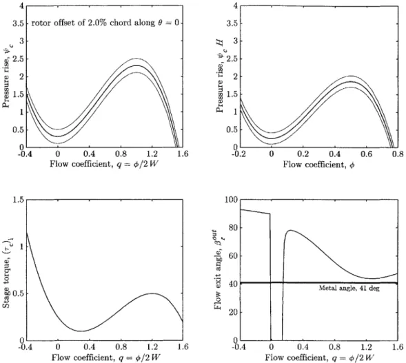
3-3 Pressure-rise and torque characteristics for C3 . . . . 89
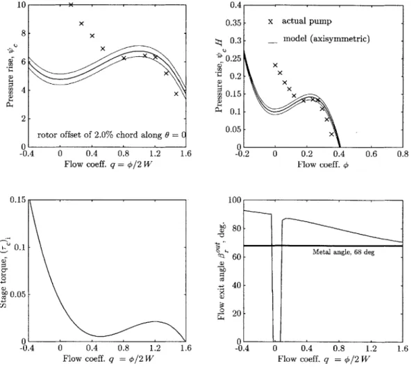
3-4 Pressure-rise and torque characteristics for C4 . . . . 90
3-5 Amplitude of turning force Ft" for different values of flow nonunifor-m ity anonunifor-m plitude . . . . 95
3-6 Amplitude of pressure force FP' for different values of flow nonunifor-m ity anonunifor-m plitude . . . . 96
3-7 Amplitude of unsteady force F1" for different values of flow
nonunifor-m ity anonunifor-m plitude . . . . 98
3-8 Schematic of the phase relationship between the three aerodynamic
forces and flow nonuniformity . . . . 99
3-9 Schematic of main variables in the fixed and the whirling coordinate
system s . . . 101
3-10 Flow nonuniformity and aerodynamic forces for fixed rotor offset as a
function of operating point mean flow
Q:
Compressor Cl, Vwh = 0, r-1.0% chord . . . 108 3-11 Flow nonuniformity and aerodynamic forces for fixed rotor offset as a
function of operating point mean flow
Q:
Compressor C2, vwh = 0, r =1.0% chord . . . . 109 3-12 Flow nonuniformity and aerodynamic forces for fixed rotor offset as a
function of operating point mean flow
Q:
Compressor C3, vwh 0, r-1.0% chord . . . 110 3-13 Flow nonuniformity and aerodynamic forces for fixed rotor offset as a
function of operating point mean flow
Q:
Compressor C4, vwh = 0, r =2.0% chord . . . .111 3-14 Measured and assumed pressure-rise characteristics for the GE LSRC,
system C 3 . . . . 114
3-15 Alford's parameters (*!)tu and (#*i)Pr, for fixed rotor offset of
Com-pressor C3, vwh = 0,r = 1.0% chord . . . . 114
3-16 Comparison between experiment, numerical results, and this model. Results for (/3j*)'u and (/3j1)P', Compressor C3, vwh = 0, r = 1.0% chord116
3-17 Flow nonuniformity amplitude as a function of whirl frequency vwh, for compressor C2 with r = 1.0% chord and different values of
Q
. . . 117 3-18 Flow nonuniformity under steady, forced rotor whirl, for compressor C2at vwh = -0.5 (backward), 0.4 (forward at v1) and 0.75 (also forward),
with r = 1.0% chord . . . 117
3-19 Aerodynamic forces for compressor C2 under forced backward whirl at
v7Wh = -0.5, with r = 1.0% chord . . . 118
3-20 Aerodynamic forces for compressor C2 under forced forward whirl at
3-21 Aerodynamic forces for compressor C2 under forced forward whirl at
Vwh = 0.75, with r = 1.0% chord . . . . 120
4-1 Coupled system linear stability boundary in the Q, - x parameter
space: case of compressor C2, centered rotor, all parameters are at
nominal values.(v = 0.23 and B = 0.1). . . . . 128
4-2 Effect of rotor's natural frequency (v) on the coupled system linear sta-bility boundary: compressor C2, centered rotor, all other parameters
are kept at nominal values, (B = 0.1) . . . . 129
4-3 Effect of compressor tip clearance sensitivity on linear stability bound-ary of the coupled system: compressor C2, centered rotor, three values of 0, v = 0.2 all other parameters are kept at nominal values, (B = 0.1). 131
4-4 Linear stability boundary of the coupled system: compressor C1, cen-tered rotor, four values of v, all other parameters are kept at nominal
values, (B = 0.1). . . . . 132
4-5 Linear stability boundary of the coupled system: compressor C3, cen-tered rotor, four values of v, all other parameters are kept at nominal
values, (B = 0.1). . . . . 133
4-6 Linear stability boundary of the coupled system: compressor C3, cen-tered rotor, four values of v, all other parameters are kept at nominal
values, (B = 0.1). (Note the change in the abscissa scale). . . . . 133
4-7 Linear stability in the design parameter space: combining the two
coupling parameters as V'ceX, for compressor C2, all other parameters
are at nom inal values. . . . . 134
4-8 Linear stability in the design parameter space: compressor C1, for four different operating flow coefficients. All other parameters are at their nom inal values. . . . 135 4-9 Linear stability in the design parameter space: compressor C2, for four
different operating flow coefficients. All other parameters are at their nom inal values. . . . 136 4-10 Linear stability in the design parameter space: compressor C3, for four
different operating flow coefficients. All other parameters are at their nom inal values. . . . 138
4-11 Linear stability in the design parameter space: compressor C4, for four different operating flow coefficients. All other parameters are at their
nom inal values. . . . . 139
4-12 Linear stability boundary of the coupled system: compressor C2, off-centered rotor, two values of v, all other parameters are kept at nominal
values, (B = 0.1). . . . . 140
4-13 Linear stability boundary of the coupled system: Comparison between
the centered and off-centered rotor, compressor C2, v = nominal, all
other parameters are kept at nominal values, (B = 0.1). . . . . 141
4-14 Eigenvalues and eigenvectors at crossing of stability boundary: for
compressor C2, centered rotor, nominal v = 0.23, and B = 0.1. . ... 143
4-15 Eigenvalues and eigenvectors at crossing of stability boundary: for
compressor C2, centered rotor, high v = 0.75, and B = 0.1. . . . . 144
4-16 Eigenvalues and eigenvectors at crossing of stability boundary: for
compressor C2, centered rotor, nominal v = 0.23, and B = 0.1. . . . . 146
4-17 Multiple equilibrium points at high coupling: compressor C1, X = 0.01,
v = 0.23, and B = 0.1. . . . . 147
4-18 Multiple equilibrium points at higher coupling: compressor C1, X =
0.03, P = 0.23, and B = 0.1. . . . . 148
4-19 Schematic depiction of stability boundaries on the compressor map. . 149
5-1 Demonstration of post-instability behavior: rotor whirl at high Qe =
1.32 for compressor C2, no gravity, X = (0.5)10-3, nominal v = 0.23,
and B = 0.1 . . . . 153
5-2 Demonstration of post-instability behavior: rotor whirl at low Qe =
1.08 for compressor C2, no gravity, X = (0.5)10-3, nominal v = 0.23,
and B = 0.1 . . . . 154
5-3 Demonstration of post-instability behavior: rotor whirl at low Qe =
1.08 for compressor C2, no gravity, X = (0.5)10-3, nominal v = 0.23,
and B = 0.1 . . . . 155
5-4 Demonstration of how coupling alters post-instability behavior: Re-sponse to initial conditions for compressor C1, centered rotor, v = 0.44
5-5 Bifurcation map for compressor C2, centered rotor, X = 0.0, (0.5)10-3, nominal v = 0.23, and B = 0.1. . . . . 160
5-6 Map of post-instability behavior of compressor Cl: deep surge for
un-coupled case, X = 0, v = 0.44, and B = 1.0. . . . . 162 5-7 Map of post-instability behavior of compressor Cl: rotating stall for
coupled case, small initial conditions in
Q,
X = (0.5)10-3, v = 0.44, and B = 1.0 . . . . 163 5-8 Map of post-instability behavior of compressor Cl: classic surge andro-tating stall for coupled case, large initial conditions in
Q,
X = (0.5)10-3,LIST OF TABLES
3.1 Nominal and fixed values of nondimensional parameters for different
prototype compression systems. . . . . 92
4.1 Summary of scenarios of losing system stability for compressor C2, and
identification of different modes of instability. . . . . 142
B.1 Compression system parameters for different prototype systems. . . . 176
NOMENCLATURE
A A, (An) a, b, (an, bn) (AR),, (AR)br B C e F, f (F)2 G, g H,W h i,j,k k LI, LE,1L l, lz M, Mst m N, Nst P P, P Q, q R, r S S t AreaAmplitude of the first (nth) harmonic of flow nonuniformity
Cartesian components of the first (nth) harmonic of flow
nonuniformity
Aspect ratio of rotor blade (h/I), rotor
blade row (lz/R = Acos2
B-parameter, Eq. (2.24)
Rotordynamic damping coefficient
Eccentricity of rotor's center of mass (from axis of rotation) Force, amplitude of harmonaic forcing
Per-stage, nondimensional aerodynamic force
Nondimensional, dimensional gravitational acceleration Parameters of the compressor pressure-rise characteristic Blade radial span (height)
Unit vectors
Rotordynamic stiffness constant
Inlet, exit and total effective duct length Blade chord, blade axial chord
Mass of rotating assembly, mass of one stage of rotating assembly Exit duct approximation parameter, Eq. (2.18)
Number of terms in Fourier series, number of compressor stages
Rescaled pressure-rise coefficient, P = T/H
Static, total pressure
Rescaled flow coefficient, Q = 1/W, q = 0/W
Mean annular radius, rotor radial displacement
Aspect ratio of the compressor pressure-rise characteristic Eigenvalue
Mean rotor speed
Volume, flowfield velocity
Cartesian rotor displacements in the inertial frame Inertial frame of reference
Translating frame of reference (fixed to the rotor center)
Rotating and translating frame of reference (fixed to the rotor disk) Rotating (whirling) frame of reference (fixed to the tip-clearance asymmetry)
/3, /3
O1 lr, ls 17, (T7n) 07 0 A7 Ae o
He, rs wh p o-r Te, (rc); 00 TcO, Tei,... x ~, eCc, N9CsAbsolute flow angle, blade (metal) angle Relative flow angle, blade (metal) angle
The Alford
#
parameter, Eq. (3.22)Nondimensional throttle coefficient Rotor, stator blade stagger angle Tip clearance
Damping coefficient
Phase angle of the first (nth) harmonic of flowfield nonuniformity Angular (whirl) displacement of rotor center, circumferential coordinate
Inertia parameter of rotor blade rows, all compressor blade rows
Rotor natural Frequency, fraction of Q, (v = w/Q)
Helmoholtz, rotating stall, and whirl frequency, all fraction of Q Nondimensional time
Nondimensional coefficient of nonlinear rotor stiffness Density
Detuning parameter
Total, per-stage compressor torque
Coefficients of compressor torque characteristic
Annulus-averaged, total axial compressor flow coefficient Circumferential compressor flow coefficient
Flow potential
Aerodynamic-rotordynamic coupling parameter Total-to-static system pressure rise coefficient
Static-to-static, total-to-static compressor pressure-rise characteristic
Cartesian form of averaged, cosine and sine moments of 7p,
U V, v X, Y XY Z xyz XY*/ x*y
Greek
Ng, ~c, g7Ps
Oco
OCE
Polar form of averaged, cosine and sine moments of ,
Shut-off value of V). (Note that coH is the shut-off value of
4')
Sensitivity of compressor pressure-rise characteristic to
tip-clearance, 0, = -9
Rotor rotational (spin) frequency (Q = U/R), rotor natural
frequency (w = V/k/M)
Superscripts, Subscripts and Other Operators
Xin Xtu, X out Xpr, 7Xun Xda, xst, Xns Xgr Xha XAs, XA,I,E,P,T Xz, Xe Xy, XE, .. X, x X
(.)
6(-)(.)
Value at inlet, exit plane of blade row
Quantities related to turning, pressure, and unsteady force contributions
Quantities related to damping, linear stiffness, and nonlinear stiffness forces
Quantities related to gravity, harmonic excitation forces Quantity related to rotating stall
Referrence to locations A, I,... along the compression system, Figure 2-1
Reference to the ith rotor blade row, the (i - 1)th stator blade row, ...
Components along the direction of Z, y',
E,
... Quantity at equilibrium (fixed) pointMatrix, vector
Derivative of X with respect to time (t and for dimensional
and nondimensional quantities respectively) Averaged quantity
A quantity for which a rescaled version with no prime
exists, Eq. (2.95)
Disturbance or nonuniform component
Dimensional quantity for which a nondimensional counterpart exists
CHAPTER
1
INTRODUCTION
1.1
Background and Motivation
The design and operation of axial turbomachines are plagued by different types of aerodynamic and structural instabilities such as surge, rotating stall and shaft whirl. These instabilities may subject the machine to forces and stresses beyond what the components are designed for. In addition to the possibility of costly and catastrophic mechanical failure of these components, the mere interruption of operation may be at least as catastrophic (e.g., aircraft jet engines) or as costly (e.g., gas and oil production plants).
Many advances in understanding and dealing with these phenomena have taken place over the past few decades. Nevertheless, more demanding operational and eco-nomic requirements are still posing significant challenges in this field. This study addresses one such challenge; namely, the interaction of rotordynamics and aerody-namics in axial compression systems.
The aerodynamic performance and flowfield stability of axial turbomachines are known to strongly depend on the clearance gap between the tips of the rotating blades and the stationary casing. Across this gap, known as the tip clearance, a leakage flow that traverses the main blade-passage flow is established as a result of the pressure difference between the two sides of each blade. The mixing of the two flow streams
and the growth of the resulting tip vortex as it convects downstream are among the main sources of viscous losses in axial turbomachines. In an axial compressor, for instance, these losses are manifested as a reduction in both pressure rise capability and efficiency, as well as an increase in the stalling mass flow rate (i.e., loss of stability). In general, larger tip clearances correspond to higher losses. Further, change in the mean tip clearance, as well as its circumferential variation, may impact both performance and stability. Such considerations have been the subject of several studies concerned with the flowfield stability of compression systems [31, 56, 57, 34, 44, 30, 28].
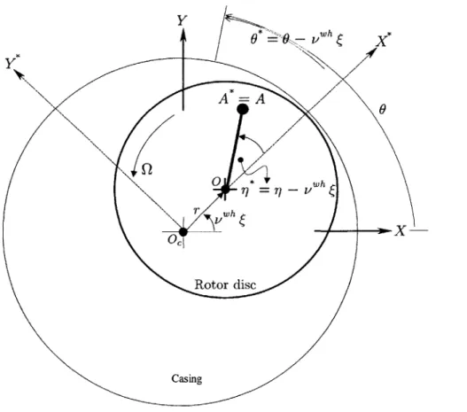
Tip clearance may change either permanently (e.g., due to rotor rubs against the casing), or dynamically as the rotor moves within the casing or as the casing deforms in shape. The motion of the rotor is governed by the structural dynamics of the rotor-bearings subsystem (the study if which is known as rotordynamics) and by the aerodynamic forces acting on the rotor blades and hub. Under certain conditions, these forces can be of such magnitude and direction that they cause the rotor center to follow a fixed orbit, possibly of large amplitude-a self-excited instability known as rotor whirl. Such rotordynamic behavior under the influence of these forces is an important consideration in the design and operation of rotating machinery. Together with several other rotordynamic phenomena (e.g., response to imbalance and oil whip in journal bearings), rotor whirl has long been recognized and addressed in the dis-cipline of rotordynamics as an undesirable structural response of potentially severe consequences [75, 3, 79, 7, 19, 6, 49, 71, 69, 73, 22, 2, 74].
These issues are further complicated by the fact that the dynamic behavior of the flowfield and the rotordynamics in axial compression systems may be strongly coupled. The coupling is established through the dependence of the rotordynamics on the aerodynamic forces described above, and through the dependence of the flowfield on the tip clearance. In other words, as a result of the rotor motion and the associated changes in tip clearance distribution, the flowfield-and hence the aerodynamic forces on the rotor-vary such that they influence subsequent rotor motion and flowfield adjustments, see Figure 1.1.
Flowfield dynamics pressure and velocity distribution
Tip clearance Fluid forces on
variation rotor Rotordynamics rotor displacement Casing Rotor Centerline Rotor ---- o Casing Centerline ompressor Force n Flow-.--- - ' Rotor Nonuniform Ti'P clearance
Figure 1-1: Aerodynamic-rotordynamic coupling mechanism.
There is evidence, both experimental (e.g. Weigl [81]), and theoretical (e,g., Gordan [28]), that this interaction is significant in that, under certain conditions, the rotordynamic behavior may potentially alter (either favorably or adversely) the aerodynamic stability, or vice versa. Ultimately, the understanding of such interac-tion and its implicainterac-tions should open the door for new design and control concepts which yield more reliable and stable machines. Specific examples are given below in Section 1.2.
Given the fact that the performance and stability of axial compression systems are very sensitive to tip clearance variation and distribution-which is directly influenced
the forces generated by the flowfield, it becomes of interest to understand the overall dynamic picture of the coupled system, where all these subsystems are interacting together. It is the mission of this thesis to take the first steps towards establishing this understanding.
1.2
Previous Work
This thesis builds on a large body of available research in the different disciplines that it brings together; namely, aerodynamic stability of axial compression systems and tip clearance effects on the one hand, and rotordynamics on the other. The following is a brief survey of relevant previous work.
1.2.1
Aerodynamic Stability of Axial Compression Systems
General Stability
The early theoretical and experimental work of Emmons et al. [23] established some of the fundamental concepts needed to examine and understand surge and rotating stall. Greitzer [31] utilized these concepts to construct a lumped parameter, nonlinear surge model. His experiments and numerical simulations showed the importance of system parameters in determining the existence and type of instability. The next main step in this field was due to Moore [56] and Moore and Greitzer [57, 34]. These works provided a class of models that capture the dynamics of both axisymmetric, surge-like and nonaxisymmetric, stall-surge-like disturbances under uniform inlet flow conditions. Hynes and Greitzer [44], and more recently Longley et al. [52], extended this approach to account for the effects of stationary and rotating inlet distortions respectively.
Tip clearance Effects
The early work by Smith [67] addressed the effect of tip clearance on axial compres-sor performance and provided a compilation of several experimental data correlating compressor pressure rise to tip clearance. Another compilation of such data was given more recently by Baghdadi [4]. Storer and Cumpsty [45] proposed a simple model to predict losses due to the tip clearance leakage flow in an axial compressor. Horlock and Greitzer [42] developed a linearized steady analysis based on actuator-disc theory to predict the distorted flowfield produced by a tip clearance asymmetry.
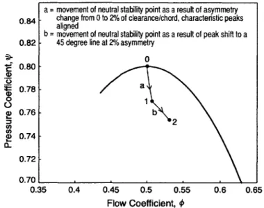
a = movement of neutral stability point as a result of asymmetry
0.84- change from 0 to 2% of clearance/chord, characteristic peaks aligned
b = movement of neutral stability point as a result of peak shift to a
0.82- 45 degree line at 2% asymmetry
0 0.80-0.78 -01 0 a) 0.76 b D 0.74 -0.72 0.70 0.35 0.4 0.45 0.5 0.55 0.6 0.65 Flow Coefficient, 4
Figure 1-2: Effect of stationary tip clearance asymmetry on compressor stability, from Graf et al. [30].
The effect of tip clearance on aerodynamic stability of axial compression systems was addressed by Graf [29] and Graf et al. [30] who used a modified version of the Hynes-Greitzer [44] model to examine compression system stability, both theoreti-cally and experimentally, under stationary tip clearance asymmetry (e.g., distorted casing). Figure 1-2 shows the locus of neutral stability points as the amplitude and wavelength of the asymmetry are varied. The study showed that the asymmetry has a destabilizing effect which is higher than that of a uniform clearance having the same mean. Gordon [28] generalized that treatment to include tip clearance asymmetries
0.8G 0.8 0.75 C) 0 15 CU
045 0.5 Flow coe cient 0.6 _.' -0 hirlingtshaft freq0iincy / 0. 1 1.5
s of stall points on family of axisymmetric characteristics for rotor offset = 0%, ±1%, ±2% chord
(., stall point for uniform flow; o, V"h = 0; x, Vwh = 0.35; +, vh = 1)
Figure 1-3: Effect of forced rotor whirl on rotating stall inception, numerical results from
Gordon [28]. (vwh is the rotor whirl frequency and el is the rotor offset.
that may be rotating at any frequency. He showed that the inception of instability is adversely affected as this frequency becomes closer to a critical value, which is in the neighborhood of the rotating stall first mode eigen-frequency. Figure 1-3 illustrates this effect as calculated for the MIT 3-stage axial compressor.
Control of Instabilities
Several experimental and theoretical works branched from the original Moore-Greitzer model, addressing various modifications and extensions. One such extension is of particular significance. The concept of active control of aerodynamic instabilities, first proposed by Epstein et al. [24], has evolved to be a major area of interest in research and industry. A review of active control concepts is given by Paduano et al. [65]. A relevant example from these active control efforts is the concurrent work
by Spakovszky [72] in which a detailed experimental investigation of using magnetic
bearings to stabilize rotating stall by means of actively moving the rotor and thus adjusting the tip clearance distribution is proposed and assessed.
shaft offset / chord
-- ,E = 2%
shaft offset / chord
---
--=
2%
Locu
Nonlinear Aspects
The nonlinear nature of the Moore-Greitzer type models together with the fact that fully developed surge and rotating stall are ultimately nonlinear, limit-cycle type in-stabilities, have attracted attention from the nonlinear dynamics community. Abed et al. [1] addressed the bifurcation behaviour of the simple, lumped parameter surge
model. McCaughan [54] presented a detailed bifurcation analysis of the
Moore-Greitzer third order model and outlined the post-instability behaviour-including
both surge and rotating stall-of axial compression systems in the B--Y parameter
space (B and -y are the ratio of system compliance to inertia and the throttle coef-ficient respectively). Finally, several investigations (e.g., Nayfeh [62] and Wang [80])
have been conducted to apply nonlinear control concepts to alter the undesirable post-instability behaviour of the system. This, in general, amounts to attempting to change the nature of the bifurcation from subcritical to supercritical. In order to achieve this, Wang [80] theoretically examined the nonlinear aspects of actively con-trolling surge and rotating stall by means of tip-clearance actuation through magnetic bearings.
1.2.2
Rotordynamic Stability
General
The Jeffcott rotor' [46] is essentially stable since it is a damped vibratory system consisting of a mass, springs and dampers. The potential for instability arises from the interaction between centrifugal forces due to whirl-like rotation, and several internal and external forces acting on the rotor. Examples of such forces include fluid forces (such as those generated from tip clearance asymmetry, labyrinth seals flow, and oil flow in journal bearings) and forces due to internal rotor damping. A physical and 'The Jeffcott rotor model is a dynamical representation of the rotor structure that consists of a spinning disc with a point mass supported by springs and impeded by viscous damping. Section 2.2 of this thesis presents a detailed description of this model.
concise description of such effects and how they lead to instability can be found in Den
Hartog
[16]
and Crandall [8]. More recent presentation can be found in Ehrich [18]and Childs [6].
Source and Effect of Aerodynamic Forces Induced by Tip Clearance Asym-metry
As we mentioned earlier, the role of aerodynamic forces in producing rotordynamic whirl has long been recognized. In order to explain rotor whirl, Thomas [75] and Al-ford [3] were the first to suggest simple models to link the whirl-inducing tangential fluid force resulting from a tip clearance asymmetry produced by a displaced rotor. Such models are of a phenomenological nature in that they assume a linear propor-tionality between the tangential aerodynamic force, FA', on the rotor and the radial rotor offset, r, with the proportionality factor, q, being based on efficiency arguments
[3, 18, 6], i.e., FA' = qr. It is argued that the factor q depends on another parameter
which we label as #^", and which is defined as the change of the turbomachine's ther-modynamic efficiency per unit rotor displacement. Alford also carried out a linear stability analysis of a Jeffcott type rotor and showed that the rotor loses stability in the presence of aerodynamic forces according to the simple condition c > q/w,
where c is the damping coefficient and w is the undamped natural frequency of the
rotor structure. There is, however, a great deal of uncertainty involved in estimating
#Al
and in determining its dependence on the turbomachine's geometry and flowfieldconditions.
As an example of the destabilizing effect of these forces on the rotordynamic stability of an actual engine, Akin et al. [2] reported on aerodynamically-induced rotor instability in the TF30 P111 engine. The authors accounted for different sources of destabilizing forces and concluded that, in that case, the Alford-type forces generated on the turbine side of the engine were responsible for the instability. Incorporating an oil-film damper at the bearing was proposed, analyzed and implemented, and was shown to eliminate the problem. The authors concluded, however, that the general
determination of the source of instability is difficult and requires careful testing and analysis.
Measurement and Prediction of Aerodynamic Forces
Following Thomas and Alford's work, there has been a substantial amount of work dedicated to understanding aerodynamic forces in turbomachines. On the turbine side, Song et al. [70] developed and experimentally verified a first-principles based model to predict these forces in an axial turbine. In order to estimate these forces in an axial compressor, Colding-Jorgenson [7] adopted the actuator-disc based model of Horlock and Greitzer [42], whereas Ehrich [19] used a parallel compressor model together with experimental flowfield measurements at different clearance settings.
Very recently there has been a comprehensive study of aerodynamic forces that specifically addresses axial compressors. In a two-part paper by Storace et al. [73] and Ehrich et al. [22], an experimental and analytical effort is reported in which an offset rotor in a low speed four stage research compressor is considered. Detailed measurements of pressure distribution on the two sides of an airfoil as it travels through regions of different tip clearance were recorded and used to calculate the force on that blade. The net force on the rotor was then deduced. In a related work by Spakovszky [71] (also partly reported in Ehrich et al. [22]) aerodynamic forces are calculated by implementing a blade-passage control volume analysis for which flowfield information is obtained from a separate calculation based on a Moore-Greitzer type model. Song et al. [69] also presented an analytical calculation of these forces along the same lines of his earlier work on turbines [70]. Examples of these results are presented and compared to the results of this thesis in Chapter 3.
These efforts have established a foundation for understanding the nature of aero-dynamic forces, and produced a database of measurements against which analytical calculations can be compared. Nevertheless, these efforts are limited in one or more of the following ways:
" The configurations considered are usually static or steady in some sense (i.e.,
either the rotor is fixed or the flowfield dynamics are excluded). The dynamic nature of the problem which ultimately decides the presence and direction of whirl is not addressed, and sometimes is overlooked when making qualitative predictions about stability.
" Except for Spakovszky [71} and Song [69], the force is generally linked directly
to the tip clearance distribution, ignoring the fact that the flowfield velocity and pressure nonuniformity-which is the true source of the force-may be considerably out of phase with the geometric tip clearance distribution. The result is a possibly incorrect intuition about the direction of the net force.
" The force contribution due to the hydrostatic pressure nonuniformity is usually
not accounted for in the rotordynamic stability analysis, and has been over-looked in most previous treatments.
" Most of these efforts are either specific to one configuration or compression
system, restricted to a small range of operating conditions, or are computation-ally intensive. The result is an inability to extract general trends, to establish dependency on parameters, or to build an overall system dynamic model of a manageable complexity.
1.2.3
Aerodynamic-Rotordyanmic Coupling
In the course of active control experiments of rotating stall, Weigl [81] reported on potential coupling between the rotordynamic and aerodynamic domains when he ob-served that the frequency of rotor whirl (due to a deteriorating journal bearing) and that of rotating stall coincided when they were simultaneously present. He also ob-served that the first mode of circumferential flow disturbances had a much higher energy content prior to the onset of instability, as compared to runs with the healthy bearing, Figure 1-4.
during the testing of a new engine which is still in the developmental stage, Ehrich [21]. The problem included the loss of aerodynamic stability (surge event) at the design point in the presence of a rotordynamic, subsyncronous, whirl-like behaviour which has been identified as a subharmonic, nonlinear response to imbalance.
10x 6- 4- 0--0 -2000 0.5 Rotor Rovs. 1.5 -3000 Frequency /12 6- 4-2- 0 0- -:.. -1 0 -2000 0.5 Rotor Revs. 1.5 / -3000 Frequency / Q
Figure 1-4: Effect of rotor whirl on rotating stall inception, data from Weigl [81].
The above overview of previous research establishes strong links between some aspects of axial compressor aerodynamics and rotordynamics in that it sheds light on several ways in which one of the two domains can impact the other. Having said that, and realizing that these two dynamic systems (fluid and structural) are in fact coupled and interacting, the next logical step is to understand this coupling and assess its significance.
1.3
Research Objectives
The mission of this thesis is to present the first integrated treatment of aerodynamic-rotordynamic coupling in axial compression systems. This treatment is aimed at developing a better understanding of phenomena that have not been explored before and that may directly contribute to the design and operation of more stable and reliable compression systems.
To that end, the following research objectives have been identified:
6
" Extend the current understanding of the nature of aerodynamic forces
gener-ated by asymmetric tip-clearance in axial compressors. In particular, establish simple, first-principles based relations, between these forces and a given flow nonuniformity, that accounts for all force contributions and that is valid over a wide range of compressor operating conditions.
" Determine the set of nondimensional parameters governing the coupling of
aero-dynamics and rotoraero-dynamics in an axial compression system, and relate these parameters, and how they scale, to a physical description of the mechanisms at work.
* In terms of these parameters, determine the conditions under which aerodynamic-rotordynamic coupling is important.
* Predict the potential impact of this coupling on the stability of the flowfield and rotor structure. In particular, determine physical arguments and relative design parameter values that are potentially: i) dangerous or destabilizing, and/or ii) beneficial to overall stability.
1.4
Approach and Scope
In order to achieve the above objectives, the following approach is adopted:
Modeling of the coupled System: This involves developing and integrating the
following sub-models
* A fluid dynamic model of the flowfield: A Moore-Greitzer type model is adopted, with modifications to account for tip clearance variation. Such models have been used extensively by many researchers and have been proven to capture the main aspects of the physics relevant to the study of flowfield stability. In addition, the assumptions and limitations of such models are recognized and understood. Once the model is formulated, a Galerkin procedure is implemented to transform the partial differential equations into a compact set of ordinary
differential equations that are more amenable to analytical work and reliable numerical simulations. In that procedure, a truncated Fourier series is used as the basis function to simplify the periodic circumferential dependence.
* A rotordynamic model of the structural dynamics: A simple, Jeffcott-rotor type (mass-spring-damper) model is utilized for the purposes of the "baseline" model. Despite its simplicity, this model is frequently used within the rotordynamic community to demonstrate basic features of the rotor structural response. The limitations of this class of models are also well-understood and can be accounted for.
9 A model of tip clearance effects on compressor performance: This is the first
coupling channel between the two domains. To capture this effect in the current study, the compressor pressure rise characteristic function may be modified with additional term(s) to account for the local loss in pressure rise at locations of large clearances. This is motivated by the desire to avoid modeling the complex details of the tip leakage flow, and is supported by several compilations of experimental data (e.g., Smith [67] and Baghdadi [4]) for different compressors. The same approach has been used by Graf [29] and Gordan [28] in the context of compression system stability
* A model of the aerodynamic forces on the compressor rotor: This is the second coupling channel between the two domains. Unlike the first three sub-models, which are readily available for incorporation into this study with only minor modifications, the force model requires special attention and a different ap-proach. As discussed in Section 1.2, the work previously done on aerodynamic forces acting on compressor rotors has so far been inconclusive as to when and how these forces can lead to rotor whirl instability. In addition, it has not pro-vided a general and simple characterization of how these forces depend on both flowfield nonuniformity and system parameters. In the context of aerodynamic-rotordynamic interaction, in which these forces play a dominant coupling role, it is essential to correctly include all the forces on the rotor in the overall dynamic
model. Therefore, a first-principles, control volume approach is adopted in this study. The unsteady momentum balance on this system gives an estimate of the magnitude and direction of the total force on the rotor as a function of flow-field quantities that are available from the reduced-order fluid dynamic model described above. The combined sub-models provide a compact means of simul-taneously calculating the flowfield quantities and the aerodynamic forces in one unified model, allowing the dynamics of the overall system to be explored. As a by-product of this modeling approach, a generalized characterization of the nature of these forces may be explored in terms of their dependency on system parameters, such as the compressor characteristics, and flowfield pressure and velocity nonuniformities, which in turn depend on tip clearance.
Analysis of the resulting models: To achieve the objectives of this research, a variety of analytical and numerical tools are applied to the resulting models.
" The features of the overall system equations are examined to determine their
numerical structure, physical scaling and other dynamic properties based on the governing nondimensional parameters and general coupling trends.
" Several analytical methods are used to examine the stability of the overall
system and the impact of any possible interaction on both aerodynamic and structural domains. Analytical methods to be applied include linear stability analysis, examination of fixed points, and calculation of bifurcations and limit cycles. Direct numerical simulations will be utilized to demonstrate and verify interesting dynamic trends.
* Comparison with simpler, uncoupled models (e.g., the Moore-Greitzer compres-sor model) is used for assessing the predictive capabilities of this approach in determining the significance of the interaction.
Model Validation. With the exception of the sub-model describing the aerodynamic forces on the rotor, all other sub-models considered in this study have been examined
and utilized both analytically and experimentally by many authors in the literature. Therefore, given the objectives and scope of this study these sub-models are deemed suitable and reliable based on the existing understanding of their assumptions and limitations.
The aerodynamic force sub-model, on the other hand, represents one of the contri-butions of this research, and will therefore be validated against the recently published data by Storace et al. [73] and the accompanying analysis by Ehrich et al. [22], and presented in Chapter 3.
1.5
Thesis Organization
This thesis is organized as follows. In Chapter 2 we present a generalized devel-opment of the aerodynamic-rotordynamic interaction model. We then implement several approximations and assumptions to produce the baseline model upon which the the analysis for the rest of this thesis is based. In Chapter 3 we explore the general features of the interaction phenomena by considering several special, simple cases through which insight may be gained. In particular we investigate the nature of the aerodynamic forces under steady rotor offset and forced rotor whirl at different compressor operating points. Chapter 4 presents the linear stability analysis through which we quantify the impact of coupling on the inception of aerodynamic and rotor-dynamic instabilities. The post-instability behavior is addressed in Chapter 5 where standard numerical tools are utilized to solve for possible limit-cycles and identify potential coupling effects on the nature of the nonlinear behavior. We finally sum-marize the findings of this study, discuss their implications on compression system design and operation, and lay out recommendations for future work in Chapter 6.
CHAPTER
2
DEVELOPMENT OF
AERODYNAMIC-ROTORDYNAMIC
INTERACTION MODEL
In this chapter a generalized model describing the aerodynamic-rotordynamic interac-tion is developed. Equainterac-tions describing the flowfield, the rotating structure and their interaction are derived and the underlying assumptions are outlined. Next, several approximations and simplifications are applied to the generalized model yielding a simpler, low-order baseline model which forms the basis for most of the subsequent analysis. Finally, the main nondimensional parameters governing this baseline model are noted and defined.
2.1
Flowfield
Description
We consider a high hub-to-tip ratio, low speed axial compression system in which the flowfield may be assumed incompressible and two dimensional. Such a compression system may be adequately described by a slightly modified version of the original Moore-Greitzer model [57] which has been extensively utilized in numerous studies concerned with axial compression systems stability. The main modification in this development (as well as in that of Graf [29], Gordon [28], and Spakovszky [71]) is allowing the pressure-rise characteristic of the compressor to depend on the local tip
Y Z = LE
zz
Z Z-= VZ Uniform E Ax'ial Flow A] -ZFigure 2-1: Schematic of the compression system model.
clearance.
In what follows we present a summary of the Moore-Greitzer model. Further details can be found in several references (see for example Moore and Greitzer [57] and Longley [51]).
2.1.1 Derivation of the Basic Equations
Flowfield Quantities
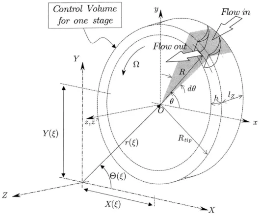
Figure 2-1 depicts an axial slice of the compression system being considered, showing the stationary coordinate system XYZ as well as the system's main components, parameters and flowfield quantities. The axial stations A, I, E, P and T refer to the atmosphere, compressor inlet, compressor exit, plenum, and throttle respectively. In this two-dimensional model, where all radial variations are neglected, the flow
is described by the nondimensional' velocity field (vz(G, Z, ), vo(6, Z,
i)),
and thenondimensional pressure distribution p(o, ZI )/(pU 2). In general, these quantities
are nondimensionalized as follows
Velocity: V = /U = i3/(RQ)
Pressure: p/(pU2) = p/(p(RQ) 2
)
Lengths: For large, system-scale dimensions: Z = Z/R, L, =L/R,
1C = C/R,... and so on.
For small, blade-scale dimensions: r = r/l, E = ?/l,..., and so
on, where 1 is the blade chord.
Time: = tQ = tU/R
At the compressor inlet, point I, it is customary to use 0(0, ) = z(0, 0, ) to indicate the axial flow velocity into and throughout the compressor, also known as the flow coefficient. Further, 0 can be split into two parts
0(0,
)
= <I(') + 6q(Q, ) (2.1)where <1(s) is the annulus-averaged, axisymmetric axial flow coefficient and 60(6,6) is the circumferentially varying (not necessarily small) disturbance representing the angle-dependent flow nonuniformity. These definitions can also be stated as
1 j 2 7r q$(0, ) dO = Ib(6) and
4-
60(0,) dO = 0 (2.2)We also note that, even in the case of uniform axial flow at the inlet (i.e. vo(O, Z =
-L1, 6) = 0 and
vz(Z
= -LI) = constant with 0), the presence of a nonzero 6O at the compressor inlet, point I, mandates the existence of a nonzero circumferential'Dimensional quantities that share the same symbol with their nondimensional counterpart are distinguished by a tilde. For example, 6 and v are the dimensional and nondimensional flow velocities respectively.
![Figure 1-4: Effect of rotor whirl on rotating stall inception, data from Weigl [81].](https://thumb-eu.123doks.com/thumbv2/123doknet/13894980.447713/33.918.125.770.265.502/figure-effect-rotor-whirl-rotating-stall-inception-weigl.webp)