Advanced Aircraft Seat Design: Designing Features for
Improving Comfort and Ergonomy
by
Nikolaos Bekiaris B.S. Marine Engineering Hellenic Naval Academy
SUBMITTED TO THE DEPARTMENT OF AERONAUTICS AND ASTRONAUTICS IN PARTIAL FULFILLMENT OF THE REQUIREMENTS FOR THE DEGREE OF
MASTER OF ENGINEERING IN AERONAUTICS AND ASTONAUTICS AT THE
MASSACHUSETTS INSTITUTE OF TECHNOLOGY SEPTEMBER 1999
@ 1999 Nikolaos Bekiaris. All rights reserved.
The author hereby grants to MIT permission to reproduce and to distribute publicly paper and electronic copies of this thesis document in whole or in part.
Signature of Author: ...
Certified by: ... ...
" Department of Aeronautics and Astronautics -A ugust 12, 1999
Charlie Boppe Senior Lecturer, Department of Aeronautics and Astronautics
N\ 'N Thesis Supervisor
C ertified by: ... ... ... ... ... . ... ... ..
David Burke
Senior Lectu er, Department o Ocean Engineering Thesis Supervisor
Accepted by: ... ...
OFTECHNOLOGY
DEC 28 999
LIBRARIES
Professor Jaime Peraire Chair, Departmental Graduate Office Department of Aeronautics & Astronautics
Advanced Aircraft Seat Design
-
Designing Features for
Improving Comfort and Ergonomy
by
Nikolaos Bekiaris
Submitted to the Department of Aeronautics and Astronautics on May 21, 1999 in Partial Fulfillment of the
Requirements for the Degree of Master of Engineering in Aeronautics and Astronautics
ABSTRACT
This design project examines scientific, creative and innovative means to improve passenger comfort in commercial airplane tourist-class seats during long haul flights. These means have been studied, designed, manufactured and tested consistent with the current size, space and safety constraints.
The project involved three phases. In the first phase, the human factors research area, which includes ergonomics, human physiology and anthropometry, was studied. Moreover, passenger survey and quality function deployment were implemented. For the second phase of the design project a second passenger survey and a product design matrix were used for determining the design concepts that later were manufactured and evaluated. Finally, the features of the two design concepts that improve the ergonomy and the comfort of the seat, and their construction and evaluation have been presented analytically.
The test observations showed that the use of an adjustable lumbar support with an adjustable winged headrest could increase the comfort of the aircraft seat, while the use of a height adjustable tray can significantly increase the ergonomy of the seat.
Table of Contents
List of Figures ...
5
List of Tables ...
6
List of Appendices ...
6
Acknowledgments ...
7
1
Introduction...
8
2
Initial analysis of the problem ...
9
2.1 Seat m anufacturers ... ... ... 9
2.2 Survey A nalysis ... ... ... 10
2.3 Functional Flow Diagram (FFD)... ... 12
2.4 Technical requirements analysis ... ... 12
2 .4 .1 C u sto m er n eed s ... 13
2 .4 .2 In d u stry n e ed s... ... 15
2.4.3 Quality Functional Deployment (QFD)... ... 15
2.5 Approach for second phase ... ... ... ... 17
3
M ain areas of research ...
19
3.1 Anthropometry ... ... 19
3.2 Psychology ... ... ... .... 20
3 .3 M ate ria ls ... ... ... 2 0 3.4 Ergonomics ... 21
3 .4 .1 W ork surface ... 2 1 3.4.2 Seated work-surface height and arm posture... 22
3.4.3 Seated work-surface and thigh clearance ... ... ... 22
3.4.4 Seated work-surface height and nature of the task ... ... ... 23
3.5 General principles of seat design... ... ... 23
3.5.1 Promote lumbar lordosis... ... 23
3.5.2 Minimize disc pressure... ... 24
3.5.3 Reduce postural fixity... ... ... 25
3.6 Specific design recommendations... ... 25
4
Design concepts ...
26
4.1 Seat design attributes for increased comfort ... 26
4 .2 S urvey analy sis... ... 2 7 4.3 Product Design Matrix (PDM) ... 30
4.4 Design concepts... ... ... 31
4.4.1 D esign C oncept # 1 ... 3 1 4 .4 .2 D esign C oncept #2 ... ... 36
4.5 Construction of the design concepts... 38
5
Improving the ergonomy ...
39
5.2 Height adjustable tray... 40
5.2.1 Optimum adjustable tray ... ... ... 40
5.2.2 Implemented adjustable tray... ... 40
5.2.3 M anufacturing of the tray ... 4 1
6
Improving comfort...
44
6.1 Inflatable and height adjustable lumbar support ... ... 44
6 .1.1 D e sig n c o n cep t ... 4 4 6.1.2 Implementation ... ... ... ... 45
6.2 Height adjustable winged head rest for forward sliding seat ... ... ... 47
6.2.1 D esign concept ... 47
6.2.2 Implementation... ... ... ... 47
7 Evaluation of the design concepts ... 49
7.1 Environment ... 49
7 .2 P ro ced u re ... ... 5 1 7 .3 D y n am ic test... ... 53
8 Test results ... 54
8.1 Forward sliding seat ... ... ... ... 54
8 .2 W eb b in g seat ... ... ... 54
8.3 P ressure m aps ... . ... 54
8.4 Dynamic test results ... ... ... 55
8.5 Height adjustable tray... 56
8.6 Inflatable and height adjustable lumbar support ... ... 56
8.7 Height adjustable winged head rest... ... 57
9 Conclusions ... 58
10 Recommendations ... 60
List of Figures
Figure 1: Percentage of times flying per year... ... ... 10
Figure 2: Average duration of flight ... ... ... 10
Figure 3: Class that passengers are usually flying ... ... 10
Figure 4: Aspects of the aircraft seat that require the most improvement... 11
Figure 5: Customer's preferences for an improved aircraft seat... ... 11
Figure 6: Percentage of increased fare for a more comfortable seat ... 12
Figure 7: Functional Flow Diagram... ... ... 14
Figure 8: Elements of a QFD matrix... 16
Figure 9: Quality Function Deployment Matrix... ... ... 18
Figure 10: Comparison of typical postures when horizontal or slanted surfaces are used. (Taken from R ef. 4) ... 22
Figure 11: Lordotic and kyphotic posture of the spine. (Taken from Ref. 4) ... ... .. 24
Figure 12: Forward tilting seat. (Taken from Ref. 4)... 24
Figure 13: O ptim um seat dim ensions ... ... . 25
Figure 14: Level of comfort when getting in/out of a seat with front seat upright or reclined... 27
Figure 15: Average time for flight activities... ... 28
Figure 16: Level of comfort for flight activities ... 28
Figure 17: Preferences for the seat tray ... 29
Figure 18: Preference between a reclinable seat and a lumbar support... 30
Figure 19: Disturbance when the person in front reclines ... 30
Figure 20: Product D esign M atrix ... 32
Figure 21: Design Concept #1: Non-Reclinable seat... 34
Figure 22: Modified design concept #1 ... ... 35
Figure 23: Sliding m echanism ... 36
Figure 24: Design Concept #2: Web-Cushion hybrid... ... 37
Figure 25: W eb-Cushion hybrid ... 38
Figure 26: Seat bottom and work surface heights for the baseline aircraft seats... 39
Figure 27: Tray bracket without the connection point... ... 42
F igure 28: S liding m echanism ... ... ... 42
Figure 29: Height adjustable tray in the lower and higher position... 43
Figure 31: Inflatable lumbar support ... ... ... 45
Figure 32: Principal dimensions of the lumbar support mechanism... ... 46
Figure 33: Lumbar support attached on the seat... ... 47
Figure 34: Graphical representation of the winged headrest ... 48
Figure 35: Graphical overview of the testing environment ... ... ... 50
Figure 36: Front view of the testing environment (dimensions are in feet) ... 50
Figure 37: Testing environment... ... 51
Figure 38: Timeline of the testing procedure... ... 52
Figure 39: Height distribution for the female and male subjects... 53
Figure 40: Forces vs Tim e for the baseline foam ... ... 55
Figure 41: Forces vs Time for the conformal foam cushion... 55
Figure 42: Comparison of the level of discomfort for each seat aspect between the forward sliding seat and the baseline seat ... 56
List of Tables
T able 1: C ustom er N eeds... ... 13T ab le 2 : In d u stry N eed s ... ... ... 15
Table 3: Recommendations for seated work-surface heights for various types of tasks. (Taken from R e f . 4 ) ... 2 3 Table 4: Research weighting coefficients and final averaged scores for each seat attribute ... 33
Table 5: Average statistical data of the subjects ... ... 52
List of Appendices
Appendix 1: First Customer Survey Appendix 2: Second Customer Survey Appendix 3: Experiment Protocol Appendix 4: Experiment results
Acknowledgments
I would like to thank the following people for their help and contribution towards this thesis:
* My team mates: Chong Koh, Narmada, Cheng Han Teo and Zhang Xiaotian
* My advisor, Mr. Charlie Boppe for his advice and inspiring enthusiasm for this project * My other thesis advisor Mr. David Burke, for his guidance and encouragement
* Mr. John Williamson from BE Aerospace for all the information and experience that he provided us during the project
* The following companies that supported us with materials, information and their presence at the project design reviews
>
B.E. Aerospace>
Oregon Aero>
Milliken & Company>
Northwest Airlines* The Hellenic Navy for giving me the opportunity to fulfil my dreams
Finally, most of all I would like to thank my parents for their selfless support and their useful advice.
1
Introduction
Personal experiences while flying in commercial airplanes during long haul flights reveal that current economy-class aircraft seats are not comfortable. The goal of this design project was to find scientific, creative and innovative ways to alleviate passenger discomfort during these flights, through the design of an advanced tourist-class aircraft seat that satisfies existing size, space and safety constraints.
Studies have been focused in three major areas. Increasing passenger personal space, improving the ergonomy of the seat, and increasing comfort. The above goal has been achieved in four phases:
* In the first phase, an initial passenger survey has been performed for characterizing the problem, and a quality function deployment has been analyzed for identifying the user's needs.
* In the second phase, an extensive literature research in the areas of anthropometry, ergonomy, psychology and physiology has been performed. Research for previous and current work concerning aircraft seat design was also conducted. Furthermore a product design matrix has been analyzed.
* The information gathered has been used in the third phase for innovation and implementation, taking into account design constraints.
* The fourth phase included the evaluation of the prototypes by using human subjects.
Finally, further objectives of this project were to achieve a design that will advance the aircraft industry, to provide greater competitive advantage for airlines and seat manufacturers, and meet or exceed all expectations of the project stakeholders.
Five graduate MIT students worked at this project for a six month period, resulting in five independent theses concerning the different aspects of the design project.
2
Initial analysis of the problem
The preliminary analysis of the advanced aircraft seat design has been divided in four parts. In the first part, visits were made to aircraft seat manufacturers where the design and development of aircraft seats were explained. At the second part, a questionnaire was distributed to passengers and responses analyzed. Third, a Functional Flow Diagram (FFD) was constructed and finally, the technical requirements were analyzed with the use of a Quality Function Deployment (QFD).
2.1 Seat manufacturers
Two aircraft seat manufacturers responded to the request for technical advisors. These were BE Aerospace and Oregon Aerospace. All members of the design team visited BE Aerospace's factory, and two also visited Oregon Aerospace.
BE Aerospace is one of the major aircraft seat manufacturers and Mr. John Williamson of BE Aerospace was the main technical advisor for our project. During our visit to the factory, a detailed briefing describing all the stages of the design, production and testing of an aircraft seat was provided. The major seat features and constraints were also analyzed, and the phases of the production were explained. Finally, three sets of aircraft seats were provided for study, analysis and reverse engineering.
Oregon Aerospace is involved in the design and manufacture of cushions for aircraft seats and especially in the use of conformal foam. Based on their experiments, conformal foam cushions support the body better, distribute forces equally resulting in decreasing the pressure concentration points. The occupant can sit for an entire flight without needing to shift positions often, something that is a major cause for discomfort. On the other hand, the manufacture of conformal foam is more
difficult and more expensive.
In addition to the seat and cushion manufactures, Northwest Airlines responded to the same request and provided useful information on the airlines point of view and interests.
2.2 Survey Analysis
In order to determine the specific areas of an aircraft seat that need improvement, a customer survey was send out to students and faculty of the university. This survey can be found in Appendix 1. After analyzing this survey, many interesting aspects came to light, which were eventually used for weighting the different design concepts during the QFD.
Statistical data were gathered from the analysis of the first three questions. Analysis showed that the information gathered from this questionnaire was acceptable for further analysis, since it showed that this sample of people are flying at an average of two to five times per year (Figure 1), the flight duration is between three and ten hours (Figure 2) - the average duration of a long haul flight, and eighty five per cent of this sample of people are flying in the economy class (Figure 3).
60% 2 50% S40% o w 30% E 20% 10% 0% 2-5 6-10 > 10
Number of flights per year
Figure 1: Percentage of times flying per year
50% 50% 42% 40% % 30% ' 20% - % 9% 10% 0% -1-2 3-5 6-10 > 10 Flight hours
Figure 2: Average duration of flight
First 3% Economy 85% Business 12%
The following questionnaire questions were about the different aspects of the current aircraft seat that require the most improvement, and the features that a passenger would like to find on a seat. The current passenger space, the back support and the headrests of the existing aircraft seats are the features that dissatisfied most the customers (Figure 4). So, these three features, according the passengers, should be improved in a new design concept (Figure 5).
60% 50% 40% 30% 20% 10% 0%
Passenger Back support Head rest Footrest Arm rest
space
Figure 4: Aspects of the aircraft seat that require the most improvement 70% 60% 50% 40% 30% 20% 10% 0% 62 % E o3 o M o 23 % MMM,
Figure 5: Customer's preferences for an improved aircraft seat
Finally, the increased amount of money that customers were willing to pay for a more comfortable seat was determined. As Figure 6 shows, while the majority of the passengers demanded a more comfortable seat, less than 32% were willing to pay more than a 5% increase in the airfare, and only 6% more than 10%.
80% -. 70% -o 60% -50% -0' 40% -! 30% -E 20% S10% 0% <5% 26% 5-10 % 10-15 % > 15 % Increase in fare
Figure 6: Percentage of increased fare for a more comfortable seat
2.3 Functional Flow Diagram (FFD)
For the third part of the initial analysis of the problem, a Functional Flow Diagram (FFD) was constructed. The FFD is a pictorial scheme used as a mechanism for portraying system design requirements, illustrating series and parallel relationships, and establishing a hierarchy of system functions. The reason for using the FFD was to highlight the different activities that a passenger is
involved in during a flight and how the different seat aspects can affect these activities positively or negatively, and finally, which features should be improved in order to increase the total comfort of the aircraft seat during these activities.
The FFD provides a detailed map of the passenger activities during the flight, and it is a tool for ideas generation and visualization. Moreover, it can be expanded for a dynamic comfort analysis. It can be seen at Figure 7
2.4 Technical requirements analysis
The final step of the initial phase was to look into the technical requirements for the aircraft seat design. These requirements were derived from the customer and industry needs. The customer needs were extracted from the customers' survey and the analysis of the FFD, and the industry needs from our technical advisors.
For the best analysis and evaluation of the technical requirements a Quality Functional Deployment (QFD) matrix was constructed and analyzed. The QFD matrix is a graphical technique that translates customer needs into parameters or attributes of the product. A weighting coefficient is
80% 6%
ooo
o
70% -50% 4 30=-, 20o,,o10% 0% <5%assigned to each customer and industry need. In total, eighteen customer and industry needs were considered.
2.4.1 Customer needs
The Customer needs that resulted from the survey and the FFD, can be seen in the following Table 1:
Customer Needs Weight
Provide More Personal Space 10
Improved Physical Comfort 10
Higher Adaptability 8 Aesthetic Appeal 7 Better Entertainment 7 Additional Functionality 7 Better Environment 4 Better ingress/egress 3
User Friendly / Easy of Use 1
Table 1: Customer Needs
The weighting coefficients resulted from the degree that each one of these customer needs affected the comfort of the passenger. Provide more personal space, rated as the most important, because according the survey results, it was the most demanding from the passengers' point of view. Improved physical comfort was also important, since it was the driving need for our design.
FUNCTIONAL FLOW DIAGRAM FOR A TYPICAL AIRCRAFT TOURIST-CLASS PASSENGER
Place coil on Load luggage adjacent seat, it' Look for seat and nluggagei overhea
emlple c o ullpltee
spae rPlalce Coal in
Wail for aisle to clear Take off o e
@ 0 Adcoal tol Or Compartment
.lert & O or r 4 _11 1
Walk to seat Do nothing
Stow carry-on luggage under seat in front Look in seat Read safely pocket for oinsc tots Take glimpse out of window rading newspapel or
Doal othgi Roodrl~il
Fasten safety belt
Look ono of
or/& 0. /& 1Wild indo.OI
~
(Inr Adjust body position to get feel of seato
Clone ryrn Examine seat features: entertainmlntch
adjustable mechanisms, arm rsts tn i o e egb
Adjust aty adjustat feaItres Isd eres
foot restt etc.
TShbf offsnnfety bolt fLowerot bool try Ras o tra o
JDo nothing o eloRead
L f
iiLeno Watch musicprepale for Wait frot
in "' ... 1, 1, safety tYtakeoff
~-HOr~
Look oult window scatbell light to~ gofrom pilot video
~
trfl ,YLTor Closr eyres
Recline se ty Keep cat uptight
Shift position in seat
dn no r n Orietdiing, ccpy art of djag rtvislouchingP c ioa elliplyh
Lower food tray
Ra_ ,ef-dlmy
Heve meal atd/r adln
Do notin Do othngto pe
Or/& Stand up to ltnilbrtruhci
Listen to music
qSlee----Interact with flighte attrl' al-Take offsafety bjlltl
Fatnsafety belt
Keep, seat uprig it
.. food 1,.y
Stow away all carry-oil items
List.. i to~r
01
~~~~~~aict
tosftbo ihtI, 1Zin npilot andan 1.1
land and ' go of
Retrieve
Retrieve lgaefo
cary-on orrhadovej
luggage lprlel
from tinder Get Lip Wall
scar in front
Walk I 'l loact tvaPill _ eve Or set nfrn from PlaPt oil coat Ol f" f,1;111 -pflgt Lae-f
"itl allciJ;lls
Do nothing Do othingto Pel 11"
Figure 7: Functional Flow Diagram
2.4.2 Industry needs
The industry needs that were recommended by the technical advisors can be seen in Table 2:
Industry Needs Weight
Provide More Personal Space 10
Improved Physical Comfort 10
Lower Cost of Ownership 10
High Reliability 8
Improved Maintainability 8
Anthropometric Design 8
More Robust Design 7
Aesthetic Appeal 7
Low Weight 6
Good Fleet Compatibility 5
High Upgradability 5
Spares Provisioning 4
Table 2: Industry Needs
The weighting coefficients are based on industry importance. As can be seen, three of the industry needs are common with the customer needs. This was another reason for their higher weightings. Considering the industry needs, lower cost of ownership was the most important. The survey showed that the passengers are not willing to pay a higher airfare for a more comfortable seat, so, keeping the total cost low was very important.
2.4.3 Quality Functional Deployment (QFD)
Different technical requirements that satisfied these customer and industry needs have been evaluated. The QFD matrix made it possible to select the most important technical requirements that were considered in the second part of the project, by minimizing human biases, prioritizing technical requirements and providing requirements traceability. Moreover, conflicts between the technical requirements were traced.
The different elements of the QFD matrix are explained in Figure 8. The customer and industry needs are listed on the left of the matrix. The different technical requirements that satisfy the needs are listed on the top. In the relationship matrix, the strength of the relationship is indicated. Moreover, in the priorities section, the final ranking for each technical requirement is calculated. Finally, conflicts between the technical requirements are indicated in the correlation matrix. Figure 9 shows the final QFD used for the technical requirement analysis of the aircraft seat design and all the technical requirements that were considered.
Correlation Matrix
Technical Requirements
Relationship
Needs Matrix
Priorities Figure 8: Elements of a QFD matrix
The top seven technical requirements that resulted from this analysis where:
* Simplicity of engineering
* Accessory arrangement minimization * Ergonomic / anthropometric design * Minimize number of parts
* Continuous adjustability * Common internal parts * Ease of maintenance
Other technical requirements with close rankings have been retained. These technical requirements were used for identifying the most important seat attributes that should be implemented in the aircraft seat for increasing comfort.
2.5 Approach for second phase
The results of the first phase of the project were used to identify different areas for research. Then, a second customer survey was conducted and by the analysis of a Product Design Matrix (PDM) the design concepts were defined. The third phase of the project included the construction of the design concepts with the implementation of the different design features, and finally the fourth phase included the evaluation of the designs.
Sr CD 0 :Weighting 2 Electrical controlsCD D -E -Mechanical controls Durable materials M Ca ( 0 C-CD 0 = Commonality of design 0 Cinmze number of parts Adjustable mechanims -Light structural materials 'a M CA rL Personal avionics C Improved seatds absorption t ElecIntuitiveal controls isolation SMechanicamize controls CA Simplicity of engineerings DuMaterial matextureials RedFixued seat volume ,Modularity of design Wo o CD te _D La I Commonality of design Minimize number of parts s V ersatile design __ Aesthetic design SEase of mainstenance (cleanirng too) araible loads absorption CIntuitive controls (O Powered adjustments CA Cisual patterns K3oMaterial texture Modularity of design Cost-effective design o"Integrated funtlonality Engineering standard SI I I a I ICompliance to regulations --- ;-..~..~..~ -~-~..~ -a I II -I ___.~I__~_
3
Main areas of research
The first part of the second phase of the project was the accomplishment of detailed research in different areas. The areas of anthropometry, psychology, materials, ergonomics, were studied and general and specific principles of seat design were analyzed
3.1 Anthropometry
The most important aspects of designing a seat involved determining the proper sitting position, the need for variations in sitting positions, and the different chair settings. The major results from the research in anthropometry are presented in the following paragraphs. A more detailed analysis of the findings in anthropometry can be found in Ref. 1
For the proper sitting position, five main areas must be considered according toRef. 5. First, the feet of the passenger must be flat on the floor with knees at an angle of 90 degrees or slightly more. Second, the chair should be at an ideal height according the person who is sitting, otherwise, if it is too high the pressure under the thighs reduces the circulation to the lower part of the leg; while if it is too low, lower back pain may occur. Both cases correspond to discomfort for the passenger. Third, the back of the knees must be two to three inches forward of the chair's front edge. This eliminates any pressure in the popliteal area, which contains many blood vessels and nerves. Fourth, the shoulders need to be relaxed, and finally, the arms should be kept close to the body without having to be held away from the body.
The need for variations in the sitting position and the posture changes are as important as the posture correctness, especially regarding the intervertebral discs in the spine. The reason is that the discs are losing fluid over the course of time because of the weight they carry. The posture changes are essential for helping fluid return to the discs.
There are three major chair considerations that are important for passenger's comfort. First, a chair should minimize, or even avoid pressure concentrations at sensitive parts of the human body. Second, the backrest must support the natural inward curve of the lumbar area. Finally, an inadequate lumbar support places excess pressure on the spine.
3.2 Psychology
In many cases, discomfort can be credited to psychology and especially to the environment that surrounds the passenger. Proper environment control can reduce these effects. Another aspect also in psychology, is the distraction of the passenger from the causes of dissatisfaction, by averting his senses to other, more pleasurable objects. The use of different colors and a correct lighting condition can also improve the feeling of comfort. A more detailed analysis of the psychological aspects can be found in Ref. 2.
3.3 Materials
During the research phase, conformal foam properties were studied, as a material substitute for the construction for the seat cushions. A conformal foam cushion has many advantages.
* It is available in varying degrees of flexibility and rigidity
* It has great shock absorbing properties that can reach 97% of the impact energy in case of an accident
* It conforms to the body shape
* It is breathable; thus it is able to dissipate moisture and perspiration, and
* It has a slow recovery of its original shape from several seconds up to three and a half minutes.
The conformal foam has also the following disadvantages.
* It is very sensitive in temperature and pressure * It is very difficult to obtain laminate with precision
* The foams of varying degrees of flexibility have to be layered together * The conformal foam is less durable in shear stresses, and
* It has high cost.
A more detailed analysis in the characteristics of the conformal foam and the possible uses in aircraft seat design can be read in Ref. 3.
3.4 Ergonomics
The word ergonomics is defined as the science of designing for people. It includes the design of workplace equipment to optimize productivity and to reduce the potential for physical illness or injury. Initially, all the areas concerning ergonomics were studied and then the most important of them were implemented in conjunction with the constraints imposed.
For designing an ergonomic seat it is unlikely that discomfort can be avoided by simply matching each body dimension with the equivalent seat dimension, as if the interface were static. What seems to be critical is the relation of any one dimension with the others and with the expected seated position. So, it is important to determine not only the correct dimensions for each seat feature that would increase the seat's ergonomy, but also the adjustability needed to accommodate the different positions that a passenger takes during the flight for the accomplishment of each task.
Initially, it was important to determine which aspects of the aircraft seat have a direct impact on the ergonomy of the seat. These are the work-surface; the seated work-surface height and arm posture; the seated work-surface height and thigh clearance; and the seated work-surface height and the nature of task, according Ref. 4.
3.4.1 Work surface
Work-surface is defined as the upper surface of a table, bench, desk, counter, measured from the floor. For an aircraft seat this corresponds to the upper surface of the tray. There are two main characteristics of the work-surface; the height and the position with the horizontal. If a work surface is too low, the back may be bent over too far. If it is too high, the shoulders must be raised above their relaxed posture, thus triggering shoulder and neck discomfort. On the other hand, the orientation relative to horizontal is very important, because a slanted surface results in less bending of the neck, more upright trunk, and less flexion than does the horizontal surface, as can be seen in Figure 10.
(a) Horizontal surface
(b)
Slanted
surface
Figure 10: Comparison of typical postures when horizontal or slanted surfaces are used. (Taken from Ref. 4)
3.4.2 Seated work-surface height and arm posture.
The work surface height must permit relaxed postures of the upper arms. Working with relaxed upper arms and elbows at about 900 provides comfort and helps maintain straight wrists, which can be beneficial when performing repetitive tasks.
3.4.3 Seated work-surface and thigh clearance
Basing seated work surface height on arm posture alone can lead to problems. Work surface height is also influenced by seat height, the thickness of the work surface and the thickness of the thighs. The clearance between the seat and the underside of the work surface should accommodate the thighs of the largest user. If the height of the work surface is designed for a larger user, then the smaller users have to raise their seat, so their elbow height is equal to the working height. In so doing, their feet can not touch the floor. So a footrest is also needed to support their feet. With adjustable
height work surfaces, small users can adjust the height so that the working level is at elbow height with their feet on the floor.
3.4.4 Seated work-surface height and nature of the task
Table 3 presents some recommendations for the work-surface heights from various sources based on representative anthropometric data.
Type of Task From To
Reading and Writing 27.5 inches 31 inches
Range for typing desks 23.5 inches 27.5 inches
Computer keyboard use 23 inches 28 inches
Table 3: Recommendations for seated work-surface heights from Ref. 4)
for various types of tasks. (Taken
3.5 General principles of seat design
Many principles must be followed during the design of a seat.
3.5.1 Promote lumbar lordosis
According Ref. 4, when a person is standing erect, the lumbar portion of the spine is naturally curved inward, lordotic, as can be seen at Figure 11. Natural lumbar lordosis aligns the vertebrae of the spine in a near vertical axis, through the thigh and pelvis. However, when one is sitting with the thighs at 90, the lumbar region of the back flattens out and may even assume an outward bend,
kyphotic, as can also be seen at Figure 11. Lumbar kyphosis results in increased pressure on the discs
located between the vertebrae of the spine. There are two main ways to maintain the lordotic posture of the spine. By using a lumbar support (Ref. 5) or by providing a forward tilting seat (Ref. 4). A forward tilting seat opens the angle between the hip and the upper torso, thus producing a more relaxed posture (Figure 12).
Farefts i KefhomRk
Vch arch
Figure 11: Lordotic and kyphotic posture of the spine. (Taken from Ref. 4)
Figure 12: Forward tilting seat. (Taken from Ref. 4)
3.5.2 Minimize disc pressure
The discs between the vertebrae can be damaged by excessive pressure. Unsupported sitting increases disc pressure considerably over that experienced while standing. A reclined backrest at an
angle from 1000 to 1100 can decrease disc pressure. Pressure is also decreased by the use of a lumbar support.
3.5.3 Reduce postural fixity
Postural fixity is the problem that occurs when sitting in one position for long periods without significant postural movement. The human body is not made to sit in one position for long periods of time. The discs between the vertebrae depend on changes in pressure to receive nutrients and remove waste products. Since discs have no blood supply, fluids are exchanged by osmotic pressure. Sitting in one posture will result in reduced nutritional exchange and in the long term may promote degenerative processes in the discs. Chair design can reduce postural fixity by allowing the user to rock in the chair and assume a variety of postures.
3.6 Specific design recommendations
The basic recommendations for a seat design, according Ref. 4 to Ref. 6, can be seen in Figure 13. A good seat design must accommodate from the fifth percentiles of Asian female body dimensions (which on average consists the smallest size of the world population), to the ninety-fifth percentile of North European male body dimension (which on average consists the largest size of the world population). Figure 13 provides the optimum seat dimensions.
Seat height: Seat Back height: Seat depth:
Work surface height: Work surface - seat back: Seat back angle:
Seat slope:
Work surface slope:
/-7---14.5"-- 19" 30.8" -- 39.3" 16" -- 17" 23" -- 31" 18.3" -- 24.5" 90o -- 1100 5o -- (-10o) 0o-- 150
4
Design concepts
4.1 Seat design attributes for increased comfort
After the end of the research phase, the different seat requirements were established. From these requirements, many different seat features were considered and later evaluated with the Product Design Matrix. The seat features that can improve the comfort of the seat were:
* Seat height adjustability
This feature, allows the user to adjust the height of the seat bottom, so that the passenger's feet are flat on the floor
* Seat back angle adjustability
This refers to changing the angle of the backrest relative to the angle of the seat. It allows the chair to support different degrees of recline, which in turn transfers some upper-body weight to the chair backrest and lightens the load on the lower back's intervertebral discs. The backrest angle adjustability also increases the angle between the torso and the thighs, resulting in less pressure on the discs.
* Tiltable seat bottom
This feature refers in changing the angle of the seat relative to the floor, and so, again some upper-body weight can be transferred to the chair backrest.
* Height adjustable armrests
A high armrest results in elevated shoulders and pressure on the undersides of the elbows and forearms. On the other hand, a low armrest causes the passenger to slump or lean to one side to use them. By the use of height adjustable armrests these problems can be avoided
* Padded armrests
* Lumbar support adjustability
A lumbar support should be adjustable in height and in depth. A height adjustable lumbar support can fit a higher percentile of passengers, while depth adjustability can control the size and the firmness of the lumbar support
Beyond the features that improve the comfort of the aircraft seat, three more features that improve the ergonomy of the seat were also considered. These features correspond to the optimum position of the tray in accordance with the passengers' position, and they are:
* Height adjustable tray * Tiltable tray
* Sliding in/out tray
4.2 Survey analysis
A second passenger survey was prepared in order to examine in-flight activities of the passengers and their preferences for some specific seat features. The complete questionnaire can be found in Appendix 2. The first question involved rating the level of comfort for getting in and out of the seat in four different conditions. As it can be seen at Figure 14, a major reason for discomfort is a reclined forward seat, since it reduces the passengers' personal space significantly.
Getting in/out of aisle seat w/ front seat upright 40% -.. 34% . 33% 30% ..-.. _ 19% 20% 12% 10% -1 2 3 4 5
Excellent Very Poor
Getting in/out window seat w/ front seat upright 50% ... 40% 40% - -29% 30% 30% -. -20% 11% 10% 2% 1 2 3 4 5
Excellent Very Poor
Getting in/out of aisle seat wl front seat
reclined S40% - 38% 0 o 30% 24% a 20% ---- -12% . 10% 2% . 0% 1 2 3 4 Excellent
Getting in/out of window seat wl front se reclined a 70% -. . O 60% a. 50% -..---o 40%0 ---m 30% 23% lO%/ - - -1 -- t 2. 3... 4 .. 1 2 3 4 Excellent
Figure 14: Level of comfort when getting in/out of a seat with front seat upright or reclined
24% 5 Very Poor at 65% 5 Very Poor
As it was realized from the FFD analysis, during the flight a passenger is involved in many different activities, and the ease of performing these activities has a positive or negative effect on the total level of comfort for the seat. Figure 15 shows the percentage of time for the different activities that a passenger does during the flight, and Figure 16 shows the level of comfort for each activity. The percentage of time corresponds to the real time that a passenger spends during a flight, and not the time that he/she would want to spend. Because the level of comfort for sleeping and working is very low, it is very difficult for a passenger to perform these tasks, and that's why he/she spends more time in reading, a task that is much easier.
Average Spending Time
50% 40% 30% 20% 10% 0% 45%
---
- 24%-- --- - - --
- - -..--
11%5-Reading Working Sleeping Eating Chatting
Figure 15: Average time for flight activities
Reading Eating 36% 39% 16% 7% 1 2 3 4 Excellent Working 5 Very Poor . . . . . . 42% -- 3 -- 15%3% 8% 1 2 3 4 5
Excellent Very Poor
.--. --- 52% 3 -....32% 6% 7% 2 3 4 5 Very Poor Sleeping .. 5_4% 5-0/ --- 23% 17% 3 4 5 Very Poor
Figure 16: Level of comfort for flight activities
50% 40% 30% 20% 10% 0% 50% 40% 30% 20% 10% 0% 60% 50% 40% 30% 20% 10% 0% 60% 50% 40% 30% 20% 10% 0% 2%-Excellent E 1 Excellent ... . .. . . .. . .:: . .. . .. . . .. 6% 2
Moreover, as it has been found from the research phase, the features of the working surface have a major contribution for the level of comfort considering the ergonomy of the seat. So, for the survey the passenger rated the most important features that he/she would like to see in a future design. Figure 17 shows that the most preferred feature is a height adjustable tray, then a sliding in-out tray and finally a tiltable tray.
Height Adjustable Tray
40% -- - - -- - - 40% 30% 0 30% - 23%-- .25% ---- 30% o 20% 13%- w 20% 9% CM 10% J 10% 0% ... , 0% 1 2 3 4 5 0.
Very Much Not at All
Tiltable Tray 40% 30% 20% 10% 0%-Sliding Tray i 22% 1 Very Much 28% 33% No 11% 2 3 4 5 Not at All 35% 10% 1 Very Much 2 3 15% 5 Not at AJI
Figure 17: Preferences for the seat tray
Finally, since a reclined seat has a major negative effect on ingress and egress, the survey asked the respondents to rate their preference between a reclinable seat and the existence of a lumber support. The analysis of the survey shows, that there is a small preference for a lumbar support versus a reclinable seat (Figure 18).
Preference between a lumbar
support and a reclinable seat
M 30% 25% . .- ---.. 20% 6
w
15%S10%
5% 0%9....
a. 1 2 3 4 5Very Much Not at All
Figure 18: Preference between a reclinable seat and a lumbar support
Disturbance when the person in
front reclines
S37%- 40% S 31% . 30% ...30% 22% w 20%--- ... S10% 7% a. 1 2 3 4 5Very Mlich Not at All
Figure 19: Disturbance when the person in front reclines
4.3 Product Design Matrix (PDM)
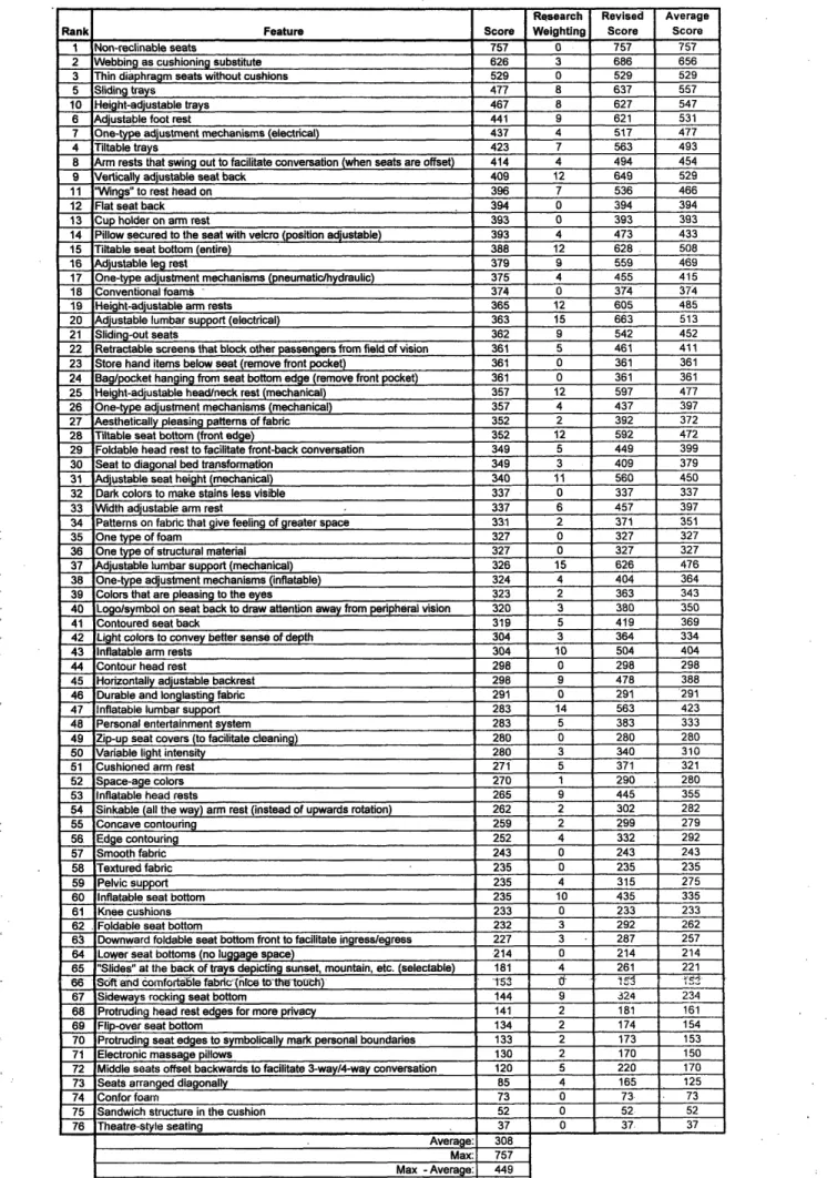
The product design matrix is the second step of the QFD. With this matrix, the different seat features considered to improve the comfort and ergonomy of the aircraft seat were evaluated in accordance with the resulting weightings of the technical requirements from the QFD. Figure 20 shows the detailed PDM. In total, seventy-six different seat attributes were considered. Since the scores resulting from the PDM did not take into account the research weightings, these scores for each seat feature have been moderated according to their relative merits for providing comfort according the information gathered during research. For that reason, even the "Thin Diaphragm Seats without Cushion" ranked third in the PDM, since it does not contribute directly to increase ergonomy
or comfort. In the revised scores it ranked sixth. Table 4 shows the seat attributes that were considered with the corresponding research weightings and their final scores. The final top five design seat features were:
* Non - Reclinable seats
* Webbing as cushioning substitute * Sliding trays
* Height adjustable trays, and * Adjustable foot rest.
4.4 Design concepts
The last part of the second phase of the project includes the definition of the final design concepts. After having the resulting rating for each seat attribute, these ratings have been divided in three categories. These categories were:
* Provide more personal space * Facilitate in-flight activities * Provide better support
Then, at least one seat feature was chosen from each category.
4.4.1 Design Concept #1
For the first design concept, to provide more space, a non-reclinable seat was chosen. A reclinable seat is able to support different degrees of recline, to transfer some of the upper body weight to the back rest, it lightens the load on the lower back's intervertebral disks and increases the angle between the torso and the thighs. This results in lordosis. On the other hand, a reclinable seat is responsible for intrusion into other passenger's space behind the seat. It is impossible for the passenger to effectively use the tray when the front seat is reclined. Recline also reduces the ease of
3 a s, . d 3133 d,, 3 -3 .3 l 33333333 3 or x He ; F I'lWe F- ihting
Patems on la that gie eOlm ol grealr spiee - -l--- I I I. Iu l y Pasing pa.em s o fhbric
- - - - -- -- co 3 s a are lneasmg to the eyes
d ght coWs W vy bhs, sens of dept
ob
3-3 -a - -3 g es33 n 3s 33
- r s- te lbk of trays dcepl g sunsel. mounin, ae (seleW ale
.
- symbl on sei Dsc to draw Menon away trom peripheral vision
Ion and comf3 a te albrck (nice to the touch)
o Z iP-up Sea cover (o factitate cleaning)
oPnudhg Sea edges to symboIcaly mek person t bound1ries .1-rotr head es edges for pvacy.more
w W Retracele creens that black other p.ss.gers f.. field of v,n Seats artrad diagonaMiy
, a Shding tyl-'-']' 3- O e t3.ys S- m o Height- aunle ta f ,-I -.3 t. . 'e3 P3 3M.3Motion)3sts3 a a dm adjustable arm rst 1. d W hoder on ie aon w Su wuhin amrem
i.le head rests . r
fdal che te fro." ald acl Conversationw w da st.l foot restP
djustale leg rest
v-'acay 3 3ust 'a3 b333333
+Horzontaly adjustbhle backrest
M. ca1, eontouring
dg. con.mAg
W Ilow secured to Me seat ai, 1crb (position adjustadle) oecn massage plum
- - - m- u ble lumbar supprs (lec-Ial
I
-I blw e lu 33mbr 3 supor 3Inflata 3
I I 1 .1 Pelic support
dsutable se&d height (mechanica) Inlastable se
bon-Coale sa b11MtI o (. re)
o 33 L -ownward foldee set ottom t(ont ege) te r tont ingres-g &res Sr tal seat bonom (front edge)
a s gb t seats n ddomrdable seat
aw I r seat Iuoms (no luggage pace) a ys rocng sei baotlom
on-e.na-- e seis
I 'hn diaphragm Seae Rhautl ushiong I. o b * g aS cushioning su taelult
Sa njmh structure In the cushin do
e tmo hand iems bew seatremove in poker b o lagpocket hanging from .eat ottom edge (remove frnt pocket)
w Knee cushions
TTJ1-, a. to dron.. e trnlforCa
Q . asliae light Inlteanty Co ;ope ra oam
S_4 1. 4 1 1 onvenonal oamsc r e
-df f.m..
a a a l lsylm a o stud e let m .ea
o w d d, l ne-yp am justmn mehanisms liflann le) 0 d, natype adjsmentmecanism mecmn
o m nsyPde austme mec aisms (pneummai mthydrauc) - Oe-type adustmet machisml (ewmicm)
-3 33- 33 3 33333333333333333333333 3- - - - 3 - 3 3 33 333333.333 33 3- 33 33 3-3 33 3333333 s _ _ 33 '-3o 33 - 3 3 33 3333333333333333in 3 3- 3333-3333333 -3 33 333333333333333333333333333 3 3- 33m 33m~ -upo -3 333333333333 -33 3 3 3 3 3 3 3 33 333 3333333.3 3333' 3 3 3 33- 3 3333333333333333333 33 33 33 -3* -3ph '3-3ni~l 33 3 3 3 3333333333333333 33 33 33 3- 33333 333333333 33333331 33 3 3 33333333333333333333)333333333 3- 33 3-3 , -3 -3 -3 -3 33 3333333333lr 33 3- -3 -3s 33o 33onodD 33 33l~t -3 33333333333333333D 3- 33 33 33 33 33 33~o 33ro 33 3333333333333)I 33 33 33 33 33r 333333333333 '3 -3 33 -3 33 33 3 33 3333333333333 -3 3- 33 33~ -3~c 33 3 -333 3 3- 3 3 3 3333333333333 3-3o -3 33s -3 33-3 3- 3333333333333333333333 33 -- 3 3 33333 333333333333333333333333 33 - 3 - 3 33 33 3 33333333333333333333333333 33
~~ ~ ~
33-~
333333333333D __ _ _ _ _ c~pcs _ __ _ _ _ _ _ I. l h-F-.-=Ee?~Research Revised Average
Rank Feature Score Weighting Score Score
1 Non-reclinable seats 757 0 757 757
2 Webbing as cushioning substitute 626 3 686 656
3 Thin diaphragm seats without cushions 529 0 529 529
5 Sliding trays 477 8 637 557
10 Height-adjustable trays 467 8 627 547
6 Adjustable foot rest 441 9 621 531
7 One-type adjustment mechanisms (electrical) 437 4 517 477
4 Tiltable trays 423 7 563 493
8 Arm rests that swing out to facilitate conversation (when seats are offset) 414 4 494 454
9 Vertically adjustable seat back 409 12 649 529
11 "Wings" to rest head on 396 7 536 466
12 Flat seat back 394 0 394 394
13 Cup holder on arm rest 393 0 393 393
14 Pillow secured to the seat with velcro (position adjustable) 393 4 473 433
15 Tiltable seat bottom (entire) 388 12 628 508
16 Adjustableg rest 379 9 559 469
17 One-type adjustment mechanisms (pneumatic/hydraulic) 375 4 455 415
18 Conventional foams 374 0 374 374
19 Height-adjustable arm rests 365 12 605 485
20 Adjustable lumbar support (electrical) 363 15 663 513
21 Sliding-out seats 362 9 542 452
22 Retractable screens that block other passengers from field of vision 361 5 461 411
23 Store hand items below seat (remove front pocket) 361 0 361 361
24 Bag/pocket hanging from seat bottom edge (remove front pocket) 361 0 361 361
25 Height-adjustable head/neck rest (mechanical) 357 12 597 477
26 One-type adjustment mechanisms (mechanical) 357 4 437 397
27 Aesthetically pleasing patterns of fabric 352 2 392 372
28 Tiltable seat bottom (front edge) 352 12 592 472
29 Foldable head rest to facilitate front-back conversation 349 5 449 399
30 Seat to diagonal bed transformation 349 3 409 379
31 Adjustable seat height (mechanical) 340 11 560 450
32 Dark colors to make stains less visible 337 0 337 337
33 Width adjustable arm rest 337 6 457 397
34 Patterns on fabric that give feeling of greater space 331 2 371 351
35 Onetype of foam 327 0 327 327
36 One type of structural material 327 0 327 327
37 Adjustable lumbar support (mechanical) 326 15 626 476
38 One-type adjustment mechanisms (inflatable) 324 4 404 364
39 Colors that are pleasing to the eyes 323 2 363 343
40 Logolsymbol on seat back to draw attention away from peripheral vision 320 3 380 350
41 Contoured seat back 319 5 419 369
42 Light colors to convey better sense of depth 304 3 364 334
43 Inflatable arm rests 304 10 504 404
44 Contour head rest 298 0 298 298
45 Horizontally adjustable backrest 298 9 478 388
46 Durable and longlasting fabric 291 0 291 291
47 Inflatable lumbar support 283 14 563 423
48 Personal entertainment system 283 5 383 333
49 Zip-up seat covers (to facilitate cleaning) 280 0 280 280
50 Variable light intensity 280 3 340 310
51 Cushioned arm rest 271 5 371 321
52 Space-age colors 270 1 290 280
53 Inflatable head rests 265 9 445 355
54 Sinkable (all the way) arm rest (instead of upwards rotation) 262 2 302 282
55 Concave contouring 259 2 299 279
56 Edge contouring 252 4 332 292
57 Smooth fabric 243 0 243 243
58 Textured fabric 235 0 235 235
59 Pelvic support 235 4 315 275
60 Inflatable seat bottom 235 10 435 335
61 Knee cushions 233 0 233 233
62 Foldable seat bottom 232 3 292 262
63 Downward foldable seat bottom front to facilitate ingress/egress 227 3 287 257
64 Lower seat bottoms (no luggage space) 214 0 214 214
65 "Slides" at the back of trays depicting sunset, mountain, etc. (selectable) 181 4 261 221
66 Softand comfortable fabric(htce toth toth) 153 0 i .i
67 Sideways rocking seat bottom 144 9 324 234
68 Protruding head rest edges for more privacy 141 2 181 161
69 Flip-over seat bottom 134 2 174 154
70 Protruding seat edges to symbolically mark personal boundaries 133 2 173 153
71 Electronic massage pillows 130 2 170 150
72 Middle seats offset backwards to facilitate 3-way/4-way conversation 120 5 220 170
73 Seats arranged diagonally 85 4 165 125
74 Confor foam 73 0 73. 73
75 Sandwich structure in the cushion 52 0 52 52
76 Theatre-style seating 37 0 37 37
Average: 308
Max: 757
Max -Average: 449
Weighting to assign to each research area: 20 Revised score = Score + (research weighting) x 20
Table 4: Research weighting coefficient and final averaged scores for each seat attribute
• : .
" ..
...
The non-reclinable seat concept eliminates these disadvantages, but in order to have the same effects as the reclined seat for the recline posture of the human body, an inflatable and height adjustable lumbar support must be considered. Other attributes that were used for providing better support were a height and tilt adjustable head/neck rest (preferably the one from a dentist chair) and a seat bottom constructed with conformal foam. Finally, for improving seat ergonomy, a height adjustable tray was chosen. A sketch of this concept can be seen at Figure 21.
Height-adjustable and tiltable dentist chair headrest Hand pump for lumbar support Height adjustable tray Multi-layered foam seat bottom
Figure 21: Design Concept #1: Non-Reclinable seat
During the manufacture of this concept, many difficulties surfaced and necessary modifications were implemented. These modifications were:
A lumbar support that would have the same effects as a reclined backrest, had to be very big and so, very difficult to implement. The initial non-reclinable seat concept was changed to a forward sliding seat. In that way, if the backrest is kept at the upright position, it has the same advantages as the non-reclinable backrest. On the other hand, when the low end of the backrest slides forward, the seat has the same effect as a reclinable seat without its disadvantages. By doing that modification, a smaller lumbar support could be used.
* The existing tiltable mechanisms for the headrest are very expensive, so, considering the limitations in the total final cost of our design, this mechanism was not used.
* The headrest of a dentist chair provides the best support for the head and the neck, but only in one specific posture. A passenger takes many different postures during the flight, so, this kind of headrest was not practical.
* Finally, because a forward sliding concept was chosen, a seat bottom with conformal foam could not be fitted.
After these modifications, the final design concept was considered. It consisted of a forward sliding seat, with a height adjustable tray, a height adjustable headrest and an inflatable and height adjustable lumbar support. This final constructed seat concept can be seen in Figure 22. The manufacture of the mechanism that allowed the backrest to slide is described inRef. 2. In general, the backrest has two frames, one external permanently attached at the seat frame, and one internal. The
lower part of the internal frame is allowed to slide to preset positions while the upper part has a pivoting point that allows the internal frame to pivot and slide. This mechanism allows the seat to achieve the same angles (100' and 1150 degrees) between the backrest and the seat bottom as a reclined seat. Figure 23 shows the sliding mechanism details. The construction of the other features will be described in the following chapters.
Figure 23: Sliding mechanism
4.4.2 Design Concept #2
For the second design concept, a webbing backrest was chosen as the main feature for providing more space. By eliminating the thickness of the cushion of the backrest, a direct increase in passenger personal space can be achieved. A web backrest also provides better seat ventilation, and has a lower flammability. On the other hand, a cushioned seat bottom was chosen to be implemented for three reasons. First, the space restrictions are horizontal and not vertical. Second, a foam seat bottom can be used as a floatation device in case of an emergency. Finally, by substituting only the cushion backrest with a web backrest, there is a gradual introduction of a radical technology. The other features that accompanied the specific concept were again a height adjustable tray for improving the in-flight activities, and a height adjustable winged headrest and a mechanical lumbar support for providing better support. A sketch of this concept can be seen at Figure 24.
Winged headrest Webbed
djustable seat back
umbar r upport Height-adjustable tray Cushioned seat bottom
Figure 24: Design Concept #2: Web-Cushion hybrid
The biggest problem that was faced during the construction of this concept was the attachment of the height adjustable headrest in the webbed backrest. So, an existing head/neck rest was used at the final design. Moreover, since the webbed backrest provided more space it was possible to use a conformal foam seat bottom. For the construction of this concept, a Herman Miller Aeron-chair was acquired. The backrest of this chair was disassembled from the seat bottom, and was attached to the main frame of a current aircraft seat with exactly the same mechanism, allowing the backrest to recline. The headrest is from a current aircraft seat, with a small modification in order to be attached at the webbed backrest. Figure 25 shows the Herman Miller's Aeron-chair and the final web-cushion hybrid concept. More details on the manufacture and evaluation of this concept can be found in Ref.
Figure 25: Web-Cushion hybrid
4.5 Construction of the design concepts
The primary purpose for the construction of the prototypes was to test how the implementation of these features can improve the passengers' comfort during long haul flights. For that reason, the designed mechanisms and the materials that were used for their implementation and test have not been checked for compliance with the existing safety regulations, or optimized for being easy in use.
5
Improving the ergonomy
In both concepts, the seat aspect that improves the ergonomy of the seat is the height adjustable tray. Before manufacturing the height adjustable tray, it was necessary to calculate the limits for the adjustability for the fifth percentile of Asian women (lower limit) to ninety-fifth percentile of North European men (upper limit).
5.1 Baseline tray
As has been analyzed in the research phase, there are two principle dimensions for the proper ergonomic design of a seat, the seat bottom height and the work surface height. With the proper combination of these two principal dimensions, it is possible for the passenger to have the proper arm posture and thigh clearance while working in the aircraft seat. The current dimensions of installed airplane seats are 19" for the seat bottom height and 24.25" for the work surface height. By subtracting these two values, and taking into account the thickness of the tray (0.5"), the current thigh clearance for the passenger is only 4.75". According Ref. 6, the thigh clearance for the fifth percentile of women is 4.6" and for the fiftieth percentile is 6.1", while the corresponding clearance for the male population is 4.8" and 6.3". So, it can be noticed that the baseline tray can accommodate properly only a very small percentile of the female population.
0.5Figure 26: Seat bottom and work surface heights for the baseline aircraft seats