ANNUAL TECHNICAL REPORT
DIVERTOR AND LIMITER TECHNOLOGY
PFC/RR 80-26
Editor: T. F. Yang
Becker
Blackfield
Erez
Gierszewski
L. Jones
M. Lidsky
Mc Murray
B.'
D.
E.
N.
J.
A.
M.-Mikic
B. Montgomery
J.
Rapperport
Todreas
Tracey
Wan
L. Xue
T. Brogan (MPSCO)
Franklin Chang (Draper)
E. T. C. Cheng (GA)
J. Fisher (Draper)
D. Morgan (McD. D.)
H.D.
E.
P.J.
L.
J.
TABLE OF CONTENTS
1.0 Summary
1.1
Overview
1.2 A Review of the Progress in FY'80
1.2.1 Workshops
1.2.2 Outside Activities
1.2.3 Work Accomplished or in Progress
2.0 Workshop Summary
2.1
Summary of Divertor Technology Workshop Held at MIT in April
2.2 Summary of "Plasma"-Material Workshop Held in Albequerque in June
3.0 Divertor Magnetics
3.1
Bundle Divertor
3.2 Hybrid Divertor
4.0 Divertcr Target and Limiter Study
4.1
Design Window Study
4.2 Limiter Concepts
4.2.1
Oscillating Limiter
4.2.2 Alcator Limiter Study Concept
4.3 Divertor Target Concepts
4.3.1 Solid Target
4.3.2 A Supersonic Gas Target
4.3.3 Poloidal Divertor Collector Systems
5.0 Divertor Shielding, Insulating Materials and Coils
5.1
Shielding Consideration
5.2 Insulating Materials
'5.3 Cryogenic Normal Coils
6.0 Bundle Divertor for ISX-B and ISX-C
7.0 Simulation Source
1.0 Summary
1.1 Overview
This report contains three major sections: (1) a review of the progress in the technology planning effort, and in the divertor concept development: (2) the combined technical conclusions and recommendations from the Divertor Technology Workshop at Albuquerque; and (3) individual contributions on specific topics.
The program has brought an awareness on the part of a wide spectrum of the experts in and outside the fusion community, and has generated a number of innovative concepts, such as a hypersonic gas jet target, phase-change solid-pellehargets, metal window pumping, and helium selective pumping (helium fly paper), high pressure cryosorption, and oscillating limiter concepts.
The major design achievement has been that a good bundle divertor configuration for ETF and INTOR has been found which can satisfy critical requirements for both engineering and physics.
The following sections expand on the specifics of these topics. Further details of the work in each area are given in the sections dealing with specific topics.
1.2 A Review of the Progress in FY80
The Divertor Developmental program was initiated in November, 1979, and ORNL contracted for the design and facricate of the ISX-B bundle divertor in August, 1979. The activities accomplished are listed in the following subsections:
1.2.1 Workshops
To inform the community of this project and to seek feedback, MIT has at various times arranged the following workshops:
* Target Miniworkshop, March 5, 1980, DOE * Miniworkshop on ETF poloidal divertor
* Divertor Technology Workshop, April 10-11, 1980, MIT
1.2.2 Outside Activities
Full support of ETF divertor design, and participation in all levels of ETF Activities
MIT has also actively attended the following workshops to keep this program in line with other projects: * INTOR Bundle Divertor Report
9 Impurity control, Plasma Wall Interaction and Divertor Workshop on February 25-26 at
DOE
0 First Wall/Blanket Shield Workshop, March 1980
* Divertor, First Wall Material and Impurity Control Workshop, JEARI, Japan, March 17-20,
1980
. Sandia "Plasma"-Materials Developmnt Workshop, June 24-25, 1980
1.2.3 Work Accomplished or in Progress
(1) Magnetic concepts development and divertor fabrication
The L-shaped bundle divertor concept has been proven. Many cQnfigurations using different combinations of.L-shapcd coils have been developed and studied. The ripple has been found to be reduced significantly so that the beam particles are contained. An engineering method has also been developed such that the divcrtor can be dismounted as a single unit.
The fabrication of divertor housing and winding for ISX-B has been finished and will be assembled and tested. The complete divertor assembly is anticipated to be shipped to ORNL in the spring of 1981.
In addition to these major accomplishments there is other on-going work listed as follows:
* Three versions of an internal poloidal divertor with minimized current have been obtained. The total current of each of these systems is about 25 MA-T as compared to as high as 100 MA-T for the external systems. An engineering concept for segmenting internal normal coils is in progress. The effort for next year is develophig feasible engineering methods for maintainable internal divertor coil systems.
* An improved hybrid divertor configuration has been obtained and a detailed study is in progress.
- An improved concept of a mousetrap divertor has been conceived. A detailed study will be carried out when the engineering difficulties can be resolved.
* A study on hybrid divertor has been initiated, an extensive study will be carried out when the computational tools are ready.
(2) Divertor Shielding
A one dimensional shielding design study has been carried out by General Atomic and the minimal shield-ing requirement has been established. A three dimensional shieldshield-ing Model for the bundle divertor is in the
planning stage.
A survey of insulation materials is in progress. A follow-on test program on the irradiation and mechanical properties of G-10 insulation material done by MIT at Idaho for another project, is under consideration.
(3) Divertor Target and Limiter (MIT, M EPSCO, McD)
The following areas of work have been pursued at MIT and by outside contractors in order to gain an insight into future program planning.
* Solid target design study
* A specific limiter designed to be tested on Alcator has been carried out by McDonnell
Douglas and is now in a second phase evaluation. Many unique configurations have been
conceived by MIT, and a study is in progress.
* Gas Target (Draper Laboratory)
'
* A supersonic gas jet target has been conceived and studied by Draper Laboratory.
* An innovative oscillating limiter concept which can be cooled by helium and can stand high
local heat load has been conceived.
(4)
Plasnma
Simulation Sources
A number of forms of plasma sources have been evaluated. They have been narrowed down to
decel-lerated low energy neutral beam and Hall accelerator. A design and small scale test of Hall accelerator is in
progress.
(5)
Bundle Div ertor Modeling
A design window scheme has been developed for understanding material performance limits. An
analyti-cal method for modeling a bundle divertor has been developed and detailed computation is in progress.
2.0 Workshop Summary
2.1 Summary of Divertor Technology Workshop held at MIT in April
It is envisioned that the major elements of a divertor technology program
will involve (1)
development of concepts, (2)
development of targets and pumps
to handle the particle loads, (3)
development of testing techniques to
investigate concepts and proof-test components. These program elements will
be integrated with existing or planned divertor experiments such as on ISX-B
PDX and Doublet III, but will also investigate the independent plasma heat
sources which might be appropriate for simulation of the condition in the
.divertor throat and target chamber.
A two-day workshop was called by MIT to discuss the technology issues
involved. The goal of the workshop was better to define the needs of the
divertor program;to assess the status of existing solutions, to reach some
consensus for future directions and to gather the experts in the country to
work together to solve technological problems related to the divertor and
limiter.
The consensus of the workshop was that there are many important near term
pilot scale programs which could be undertaken. The program should not be
limited to the use of confinement experiments alone as test beds. Before
components are put into a tokamak, screening is required, and it is
particu-larly important in investigating novel target and pumping concepts, that some
off-line facility be used for this screening. The near term recommendations
are in the area of pilot-scale experiments to be done either on existing
tokamaks or on largely existing facilities at "off-time". They involve areas
such as material behavior, heat transfer experiments on various target concepts,
and novel divertor and divertorless concept development.
2.1.1
Issues and Discussions
The particle and thermal handling problems for a typical 1000 mw reactor
can be approximated by Table I. In the pessimistic case all the particles
leaving the tokamak in a one confinement time have to be removed and only
small back streaming is allowed. Because of high heat and particle fluxes
high efficiency collectors and high heat transfer technology are needed. The
material problems are also quite severe. The problems would be very much
eased if 80% of the diffused particles could be recycled and a large fraction
of the power can be radiated.
This requires the realization of novel concepts
such as gas target. In dealing with these problems, both older and new novel
concepts have been discussed.
2.2
U
o
t
0 ro -H p U 0 H E 41 -r rd a) -H .I C H o a. o Q.a a) to
4
H Hd a) -d . H a) H Q) 0 4 <~
x~
I 0 Q) 41 4 0 0 C0 0 O 0 U-t 0O HD VI CII VI a:) 4J) co al) 04I (N 0 o U ( 0 4J~ 4 ,- ta U U H H E-Cr 41-) a) C, 'I Hz
H E-H-1 0 41-) C) t0 04 >1 E-4 0 H 04 0 0 0 U S) 0 o H Sro r o-The Issues can then be listed as follows:
1. Can impurities and ash be handled in a divertorless concept?
2. What pressure can be maintained in a divertor chamber?
3. What is a practical heat flux to handle at a divertor target?
4. What surface materials should be used -for the target?
5. Must the impurity control pump all the plasma components in order to remove ash and impurities?
6. Can a magnetic divertor concept be identified with acceptable
engineering requirements and acceptable influence on injected
alpha particles?It was the .general consensus that all the older known concepts suffer problems and all the new concepts have too many unknowns.
Thus, an impurity handling development program (whether it be divertor or divertorless) will have to develop concepts as well as components and an agressive program is required on an appropriate ETF time scale.
The discussions of the workshop were held in four separate groups: the solid target, novel concept, simulation and magnetic concept
groups. Although magnetics form the central roll in divertor tech-nology, it was not the major topic in the workshop because magnetics has been thoroughly discussed in various previous conferences. The summaries of the other three group discussions are given below.
2.1.2 Solid target/limiter
A summary of the solid target aspects has been established and listed in Table 2.
Three major development/design tasks have been identified as follows:
1. Thermal/mechanical test using a thermal source
This task would screen candidate configurations and materials on a macroscopic engineering basis (as distinct from surface physics
2
consideration). The peak heat flux should be of order 1 kW/cm2
The test target area should be about 0.25m2. Water and helium can be equally considered.
2. Surface Physics Development
This task would produce the engineering data on surface physics characteristics (gas retention, release, trapping reflection, sputtering and impurities) necessary to define the design options for solid targets.
3. Composite Test Using a Neutron Beam or Plasma Source
This test would be mounted on the design concept derived from
the two programs above. The source would mockup the particle and. thermal loadings characteristic of a reactor divertor. Conse-quently this test awaits development of a suitable source which could provide the necessary particle energy level over a suitable area with the desired reactor cyclic behavior.
C.) CN Hz 0 co 0 C . rI -V a) C 'a) U) z
z
0 C L q 4-' .C -H H 4-'4Jo
to-4- H~.
M e U a a) m .4 -' 0 .r- a) a) 4-' U) u a) ) 4-4U) 0 W0 S 4 .) 0 a) 440M 4-)o
a C C) a) -0 a) ) - Wu
o
04 Z Lo U) a) -a) Q) 4-4 CU 0 4-(U) 0 m -) rz 41 '-4 C Lo En 0 $4 0 co U) -I 0 ra >1 ro .) LI) (1) tp '-4 4-4 rd 0 o 0 4-) N) r- Q 4-) 4J Q)) -a Nx
O
-4 0 > > Q)Q
a)
E 44 o re o U) -H L .1-i 0 H-- 4.) Un U) c pq 41 tz 0 4-' 4.) -L) L) A) H A '-4 a) 4-' 4-' 04 U H Uz
4-) H 0 o 0 1 U >) 0 '4 4-4 Ui) E-, H0 Lo 0 0 w 0z
U H>1-z 0 0 0 En 41-44) 0 2 I
aN
u
o
o C4 0 Q1) 2 4-4 :z z >1 N H H Vo .14 a)x
4 4. mro 0 U) z 0 41'U 0 -- HN u (N U) 0 9 -P~ (o H-- LC) * H-- 4-)N > U E-Vra1)
0 > Lr) a) 0 Q) H (N (N > U) 4.) H tq r-0e'
a) E 0 1) to 0 .. .. U 4 H 4 0 a)o
2 a( a) U UU 4)~ > 2 9 N~0
u 0 (1) 2 V 4-) rq V) (r.(-4 q( H HH q 04 2.82.1.3 Alternative Concepts
The novel concepts being discussed are listed as follows: 1. Lithium pellet absorber
2. Lithium rain
3. High pressure cryopumping 4. Hypersonic gas target
5. Gas target and helium enrichment
6. Removal of helium with differential pumping method 7. Moving metal belt
Reflect hydrogen and trap helium 8. Window pumping
Reflection of helium and diffusion of hydrogen through the target
9. Electrotatic trapping
10. In-situ or external recoating
2.1.4 Plasma and thermal simulation sources
The plasma and thermal sources can be classified into generic
source and surface heater. The generic sources are the mostdesirable but not yet available. The potential sources are:
1. Neutral beamsThere are high energy and high current pulsed beams available at ORNL and LBL. A low energy and high current beam has also been developed at the University of Wisconsin.
A suitable decellerating neutralizing cell could probably be used to give a very close match to the actual distribution spectrum at plasma edge.
2. Hall accelerators
The Hall accelerators have been studied for possible heating source for- tokamaks. There seems no basic physics reason precluding
steady state .operation. There are many surface heat facilities, such as ARC Jets, E-Beams and radiant heat source available in the nation. In order to use such facilities, some simulator specifi-cations have to be defined. A preliminary list is given below:
Heat flux Ion temperature Electron temperature Species fraction Operating time Operating pressure
Finite size effects
Collination
Duct charge exchange
Cyclic pressures
Alpha-particle effects Cold gas component Magnetic geometry
The ideal test beds are of course the tokamak facilities.'. The tokamak devices with high heat and particle fluxes are ISX-B, PDXr Alcators, PLT and Doublet III.
PROGRAM RECOMMENDATIONS
1. The divertor technology program should be multifacited and make maximum use of existing facilities and experts groups throughout
the country.
2. Miximum use should be made of existing divertor confinement experi-ments like PDX, PDX-Up-Grade and ISX-B to measure parameters of
engineering importance such as divertor duct and chamber parameters and surface plasma effects at the targets. Non-diverted tokamaks, particularly high power density machines like Alcator, should
increase their investigation of non-diverted impurity control. 3. A long pulse tokamak such as ISX-C, can provide the vital link
required before ETF relevant divertor (or divertorless) concepts can be confirmed. The impurity control technology program should take part in the planning of that machine in order to maximize its usefulness to the technology program.
4. The program should not be limited to the use of confinement
machines. Maximum use should be made of pilot scale experiments
on existing or modifiable "off-line" facilities.
5.* A pilot scale design and test program should begin immediately on
one or more potential target configurations to establish realistic design limits.
6. A major activity to develop suitable surface coatings and to
characterize those materials under realistic conditions must be undertaken. These activities can obviously build on the plasma
surface material development programs, but would be more- design
7. The program should encourage the development of novel concepts, which show potential to relieve the possible "Fatal Flaw"
problems associated with current solid target concepts. Off-line facilities and small tokamaks will be particularly valuable in this aspect of the program.
8. Finally, the program should encourage the development of divertorless concepts.
2.2 "Plasma"- Material Workshop in Albequerque - Divertor Group Summary
In accordance with the theme of the workshop discussions, this group was primarily concerned with material aspects of divertor plates (neutralizing targets or collectors). -Lithium pellet, lithium rain, hypersonic gas target, gas target, and other novel divertor target ideas discussed in the April Divertor Work-shop at MIT were only mentioned briefly. The need for material development work as discussed at MIT Workshop is reconfirmed and specifics have been worked out in this discussion group.
An integrated divertor system consists of magnetic, vacuum and target components. It is difficult to single out the material issues. In particular, the effect of the plasma on the material of the plates are closely related to the vacuum condition in the divertor chamber. Lately, a number of proposed novel concepts have presented a very optimistic picture on the requirements of a target. The most attractive concept in the gas target, which may reduce the heat load on a metal plate, is serving-as a neutralizer. The
effectiveness of such a concept for both target plate protection and He management needs to be seen. However, the interaction of plasma with material always exists and the material cannot be
elimi-nated -altogether, especially in the divertorless case. In this discussion group some innovative ideas involved the use of material as both thermal and particle handling have also been proposed.
Therefore, it is agreed that the development of material plates and the understanding of the characteristics under a wide expected
range of conditions is urgently needed.
initial phase, already in progress, the various issues should be
studied for small samples and medium size tiles using existing or
upgraded specialized facilities. The group identified three majorareas of development needing attention during this phase. 1. Thermal-mechanical design
2. Concepts for hydrogen and helium management 3. Surface materials response
Phase II studies are required to bring together information gath-ered in these areas to produce engineering designs and to test these designs where possible under simultaneous heat and particle fluxes with appropriate pumping geometry. Large area test
facilities for this phase have not yet been identified.
The three Phase I study areas are summarized below with
appropriate test conditions. The interaction of these efforts is shown schematically in the block layout (Fig. 1). Although some interaction occurs between the areas, the group felt that at this
stage they should be pursued in parallel. This is justified
under the particle management concept which isolates the three
--a hot, non-ret--aining surf--ace l--ayer --and --auxill--ary H --and He g--as
pumping. Improvements over this approach can then be pursued
independently.Phase I Program
1. Thermal/Mechanical Design
This task would screen candidate heat transfer configurations
and structural materials on an engineering basis. It would test prospective designs for:a) thermal fatigue and shock resistance,
b) internal erosion resistance in the coolant channels and
c) heat transfer correlations and critical heat flux or burnout conditions.
The latter is of concern for future particle management concepts where surface temperatures become important. It was generally felt that the heat transfer to a forced coolant is not too difficult for
2
fluxes of 1 kW/cm or less, over reasonably-sized tile areas.
However, a review of existing correlation data indicated that gaps exist in the forced convection and nucleate boiling regimes,
particularly for high flow velocities at modest pressures. Thus,
the heat transfer correlation and critical heat flux should be
measured where missing for a range of flows, pressures, swirls(internal roughenings) and coolant channel geometries. Although the primary coolant candidate is water, helium gas and liquid metal coolants should also be considered.
Special substrate structural materials of high thermal
conduct-ivity and failure resistance should be explored. Their thermal
2
fatigue and shock resistance should be studied first at 1 kW/cm for
i03 - 104 thermal cycles, then at higher power densities to handlepossible peak conditions.
Sample tiles could be tested with areas
of about 10 x 10 cm, then perhaps 50 x 100 cm tiles or arrays.Novel cooling approaches were discussed as possible
alterna-tives to force-convection. Spray jet concepts using the latent heat
of vaporization of water to cool surface are in existence but their reliability is a question. Heat pipes have been studied for use in2
cooling laser mirrors with uniform heat fluxes of about 0.5 kW/cm
Existing high heat flux facilities must be utilized for the
development of these ideas as well as for more conventional
heat transfer solutions.
2. Concepts for Hydrogen and Helium Management
Novel, innovative ideas and their development are needed to
solve the particle management problem. Here the task is to
store the hydrogen isotopes and helium ash at the collector
plate, remove the helium and recycle the hydrogen fuel to the
plasma. Possibilities for this gas management are:
a) stop, re-emit, and continuously pump both H and He from the
system,
b) trap and outgas He from the plate between pulses (to be
pumped along with some H),
c) trap H, but re-emit and pump He during pulses, then outgas
H between-pulses, or make H diffuse through the metal
*}
d) trap and bury He in the plate for later removal and
process-ing outside the system, and
e) trap and remove He from the system, then desorb and recycle
(as on a belt, disc, drum, etc.).
--He fly paper
Each .concept requires specialized coatings, for the collector
plate, with controlled trapping and re-emission properties.
Development of concept-oriented coating materials and composites
should be pursued. For many of these concepts, in-situ coating
replenishment must also be considered.
Evaluation of management concepts can be done with small
scale experiments. For these tests, simultaneous H and He ion
fluxes are needed over small areas (about .5 x .5 cm).
Although uncertain, ion energies are postulated to be about 17-2 -1
1 keV at fluxes of about 10 cm s1 . No experimental
facilities are known which produce these conditions.
3. Surface Materials Response
A key issue brought out in the initial presentations and echoed in the divertor working group was that of particle erosion. It was decided that one must be optimistic about the particle flux and require it to be a reasonable level. Additional issues per-taining to handling the particle load are:
a) erosion due to sputtering, blistering, chemical, and arcing effects,
b) retention, re-emission, and diffusion of H and He, and c)* radiation damage from H, He, impurities, and neutrons. The task of this area is to evaluate existing and develop new
cnadidate coating/cladding materials with regard to these--issues.
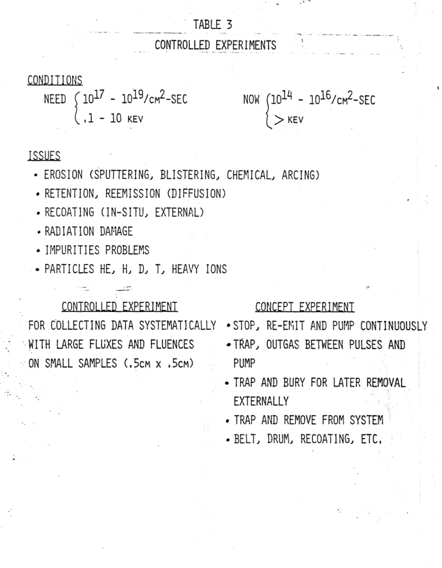
Testing can be done using small scale (.5 x .5 cm areas, orsmaller) controlled experiments. However presently available test conditions of 1014 - 1016 cm-2 sl at 1 keV should be
improved to the proposed fluxes of 10
-
1019 cm
2s- at
.1
-2'keV.
Phase II Program.
In this program the near term goal to make available one or
more reliable modules for ETF is emphasized. Studies are proposed
to test the survival of prototype divertor collector plate designs
under both the thermal and particle loads. Testing should be done over large areas in order to evaluate thermal/mechanical behavior.Fluxes should be averaged over 10 x 10 cm to 25 x 100 cm areas, at 2
1 kW/cm with 1 keV H and He, and in a vacuum environment of about
10-4 Torr. Possible facilities for this testing include modified
neutral beam and plasma sources, and tokamaks. Impurity ashre-moval and fuel recycling would not be necessary in initial designs.
In the advanced design the surface replenishment such as in-situ
coating, the helium and impurity removed and possible fuelrecycling should be considered.
Divertorless Approach
In the divertorless situation the particle and heat removal will be accomplished by specially designed limiter and/or first wall configurations. There is no distinguished line between limiter and divertor plate. The material problems and development needs are quite similar.
In principal, the divertor chamber can be outside the plasma column and thermal and particle problems can be handled externally.
For the divertorless situation, all the thermal and particle loads
have to be handled 'inside the torus. Frequent replacement is
difficult. Modular life time and surface replenishment are
import-ant.For comparison, the group gave some consideration to two
divertorless approaches. The first was that of a rail limiter, which in the very worst case may be expected to experience15 kW/cm2 , 1020 paritlces/cm2 - s. In addition to posing a serious
heat transfer problem, such an approach would require in-situ coat-ing redeposition. The second case was that of allowing the plasma
22
to contact the entire first wall. Here fluxes are about 0.1 kW/cm , < 1017 particles/cm - sec. Again in-situ recoating would probably be required for a reasonable life.
Conclusion and Recommendations
For quick reference the novel concepts, target thermal problems and issues given in the last three secions are condensed and tabu-lated in Tables-1 through 5. The expansion on novel concept is encouraged.
The group recommended small to medium size scale, controlled Phase I experiments in three areas: heat transfer/mechanical
design, hydrogen/helium management concept evaluation, and surface materials response. These should be followed by larger scale, proof-test experiments on prototype designs. Overlap of the two phases is-necessary.
LLU LJ L1 < a) .. Liu u CL 0 6-4 F--J Lu (A ~ I-0) LL LuI (A 2.20 LuJ LL V) LuJ (A F---J L CD, CD >-0 -j L)J LuJ u (A = LuJ LuJ CC Lie Lu a z tz w '0 r-qU a, 0 0 4J CD-L u - j O ct LLu =
-TABLE
1
NOVEL CONCEPTS
1.
GAS TARGET AND HELIUM ENRICHMENT
REMOVAL OF HELIUM WITH DIFFERENTIAL
PUMPING METHOD
2. HYPERSONIC GAS TARGET
3. LITHIUM PELLET ABSORBER
4.
LITHIUM RAIN
5. HIGH PRESSURE CRYOPUMPING
6. MOVING METAL BELT (HELIUM FLY PAPER)
REFLECT HYDORGEN
TRAP HELIUM
7.
WINDOW PUMPING
REFLECTION OF-HELIUM, DIFFUSION OF HYDROGEN THROUGH METAL
8. ELECTROSTATIC TRAPPING
TABLE 2
TARGET THERMAL PROBLEMS, ISSUES, AND RECOMMENDATIONS
1.
FATIGUE (THERMAL SHOCK)
2. INTERNAL EROSION DUE TO COOLANT
3. CORRELATION
TO ESTABLISH PHYSICAL COEFFICIENTS AND BURN OUT CONDITIONS
.
FOR
RANGE
OF
FLOWS,
PRESSURES, SWIRLING OR ROUGHENING
-
FOR
WATER,
HE, (LIQUID
METALS?)
-
FOR 1
KW/CM
2,
THEN HIGHER
-
FOR
10
cm
x
10
cm
SURFACE AREA THEN 50
cm
x
50
cm
OR
25
cm
x
100
cm
-
FOR
APPROPRIATE MATERIALS
(CU,
CU ALLOYS, TA, MO. N6 AND ALLOYS)
-
NEUTRON DAMAGE
4,
NOVEL
APPROACHES
JET, HEAT PIPE, ETC,
5.
ALTERNATIVE APPROACHES
TABLE 3
CONTROLLED EXPERIMENTS
CONDITIONS
NEED
10
17
-
10
19
/cM
2
-SEC
.1
-
10
KEV
NOW
1014
-
10
16
/cM
2
-SEC
KEY
ISSUES
-
EROSION (SPUTTERING, BLISTERING, CHEMICAL, ARCING)
.
RETENTION, REEMISSION (DIFFUSION)
-
RECOATING (IN-SITU, EXTERNAL)
-
RADIATION DAMAGE
.
IMPURITIES PROBLEMS
-
PARTICLES HE, H,
D,
T,
HEAVY IONS
CONTROLLED EXPERIMENT
FOR COLLECTING DATA SYSTEMATICALLY
-WITH LARGE FLUXES AND FLUENCES
ON SMALL SAMPLES
(,5cm
x
.5cm)
CONCEPT EXPERIMENT
*STOP, RE-EMIT AND PUMP CONTINUOUSLY
-*TRAP,
OUTGAS BETWEEN PULSES AND
PUMP
-
TRAP AND BURY FOR LATER REMOVAL
EXTERNALLY
#
TRAP
AND REMOVE FROM SYSTEM
TABLE
L
PROOF TEST EXPERIMENTS
-(NEAR
TERM GOAL)
CONDITIONS
1
KW/CM
2,
10
CM X
10
CM -
25
CM x
100
CM
1
KEV
(H,
HE),--1~O4
TORR
FACILITIES
NEUTRAL BEAMS, PLASMA SOURCE
TOKAMAKS:
ISX-B
DOUBLET-Ill
PDX-
ISX-C
PLT
EBT
ALCATOR
MICROTOR
PARTICLE AND THERMAL LOADING CHARACTERISTICS OF REACTOR DIVERTOR
(ALL
.PARTICLE
COMPONENTS)
SURVIVAL EFFECTS
MECHANICAL, LIFE TIME, VACUUM INTEGRITY
IN-SITU OR
EXTERNAL REDEPOSITION
OF
SPUTTERED MATERIALS
HE AND IMPURITY REMOVAL AND FUEL REGENERATION
(ADVANCED SOLID TARGET SYSTEM)
TABLE 5
ISSUES (DIVERTORLESS APPROACH)
THE FOLLOWING EXTREME CASES ARE LISTED TO SHOW THE
RELATIONSHIP BETWEEN DIVERTOR AND DIVERTORLESS AND THE
DEVELOP-MENTAL NEED.
1.
MOST PESSIMISTIC CASE
-
RING LIMITER
15
KW/CM
2,
10
20
/cM
2
-SEC
REDEPOSITION
IN-SITU COATING
THICKWALL
2, MOST
OPTIMISTIC
CASE
-
FIRST WALL SURFACE
~100
w/cM2,1
<
1017/cm2_
INSITU COATING
RECOMMENDATIONS
PHASE I (SMALL SCALE)
PHASE
II
(LARGE SCALE)
-
CONCEPT EVALUATION
-
PROOF TEST
-
MATERIAL
RESPONSE
-
PROTOTYPE
-
HEAT TRANSFER
3.0 Divertor Magnetics
3.1 Bundle Divertor
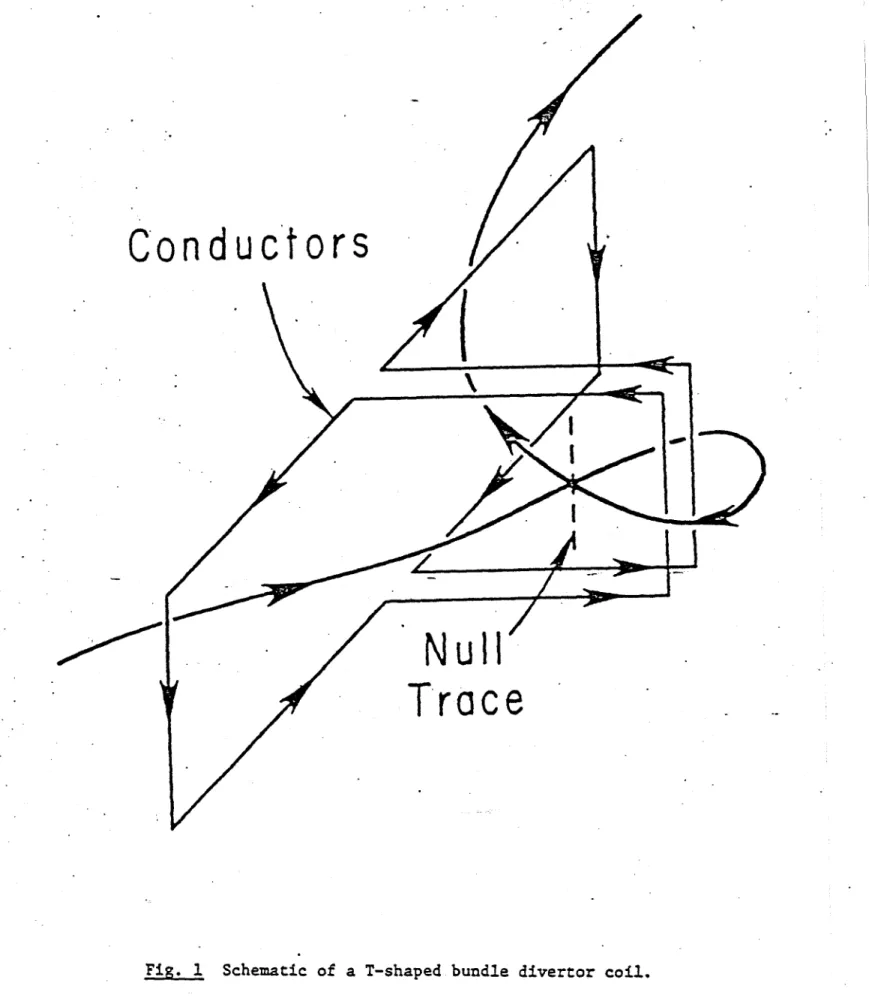
It has been discussed by many authors [1,2,3,4] that bundle divertors can be greatly improved by varying the coil configurations. The designs of a bundle divertor for reactors have been discussed in detail in references [11 and [21 and were found to be feasible. However, there were still many shorwcomings which needed to be resolved. Two of the major shortcomings were: that the ripple is too large, which enhances the loss of energetic particles: that the current required in the divertor coil is too large, and the divertor coils interfere with the TF coils, making the maintenance difficult. To alleviate some of these problems a short T-shaped coil configuration has been proposed by '. Yang [41 and a long T-shaped hybrid divertor has been proposed by H. Furth
[5].
'[his divertor configuration is illustrated by Figure 1. As has been discussed in the 1979 U.S. INTOR report and in reference141,
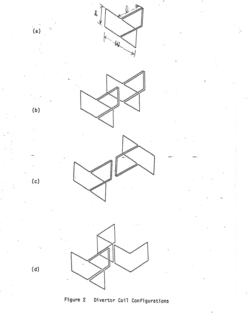
the horizontal conductor elements will increase the divertor field required to cancel the toroidal field and will also enhance the radial component of the diverting flux lines. Such a divertor requires less current and thus produces lower ripple. Another method of reducing the ripple is to use an "X"-shaped four-coil arrangement like a small tokamak, proposed by R. Dory and John Sheffield [2]. All these configurations have been examined in this report It is found that four coil configuration gives the lowest ripple but the associated engineering problems are too difficult. A compromised physics and engineering solution can be obtained from the two T-shaped coil configurations.M agnetic Concept
Magnetic Configuration
The plasma parameters and '[F coil number and size used in this study are listed in Table 1.
'Table 1. Key parameters for INTOR and ETF used in this study. = INTOR ETF Ro = 5.2 m 5.5 m
Bo
4.8 T
5.5 T
a = 1.3 m 1.4 m RTF 10.5 m 11.5 m TF# =12 12*RTI (outer radius)
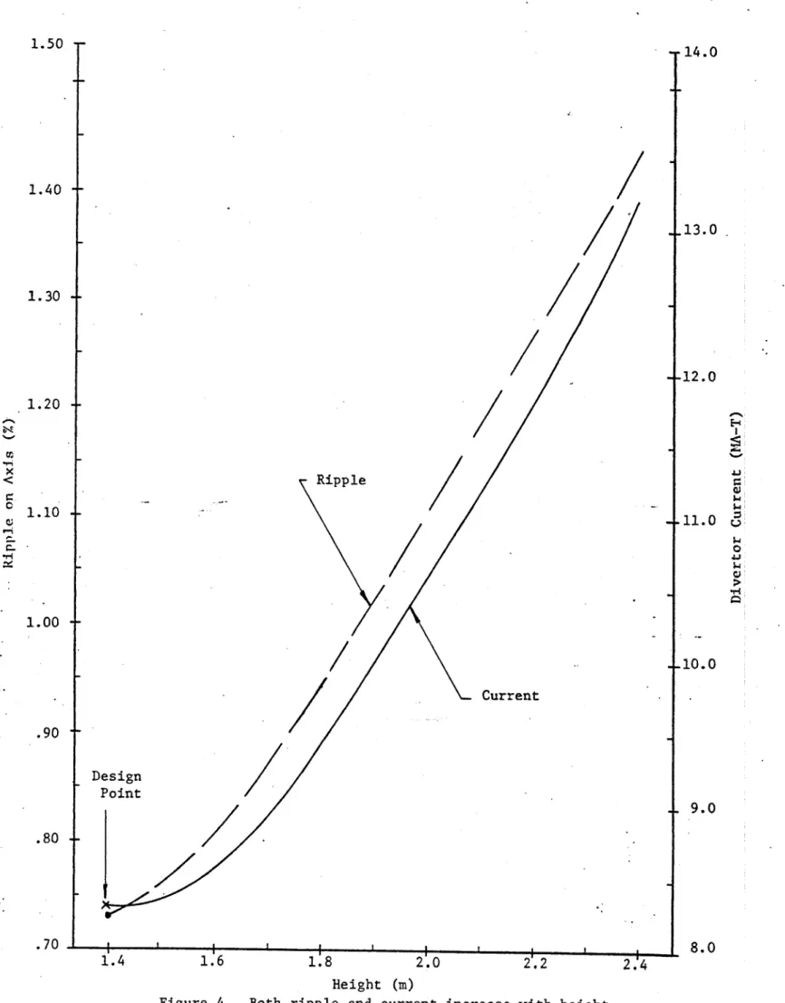
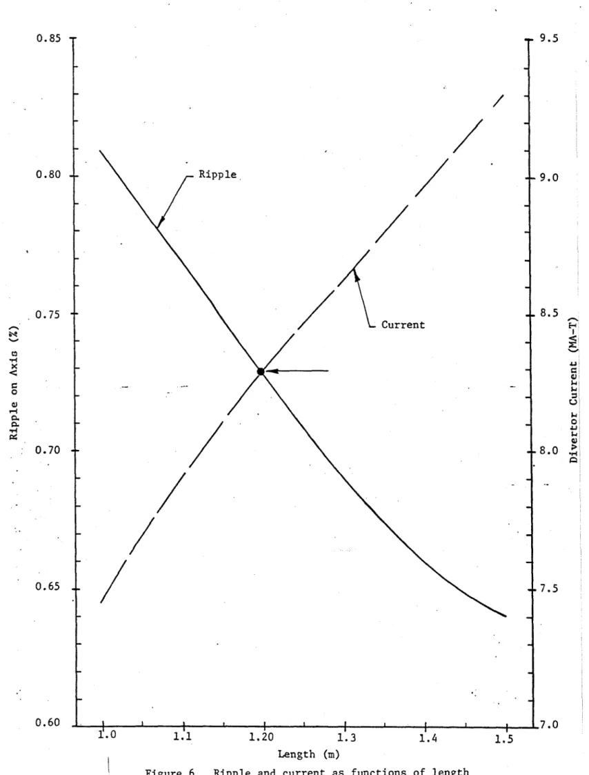
There parameters are chosen partly based on the INTOR and ETF space under consideration, and partly for computational convenience. They provide information and comparison for different sizes and field inten-sities and a flexible range when choosing final parameters. The coil configurations studied here are shown in Figure 2. The typical flux patterns for these coil configurations except (a) are shown in Figure 3. The magnetic configuration of coil type (a) is similar to Figure 3(c). Configuration 3(b) shows the T-shaped divertor with expander coils. It shows that flux can be led to the outside of the TF coils and expanded which makes the particle removal and thermal handling easier. The configuration (c) was considered to be desirable for lower ripple and energetic particle containment. The major disadvantage is that the magnetic intensity at the middle of the diverted flux loop, is 17 Tesla, i.e., the field becomes the strongest and the flux tightest at this point where expansion is needed most The 17 Tesla field makes the expansion nearly bripossible. An attempt has been made to expand the flux or reduce the field intensities by opening the outer legs as shown by configuration 3(c) and by changing the coil shape as shown by Figure 3(d). The gain is insignificant. The radially outward transla-tional force in configuration 3(b) is approximately equal to 20. MIN whereas it is nearly zero in configuration 3(c). In the configuration 3(c) the interaction of the divertor with the TF coil is negligible. From the engineering point of view it is nearly an independent structure since minimal structure is required to hold the divertor assembly in place. As will be discussed in the mechanical section, the divertor can still be designed as a plug-in unit for case (b). Lackplug-ing an adequate method to expand the flux, or to remove the particle and heat load plug-in the very tight space in case (c) and (d), we will concentrate our effort in optimizing case (b). To determine the optimized design parameters, the field ripple on axis and the divertor current are plotted in Figures 4, 5, 6 as functions of height, width and length, while the coil position and separatrix are fixed. Figure 7 plots the ripple and the position of the separatrix as function of current. The design point for INTOR is shown by the dot. The
choice was made based on many engineering and physics considerations. For physics consideration one would like to make the ripple as small as possible. The ripple reduces linearly as the width reduces and the length increases. However, the current requirement increases in both cases. The ripple and current decrease with the height and there is obviously no lower bound. Therefore, physical contraints have to be considered for making
the selection of parameters.
For the convenience of maintenance, the width of the divertor assembly was chosen to be smaller than the gap so that the whole assembly can be removed without interfering with the TF coils. The width and height are also the minimum required to allow 30 cm of shielding on each side, 30 cm of plasma duct, 50 cm of conductor pack, and 10 cm of structure. The amount of shielding chosen is based on the life time of 1 MW-Year. Anything less is dangerously optimistic.
The magnetic field intensitites along a field line of the midplane for the two T-coil case are shown in Figure 8. The ripples calculated from these fields are plotted as a function of major radius and shown in Figure 9. Figure 10 shows the ripple as a function of vertical distance z from the midplane for fixed radii. The ripple curves can be approximated by an exponential function
E(z, R)
=Eo(R)eZ
2/a,
where a = 1.06 for this particular case and E(R) is the amplitude of the ripple given in Figure 10. The expanded ripple for T-coil with expander and for the four-coil type is also plotted in Figure 9. The ripple for~ the T-coil with expander is only 0.4 on axis and becomes positive at a smaller radius and is generally better than the four-coil case. The implication of this kind of ripple distribution on the particle confinement has to be studied. A preliminary calculation of an a-particle orbit and beam particles are given in the following section.
a-Particle Confinement
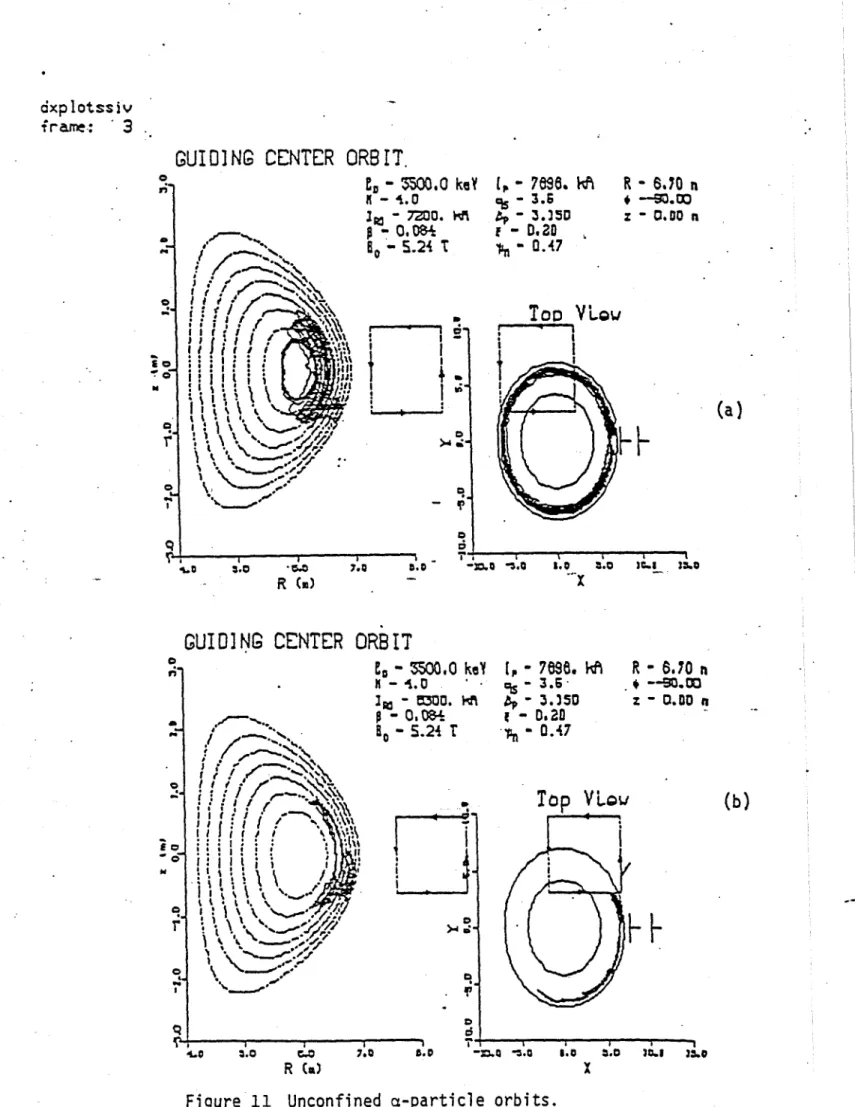
The a-particle orbits have been studied for four cases using the code FLOC developed by Fowler and Rome [6]. In Case 1,the current is 7.2 MA and the divertor height-to-width ratio is 0.58; the orbit is shown in Figure 11, and the banana orbit is not confined. In Case 2, the current is 8.3 MA and the height-to-width ratio is 0.5, but the coils are separated by 1.4 m. The banana orbit is again not confined as shown in Figure 11. In Cases 3 and 4, the height-to-width ratio is 0.5 and the coils are separated by 1.2 m, and the divertor currents are 11.2
MA-T and 6.72 MA-T respectively. In both cases the a-particles are confined as is shown in Figure 12. The ime sequence of the banana shows that the banana steps toward the center of the machine. More has to be studied in order to draw a positive conclusion. However, it does illustrate that the a-particle can be confined for such a divertor system. The typical confined beam particle orbit is shown in Figure 13. The lower picture shows the variation of angular momentum of %hich is time average is nearly conserved.
Structural Concept of ETF Bundle Divertor
A prime requirement of the structure is the necessity to provide easy demounting of the bundle divertor from between the TF coils for servicing requirements.
Four "L"-shaped saddle magnet coils, each approximately 50 cm square in cross-section, 2.4 meters high,
1.2 meters wide, and 1.2 meters long are arranged to form a bundle divertor for the INTOR. These coils may
be constructed of OFHC water-cooled copper conductors run at a current density of less than 6000 a/cm2 in theconductor. 'The substantial forces generated by these windings are delivered to their surrounding structure in three dimension. Hence, the structure conceived is made extremely stiff in all three dimensions.
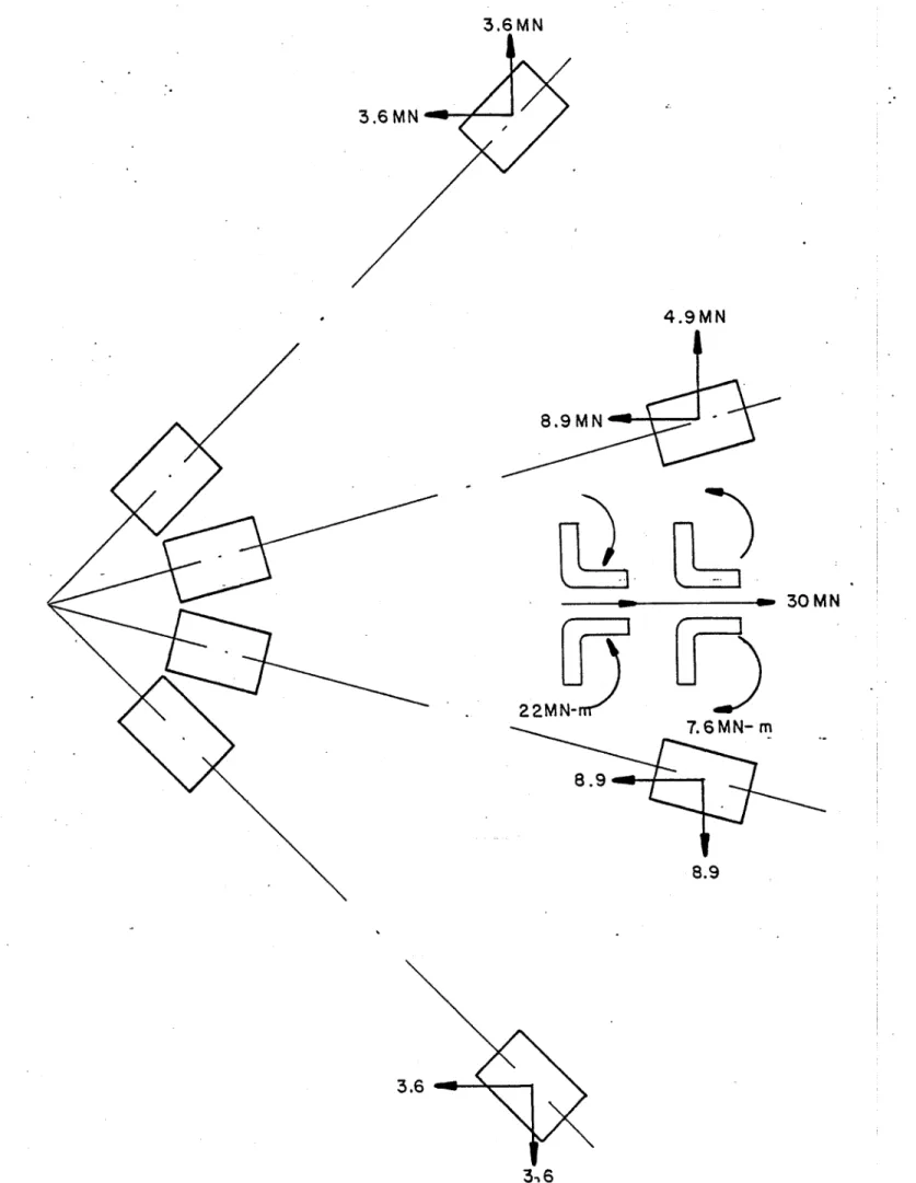
Forces
The net horizontal plane forces delivered by the divertor coils to their containment structure is given in Figure 14. J his figure shows an indicated net radial force of about 30 MN on the whole assembly.
In addition to this net radial force, each pair of coils has substantial opposing forces in the perpendicular circumferential direction, and also in the perpendicular axial direction (out of plane). These forces have been examined in preliminary fashion as have the interactive forces on the adjacent four TF coils.
Structure Concept
The basic structure containing the bundle divertor coil forces consists of two thick 304L stainless steel plates (approximately equal to 15 cm thick) top and bottom, with built-up box beams (keyed and/or welded) of 3041. stainless steel. A mid-plane section of a plan view is shown in Figure 13. lhe box beam sections shown in Figure 15 are schematic in nature, but they do have a geometry that keeps the bending stresses below 20,000 psi, consistent with the ASTM Boiler and Pressure Vessel Code, Section VIII, Division 2.
The four bundle divertor coils are envisioned as being sandwiched between the stainless steel plates mentioned above, with suitable intermediate tie-downs and strong-back cross-beams, to form a large, rigid monolithic assemble which fits between two adjacent TF coils as shown in Figure 16. Keyed joints (demountable) will be made between the monolithic assembly at its edges, and mating plates attached to the two TF coils to support the approximately 16 million pound net racdial thrust of the divertor asssembly. The keyed joints are designed to permit remote removal of the keys and shim plates, which would then permit the radial movement of the entire monolithic divertor assembly outward from its operating position on rails, rollers, or other means.
The stainless steel plates which remain with the TF coil assemblies will have low thernal conductivity compressive links of G-10 in order to effect a satisfactory load link between the TF coils at liquid helium temperature and the divertor at ambient temperature. This compressive load link will have an intermediate liquid nitrogen cooled metallic intercept station to reduce die heat loss along the load path.
Conductor Consideration
Water-cooled copper conductors have been considered for use in theINTOR and ETF bundle divertor. Preliminary examination indicates that the 8.5 X 10³ amp. turns required for each divertor coil can be achieved using a conventional square O.D. conductor (2.3 cm on a side) with a round cooling hole (1.3 cm). For the 400 turns per coil envisioned, the current in each conductor would be approximately 21,250 amperes at a current density of about 5400 amps/cm2 in the conductor (3400 amps/cm2 average within the coil envelope).
H alf-turn (360 cm) cooling with a water flow velocity of 4.6 m/sec (approximately equal to 36.3 litres per minute per half turn) gives rise to a temperature increase of about 21'C to the cooling water at a pressure differential of about 0.79 Atm between inlet and outlet.
Alternatively, full-turn (7.2 m) cooling could be utilized with a water flow velocity of 9.2 m/sec (approximately equal to 72.3 litres per minute per turn) with the same 21*C temperature rise inlet to outlet and a pressure differential of about 5.5 Atm inlet to outlet.
Each front coil, therefore, requires approximately 70 MW of electric power for its operation and about
28,766 litres of water per minute to remove this power. The power requirement for half height coil and current
6.72 MA-T would be approximately 33 MW.
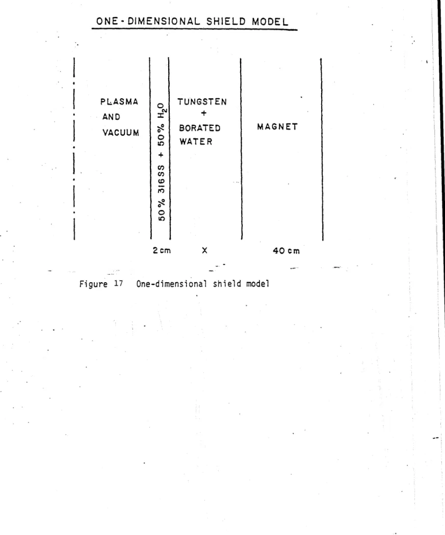
Nuclear Shielding Study
A one-dimensional ANISN calculation has been done to estimate the shielding thickness needed for the
normal conduction operation. The one-dimensional shield model is shown in Figure 17. The dose rate on the
insulation material (epoxy-base material such as G-10) as a function of shield thickness for three shield material
combinations, 10% H20 (B) + 50% W, 30% H20 (B)+ 70% W and 50% H20 (B)+ 50% W have been obtained.
The results show that the 10% H20 (B)+ 90% W shield is the best material combination. The neutron flux, nuclear heating and dose rate arc plotted in Figures 18, 19, and 20, as functions of thickness for the best case.
The dosage on the insulator can be expressed as
D(x)
=D(o)e--0.O8t-3.3333
x10-4where D(o) = 2.5 x 10" Gray/year at MW/M2 wall loading and t is the shield thickness with unit measure
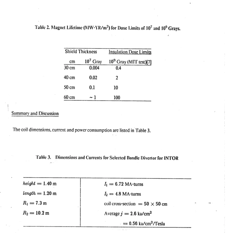
of cm. The lifetime of the insulation for three thicknesses for the dose limits of 107 and 109 Grays are listed in 'rable 2. Since there is 10 cm structure and 30 cm shielding, it is fair to say that the divertor can operate for 1
MW-Yr/m 2. If the duty factor is 50%, the divertor lifetime would be one year for 2 MW/M 2 wall loading. Since
Table
2. Magnet Lifetime (MW-'R/m
2) for Dose Limits of 107 and10'
Grays.Shield Thickness Insulation Dosc Limits cm 107 Gray 109 Gray (MIT test)[71
30 cm 0.004 0.4
40 cm 0.02 2
50 cm 0.1 10
60cm -1 100
Summary and Discussion
The coil dimensions, current and power consumption are listed in Table 3.
Table 3. Dimensions and Currents for Selected Bundle Divertor for INTOR
height = 1.40 m length = 1.20 m. R, = 7.3m
R
2= 10.2 m
I I, = 6.72 MA-turns 12 = 4.8 MA-turns coil cross-section = 50 X 50 cm Average j = 2.6 ka/cm2 0.56 ka/cm2/TeslaThe current required for ETF is 8.3 MA-T and R, = 7.6 m. This divertor is feasible from an engineering and
physics standpoint; the power consumption and lifetime are reasonable, and the replacement is easy. The most significant achievement of this concept is the drastic reduction in size and outboard forces. This fact can be demonstrated by the comparison of INTOR and VFF with a similar reactor design DTHR( ) as is shown in Figure 21. DTI IR uses conventional two coil divertor whose size is more than double that of INTOR and ETF. Further optimism and detailed study of particle confinement are in progress.
nductor
~-~1
N
ull'
Trace
Fig. 1 Schematic of a T-shaped bundle divertor coil.
>
S
(a)
(b)
(c)
(d)
Figure 2
Divertor Coil Configurations
+3.0
+1.0
0
4.0
8.0
12.0
x ..
(c),
-0
I-(d.)
I I +3.0 6+1.0-1.0
-l.10
3.0
4.0
6.0
8.0
10.0
x
m
El
L40
0
LQ~
4.0
6.0
8.0.
10.0
X
Figure 3
4,0
6.0
8.0
->-
0
"1. 0
-3.
r7
1.50 14.0 1.40 13.0 1.30 --12.0 1.20 x 4J Ripple
o
1.10-A
1.10 - 11.0 F--1.00 -10.0 Current .90 Design Point 9.0 .80 .70 8.0 1.4 1.6 1.8 2.0 2.2 2.4 Height (m)Figure 4 Both ripple and current increase with height.
1.50
-1.40 -1.30
-/
I I I I 2.6 2.8 Width (m) 1.20 + 1.10 . .90 .80 .70 Design point x Current ipple R 2.4 3.2 8.5 -.7.5 -7.0 -6.5 L 0 -6.0 -5.5 -5.0 4.5I
0.85 9.5 0.80 Ripple- 9.0 0.75 8.5 Current 0 0.70
8.8.0
0.65 - 7.5 0.60. 7.0 1.0 1.1 1.20 1.3 1.4 1.5 Length (m)Figure 6 Ripple and current as functions of length 3.13
1.00 4
I
a
7.0 8.0 9.0 10.0 11.0
1.10
12.0 Divertor Current (MA-T)
r
K
Ripple Radius of separatrix Design point - 6.60 - 6.55 -6.50 .4 6.0 '64. 0 CO) 0 1 L1 Z 6.40 6. 35 .904
.801
.70 -.60dxpetf5bf 1
frame: 3 ETF bUNDLE ovrgVroG IWO t-cDtL sbri 18:S:5A 09/2b/ev
FIELD MRSNITUDE RLON5 fLUX LIRS I ThROLM1 5
Ii ______ 4-2. z big Sig 1.88
/
* U i U,-a
SFiciure
8
Field
Intensities
alono
the
Field
I NLi
U U i g N IFipure 8
Field Intensities along the Field
Line for Configuration 3C.
V*
I
w ( CDIc
to (o
toemc 1 to o .o C o
to 0
U' )
s
it~~L
LO t...
ES
m cm
1+E E
IIz
-z
0
/
N 0 0 9 C,, -J5
C.)0
C,, -J * 0/7
0~ 0) I.. 0) .9-La~ t0 S1
ID 0 - 0 x LOO - E= to~
C *1 .9-z I ft Iw o .
~e
-iC too
N 3.i7dxplotssiv
frame:
' 3
GUIDING CENTER ORBIT.
c-
0-ED
5.0 kWV
- 7200. W o - 5.24 T .. R(m)
- .U(,I- 7M8. M
% 3.5 - 0.47R
z
-8.70
n - 0.00 ,nToo
YLoW
(a)
- - - I- -- ~x
GUIDING CENTER ORBIT
-a
~
I - * ----a -Lo 3.0 R(a)
S-
3S0.O ko
2.- 5300. Iap
- 004 a-5.24 t
7.0 5.0y
l-
7ese.
M
9$ - 3.5.--.20
- 0.47 -:.0 -3.0 1.0 3.0x
Figure 11 Unconfined a-particle orbits.
-
~
1
~~--. I £0 I N 0a-r
0a-R
z 0:1
-o CrTop VLov
-8.70
f
-0.00
n
(b)
I2.3 I3.0 IGUIDING
CENTER
ORB[T
a -S d1 N Ia
-300.0 .
Ir. -9600. I.
b- 0.084 B0- 5.24 T C 1 0 .0 5.0 , 6.0 - e.0 0.*1
-1 - c.r
eY p -,.-7R. 3.6 Q-8 ; 3. 150e
-0.50
-Pt-0.47
R - G. 70 0 -- 90.00 z - 0.00 * 6~ * *r~./ *7/
* . .7 i.~:I
... V., 1.Is'
11J6 6 6 ~ * jf~~* 6 .~..
1
>k.
I p00
5.0 10.0 ts.0 xGUIDING CENTER ORBIT
IN
*.06 \N.-,.-M.0
k
ii - R -M -7.05.
-S0 - .24 TF-7
1.0 .o (m ,,ey
IF, - 7M.0 M
R
-S 3.350 - o~a-0*-D.20 z . 0.47Top V
Lo
6.70
,*0. 00
Confined a-particle orbits
3.19
Top
VLew
(ok.) * I 0 -S C(c')
Figure 12
Tr T-'a~ -'.o s', l.GUIDING CENTER ORBIT
0 9-) r4 -0 C;1
1
4.0 5.0 -LSD-6.0R fim]
o-150.0 keV
M
2.0
1RC -8000.
NA
-
0.006
80
-5.50
T
0L----0 U0 7.0 8.0 I[ - 4900.
qs -
4.3
P
-
0.532
e
- 0.50
yi - 0.74kA
R
0
zTop VLew
---
H
I I -10.0 -5.0 0.0 I I5.0 Xr.t.
I I 10.0 t5.0 Lews R .. 0. 204. .080 00 20 40 80 00 00 20 40 .J2. 6.0 2.0 4 .0 8 . 0 .0 10.0 t2.0 LO. 16.0 L8.0 20.0 22.O 24.0 .4.0 2 .0TIME (SEC) adOF4
FoTLT-, L pfe, mce
Figure 13 Typical confined beam particle
-
6.50
m-- 90 00
-0.'00
m * *0 a,.. * .0 * * *0 .. * a a . 0~ ** * 'U * S. * **.ada, . U SS *..,~ *~ * *~ .a *U Ut b** J *U ... SI S.. 0** I, .5 '.. *0 *~t*.t * S S *. .0$ ** t,** *I, * S. * 515* . * * I''.' * 5**.* 0* 00' * * * S-0
-Lao 0_ -am 5. I0
j '
3.6 MN
3.6 MN
4.9MN 8.9M M ' S30M N 22MN-7.6MN- m 8.9 8.93-36
Figure 14 Preliminary summation of forces acting on energized bundle divertor coils of INTOR.
-0
C C C C C -J 0 C.) -j 0 u-0I-/
w/
-J 0j e - -. rI
z
0 U)z
w
XF
.! . 0 u 0p 4 E-4 10 0 HIii
LL) 0
z
cLJ 0 0 zo0 L) z a<.i L)U 3.23ONE-DIMENSIONAL SHIELD MODEL
PLASMA
ANDVACUUM
0 0 ILo +o2cm
TUNGSTEN
BORATED
WATER
x
MAGNET
40cm
26
IO-0.2
0.40.6
SHIELD THICKNESS
0.8
GNET
NEUTRON FLUX
AT
DEPTH INTO MA
1.0
(m)
Neutron flux as function shield thickness
21 1:;
27
I
I
NE
E*
Uj-1024
10-10
10-to,
0.0
Figure 18I
iO
20
100--
10--NUCLEAR HEATING
AT
DEPTH INTO
MAGNET
E
-E
-t-L
-0
z
=
IO-L
0
0-50.0
0.2
0.4
0.6
0.8
1.0
10
100.2
0.40.6
0.8
SHIELD
THICKNESS (m)
-V
-V
50%W
50*/ (B)H
20
70%
30%
90% W
10%(B)HZO
-~1
1.0
I'? 97012
w
(B) H20
10
107
S
N. 0w
I-w
C,,0
107
106
0.0
I
I
Fiouro*
?nnoen
@rs-s MIRROR COIL TF COIL DEWAR DIVERTOR COIL DEWAR 40' FLUX BUNDLE MIRROR COIL DEWAR CO"%A: 5
![[PDF] Introduction au logiciel de retouche d’image iPhoto | Cours informatique](data:image/gif;base64,R0lGODlhAQABAIAAAP///wAAACH5BAEAAAAALAAAAAABAAEAAAICRAEAOw==)