Analytical model and simulations of closed-loop
rebreather systems for Earth and Space applications
by
Joana Josan-Drinceanu
Submitted to the Department of Aeronautics and Astronautics
o
Win partial fulfillment of the requirements for the degree of
WM
Master of Science in Aeronautics and Astronautics Q _1
at the
MASSACHUSETTS INSTITUTE OF TECHNOLOGY
June 2015
Massachusetts Institute of Technology 2015. All rights reserved.
/7
Signature redacted
A uthor ......
Department
01Aeronautics and Astronautics
Certified
by...
7k
May 21, 2015
Signature redacted
Olivier L. de Weck
Professor of Aeronautics and Astronautics and Engineering Systems
Thesis Supervisor
Accepted by ...
Signature redacted
\a
Paulo C. Lozano
Associate Professor of Aeronautics and Astronautics,
Chair Graduate Program Committee
Analytical model and simulations of closed-loop rebreather
systems for Earth and Space applications
by
Ioana Josan-Drinceanu
Submitted to the Department of Aeronautics and Astronautics on May 21, 2015, in partial fulfillment of the
requirements for the degree of
Master of Science in Aeronautics and Astronautics
Abstract
Humans in extreme environments, regardless of whether in space or deep in the oceans of the Earth, rely on life support systems to be kept alive and perform their exploration missions. Diving is similar to extravehicular activities in its duration and the need for human respiratory sustaining. This thesis presents the development of an analytical rebreather model, which is the system that recirculates and conditions the air the diver is breathing during a dive. The capability of simulating rebreather performance is currently lacking in the diving commercial and military industry. We believe that the advantages of having such a model are multi-fold: it can be used for mission planning, evaluating the impact of adding a new technology or modifying existing parameters or operational regime on an hardware configuration without per-forming expensive and time consuming hardware tests. An analytical model, like the one developed in this thesis, can also be used in complement with hardware testing to fine tune systems and increase resource endurance through the application of different electronic control strategies.
The developed Matlab/Simulink model of this rebreather is modular and can be generalized to study open, semi-closed or closed circuits, in which the breathing gas used is air, oxygen, nitrox or heliox. The system's operational environment can be the ocean's surface (1 atmosphere), space (less than 1 atmosphere pressure) or deep underwater (more than 1 atmosphere pressure). After introducing the analytical modeling process for the rebreather, this thesis goes on to explore the model's ap-plications for the study of different oxygen control strategies in order to maximize the oxygen lifetime during a dive, as well as the model's applicability as an aid in accident investigations.
We aim to determine what is the maximum endurance of a rebreather system, given a particular, set configuration of components, as well as to study the reverse problem: if we set a mission endurance, what architectures would be able to achieve this level? Additionally, we are interested in studying how the tradespace of diving depth versus the diving systems's endurance looks like and how more complex control methods can help in pushing the existent boundary toward higher endurance limits.
We show that more complex control algorithms can extend the duration of the oxygen tanks in a rebreather by a factor of 6.35, and, when given a set endurance level, control can help lower the tank sizes by a factor of 4.
Thesis Supervisor: Olivier L. de Weck
Acknowledgments
I would like to acknowledge the people who made this project possible. Firstly, my thesis advisor, Professor Olivier de Weck, who guided me through this project with his eternal optimism and enthusiasm and has always inspired me to be the best
I can be.
Secondly, I would like to thank my parents, Eugen and Veronica, for their support and love. Even from another continent, they are as close to my heart as they always were!
It would not have been possible to go through the academic roller coaster without the support of my amazing friends here, whom I regard as my family in the US: Irene Dedoussi, Mariana Matus and Julie Finn. I would also like to thank my labmates for their support and care: Edoardo Colombo, Narek Shougarian, Andrew Owens,
Sydney Do, Ivan Chamov, Kaushik Sinha, Paul Grogan, Sreeja Nag.
I would also like to acknowledge Professor Thomas Filburn, who received me as a visiting student at the University of Hartford, Connecticut and got this project started. It was great to spend time in Hartford and understand how important life
support systems are also on Earth, not only in space.
Thanks also to the MIT Aeronautics and Astronautics faculty, specifically sor Jeffrey Hoffman, Professor Dava Newman, Professor Sertac Karaman and Profes-sor Julie Shah who always found time to sit down with me and help me Profes-sort out my
questions.
I would also like to thank Assistant Dean Jason McKnight for his support and help in making my stay at MIT a great experience!
Lastly, I would like to thank the whole Sidney Pacific graduate community for making me feel at home from the first moment I arrived on campus and for giving me
the possibility to grow and learn in a protective, comfortable and safe environment. This work was supported by the Skolkovo Center for Research and Exploration Initiative and by the Office of Navy Research grant. Any opinion, findings, and con-clusions or recommendations expressed in this material are those of the author(s) and
Contents
Abstract Acknowledgments List of Figures List of Tables 1 Introduction1.1 Thesis objective and outline . . . . 1.2 Motivation and background . . . . 1.2.1 Diving basic concepts . . . .
1.2.2 Effects of diving on the human body . . . .
1.2.3 Life support systems for diving . . . . 1.3 Literature review . . . . 1.3.1 Previous rebreather systems . . . . 1.3.2 Previous analytical models of rebreather systems 1.3.3 Accident reports . . . . 1.4 Chapter 1 summary . . . .
2 Rebreather model development
2.1 Human breathing modeling . . . . 2.1.1 The anatomy of breathing . . . .
2.1.2 Analytical model of the human breathing . . . . 5 5 13 15 17 . . . . 20 . . . . 23 . . . . 24 . . . . 33 . . . . 36 . . . . 40 . . . . 40 . . . . 44 . . . . 48 . . . . 55 57 59 60 61
2.2 Model structure . . . .. . . . . 2.3 Problem statement . . . .
2.4 Chapter 2 summary . . . .
3 Baseline case study - the MK16 rebreather
3.1 Model assumptions . . . .
3.2 Description of model components . . . .
3.3 Strategies for maximizing oxygen duration . . . . 3.4 Chapter 3 summary . . . . 70 73 74 75 77 78 80 90
4 Advanced applications of the MK16 rebreather model 91
4.1 Variable depth and metabolic rate . . . . 91
4.1.1 Variable metabolic rate . . . . 91
4.1.2 Variable depth . . . . 93
4.1.3 Variable depth and metabolic rate . . . . 95
4.2 Simulation of typical rebreather accidents . . . . 96
4.2.1 Oxygen supply failure . . . . 97
4.2.2 Insufficient amount of air . . . . 98
4.2.3 Carbon dioxide scrubber faults . . . . 99
4.3 Chapter 4 summary . . . . 102 5 Conclusions and future work
5.1 Thesis sum m ary . . . . 5.2 Future work . . . . 5.3 C onclusions . . . . Appendix A - Rebreather code structure
Appendix B - MATLAB Simulink code for rebreather modules
Appendix C - MATLAB Simulink snapshots of rebreather modules Bibliography 103 103 104 105 107 108 175 180
List of Figures
1-1 Open circuit scuba system: the diver inhales air from the tanks and
exhales it to the surrounding environment [3] . . . . 18
1-2 A rebreather system and its components
[51
. . . . 181-3 A spacesuit - the rebreather system is integrated in the backpack [6] . 21 1-4 Thesis outline . . . . 23
1-5 A schematic representation of buyoancy and gravity 117] . . . . 26
1-6 Example of an air consumption scenario during a dive
[16]
. . . . 281-7 Example of a NAUI diving table 1181 . . . . 37
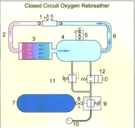
1-8 Schematic diagram of a closed circuit oxygen rebreather with a loop configuration and axial flow scrubber (1) Dive/surface valve with loop non return valves (2) Exhaust hose (3) Scrubber (axial flow) (4) Coun-terlung (5) Ovepressure valve (6) Inhalation hose (7) Breathing gas storage cylinder (8) Cylinder valve (9) Regulator first stage (10) Sub-mersible pressure gauge (11) Automatic make-up valve and (12) Man-ual bypass valve 1201 . . . . 38
1-9 Schematic diagram of electronically controlled closed circuit mixed
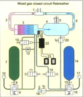
gas rebreather (1) Dive/surface valve and loop non-return valves (i.e. 'mouthpiece') (2) Exhaust hose (3) Scrubber (axial flow) (4) Counter-lung (5) Overpressure valve (6) Inhalation valve (7) Diluent cylinder
(8) Diluent cylinder valve (9) Absolute pressure diluent regulator (10)
Diluent submersible pressure gauge (11) Diluent manual bypass valve (12) Diluent constant mass flow metering orifice (13) Electronically
controlled solenoid operated oxygen injection valve (14) Oxygen cylin-der (15) Oxygen cylincylin-der valve (16) Oxygen regulator (17) Oxygen submersible pressure gauge (18) Bailout demand valve (19) Manual oxygen bypass valve (20) Automatic oxygen valve (21) Electronic con-trol and monitoring circuits (22) Primary and (23) secondary display units [20] . . . . 39 1-10 Henry Fleuss's rebreather system, the first commercially available
re-breather [15] . . . . 42
1-11 Double logarithmic plot of diving depth versus dive system endurance
for open circuit scuba, semi-closed and closed circuit rebreathers, and Advanced Diving Systems (ADS) . . . . 45 1-12 System flow circuit modeled in 1983 in Fortran by Sexton and Nuckols
[4 7] . . . . 4 6
1-13 Schematic of the 3 UBAs chosen for implementation from the 13
sug-gested using the Fortran model 149] . . . . 47 1-14 Recreational closed-circuit rebreather deaths by year 1998-2010 [261 . 49 1-15 Root cause analysis for diving fatalities [411 . . . . 53
2-1 Schematic view of the respiratory system [231 . . . . 61
2-2 Schematic view of the exhalation and inhalation processes 1231 . . . . 61
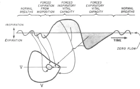
2-3 The shape of inhalation and exhalation processes from a pneumatogram [2 2] . . . . 6 2
2-4 A zoom into the breathing shape: the maximum velocity/volume loop;
the tidal volume can be determined from the vital capacity of the lungs using the inspiratory and expiratory reserve
122]
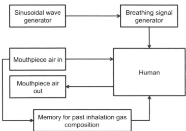
. . . . 63 2-5 Total lung capacity (TLC), vital capacity (VC) and residual volume(RV) in normal adult males 1221. The vital capacity is the most im-portant for diving. . . . . 63 2-6 The human module implemented in the rebreather analytical model . 65
2-7 The modeled breathing in and out signal . . . . 65 2-8 The oxygen evolution in the mouthpiece over one minute: inhalation
(blue) and exhalation (red) . . . . 67 2-9 The carbon dioxide evolution in the mouthpiece over one minute:
in-halation (blue) and exin-halation (red) . . . . 68
2-10 The water vapor evolution in the mouthpiece over one minute: inhala-tion (blue) and exhalainhala-tion (red) . . . . 68 2-11 The nitrogen evolution in the mouthpiece over one minute: inhalation
(blue) and exhalation (red) . . . . 69 2-12 The pressure evolution in the mouthpiece per the different gas
compo-nents for constant volume breathing . . . . 69 2-13 Pressure trend in the mouthpiece for a 10 liter confined volume: figure
shows the hypoxia and hypercapnia limits . . . . 70 2-14 The structure of the US Navy MK16 MODO rebreather analytical model 71
3-1 The MK16 MOD 0 closed circuit UBA 114] . . . . 76 3-2 Object Process Methodology functional decomposition of the MK16
MOD 0 closed circuit UBA 121] . . . . 76 3-3 The metabolic rate and depth profiles for a typical dive [141 . . . . . 79
3-4 Simulation of a typical bang-bang controller applied to a plant: the setpoint is given in red, the dynamics of the plant are shown in blue and the controller behavior is shown in green
[551
. . . . 83 3-5 A diagram of a PID controller in a feedback loop [561 . . . . 833-6 Comparison of open loop, bang bang (electronic) and constant mass injection (mechanical) control on a surface level, extreme work dive . 84
3-7 The schematic of the partial pressure of oxygen in the diaphragm
con-trol problem . . . . 85
3-8 The system identification dataset for the plant . . . . 86
3-9 The Bode plots for the plant . . . . 87
3-10 The step response for the PID controlled plant . . . . 87
3-11 Complexity measure for a graph. Control algorithms can be repre-sented as graphs and their complexity is calculated using McCabe's cyclomatic complexity algorithm [62] . . . . 88
3-12 Oxygen tank endurance for various control types applied to the human breathing m odel . . . . 88
3-13 Oxygen tank endurance for various control types applied to the human breathing m odel . . . . 89
3-14 Control can extend the endurance of closed-circuit rebreather systems: 1000 minutes instead of the typical 170 minutes . . . . 89
4-1 Effect of varying the diver metabolic rate on the oxygen tank pres-sure (we see changes in slope: steepest slope corresponds to extreme work regime, shallowest to rest) and the overall diaphragm pressure (maintained despite metabolic rate variations) . . . . 92
4-2 Decomposition of total diaphragm pressure from Figure 4-1 in major constituent partial pressures: oxygen and nitrogen . . . . 93
4-3 The correlation of depth and total external pressure for a typical dive 94 4-4 The decomposition of diaphragm total pressure in oxygen and nitrogen partial pressures during the dive profile shown in Figure 4-3 . . . . . 95
4-5 The usage of the oxygen and nitrogen tanks as a function of the depth of the dive . . . . 95
4-6 Diaphragm pressure adaptation shown in a typical diving profile: vari-able metabolic rate and varivari-able depth . . . . 96
4-7 Oxygen tank normal functionality: it injects mass to the diaphragm to
maintain the oxygen partial pressure to the set limit . . . . 98
4-8 Oxygen tank failure . . . . 99
4-9 Low oxygen tank starting pressure . . . . 100
4-10 Scrubber failure . . . . 101
4-11 Scrubber low yield 30% . . . . 102
A-1 Schematic of the rebreather analytical model and its constituent modules107 C-1 Snapshot of the implementation for the human breathing process in MATLAB Simulink . . . . 175
C-2 Snapshot of the implementation for the exhalation mouthpiece in MAT-LAB Sim ulink . . . . 176
C-3 Snapshot of the implementation for the carbon dioxide scrubber in MATLAB Simulink . . . . 177
C-4 Snapshot of the implementation for the diaphragm in MATLAB Simulink178 C-5 Snapshot of the implementation for the inhalation mouthpiece in MAT-LAB Sim ulink . . . . 179
List of Tables
1.1 No decompression dive table, sources: PADI, NAUI, NOAA and US N avy [181 . . . . 36 1.2 Recreational closed-circuit rebreather deaths by stated cause; note the
large number of cases in which there is scant information; in many other cases, while a cause of death is given, little evidence is available to corroborate that analysis 1261 . . . . 51 1.3 Comparison of fatality rates of various high-risk sports
126]
. . . . 51 2.1 Breathing rate and the corresponding total ventilation 122] . . . . 64 2.2 Inhalation and exhalation components by partial pressure in a 760mmHgtotal pressure 1221 . . . . 64
Abbreviations
ABS ADS BCD BOL BOV BSAC CCOUBA CCR CMI CO2 DAN DCS eCCR EOL FMECA FPE fsw LED mCCR MSE msw NAUI NOAA OC OPM PADI PID RBW RMV RQ SAC SCR SITS SPECWAR STPA UBAAcrylonitrile, Butadiene, Styrene Advanced Diving System
Buoyancy Control Device Beginning of Life
Bail-Out Valve
British Sub-Aqua Club
Closed-Circuit Oxygen Underwater Breathing Apparatus Closed-Circuit Rebreather
Constant Mass Injection Carbon Dioxide
Divers Alert Network Decompression Sickness
Electronically-controlled Closed Circuit Rebreather End of Life
Failure Modes, Effects and Criticality Analysis Final Prediction Error
feet seawater
Light - Emitting Diode
Mechanically-controlled Closed Circuit Rebreather Mean Squares Error
meters sea water
National Association of Underwater Instructors National Oceanic and Atmospheric Administration Open Circuit
Object Process Methodology
Professional Association of Underwater Dive Instructors Proportional - Integral - Derivative
Rebreather World
Respiratory Minute Volume Respiratory Quotient
Surface Air Consumption
Semi-Closed Circuit Rebreathers Scientist in the Sea Program Naval Special Warfare Forces
System Theoretic Process Analysis Underwater Breathing Apparatus
Chapter 1
Introduction
Underwater - the other two thirds of our world - is a fascinating place. There are a lot of activities to do under the water, from photography, seeing fish and other critters up close, exploring new places or seeing historic shipwrecks
11]
to rescue/sal-vage missions, submarine repair missions or diving research/development [2]. Diving equipment allows us to visit the underwater world by making it possible to breathe, see and move comfortably under the surface. Gear helps us transform from land-dwellers to somewhat similar to aquatic beings, even for a short while. A mask helps us see clearly, the scuba regulator and gas tanks provide the air we need, fins allow us to swim efficiently and the wetsuit helps maintain our body temperature and stay warm. The diving equipment varies in function of the environment we want to dive in: tropical scuba equipment is for warm water temperature (240C/750F and up),temper-ate scuba equipment is for diving in modertemper-ate temperature (cooler than 240C/75 F),
cold water scuba equipment covers water temperatures cooler than 15'C/60'F and the technical diving equipment, used by very experienced, highly trained divers to visit environments beyond the limits of recreational diving
131.
We can classify diving equipments in two broad categories, depending on how the breathing gas is used: open circuit and rebreather systems. Typically, for recre-ational purposes and when the diver is not a technical diver, (s)he will use an open circuit scuba equipment. The diver inhales gas from the tanks and exhales it to the surrounding environment (shown in Figure 1-1)
[3].
Figure 1-1: Open circuit scuba system: the diver inhales air from the tanks and exhales it to the surrounding environment
[3]
'1Q hlJ
Li
]
OvrPessuwe
Figure 1-2: A rebreather system and its components [5]
Rebreathers reuse the gas we exhale by recycling the good part and replenishing it from the gas tanks for the next breath. The system also features a carbon dioxide scrubber for removing the carbon dioxide from the diver's exhaled breath. This
open circuit diving, a huge benefit that allows longer dives. Another advantage is the quiet factor: since rebreathers do not vent gas to the environment, no bubbles are formed during diving so we can approach marine animals that would normally shy
away from bubble noise. Additionally, because we breathe gas that has been warmed by us and by the recycling process (specifically the absorption of carbon dioxide in the scrubber), rebreather diving keeps us warm, which is a bonus in cool water
[4].
There are two rebreather types:" Closed-Circuit Rebreathers (CCRs) - these systems recycle all the air we exhale, only a few bubbles escape during ascent to release the expanding gas. These systems require two gas supplies: a diluent (air, nitrogen or helium, depending on the depth we are diving at) and oxygen
* Semi-Closed Rebreathers (SCRs).
Figure 1-2 shows a rebreather system components:
" Counterlung, also called a diaphragm, is an expandable bag that expands when we inhale
" Valves, that direct the air circulation from our mouth through the breathing assembly (also called the exhalation mouthpiece) to the carbon dioxide scrubber, to the diaphragm for gas makeup and then back through the inhalation part of
the breathing assembly (also called the inhalation mouthpiece)
* Mouthpiece - closes and also connects the Bail-Out Valve (BOV), which is an open-circuit second stage regulator connected to a cylinder with breathing gas for emergencies
* Gas supply - feeds into the gas flow to replenish the oxygen we consume during diving and also increases the diaphragm volume as needed for buoyancy
" Oxygen sensor(s) and control system - located behind the gas cylinder; mea-sure the oxygen partial presmea-sure in the breathing gas, which is then fed to the
partial pressure we need for the depth and metabolic rate that we are at and adjusts in accordingly
* Head-up display (HUD) -displays the consumables states in the system (battery state, gas tank pressure, carbon scrubber duration).
After introducing these basic diving concepts, we will present the thesis objective and outline in Section 1.1. Then we will review the motivation and background for
the problem we are studying in this thesis, as well as a literature review of previous efforts in this field.
1.1
Thesis objective and outline
The focus of this thesis is on life support systems, specifically air revitalization loops that keep humans alive in harsh environments, such as deep in the oceans or far out in the unwelcoming vacuum of space. Both astronauts and rebreather divers need a specific gas combination at set pressures in order to explore and work in those environments and we use similar systems for these tasks. We have chosen to study, model and simulate a unified system configuration that can be used both for Earth and Space applications. We briefly presented its configuration in Figure 1-2. In the spacesuit, the rebreather is integrated in the life support equipment backpack, shown in Figure 1-3.
On Earth, as well as in space, we would like to extend our exploration time and keep the equipment weight to a minimum, because the effort to carry it would be a burden to the explorer. In order to do this, we need to study other methods to control the oxygen gas addition in the diaphragm. On one hand, there are systems that automatically dose the oxygen, irrespective of the diver's activity. These systems have been shown as being wasteful in their oxygen dosage, and the diver is exposed to oxygen toxicity issues or hypoxia [52]. On the other hand, there are manual oxygen dosing systems, that are heavily prone to failures as shown in Section 1.3.3. Therefore,
Caution and Warning Computer Primary Oxygen Tanks Contaminant Control Cartridge Battery -Lower Torso Assembly Fan/Separator/ Pump/ Motor Assembly Water Tank Portable Life S pport System Secondary Oxygen Tanks TV Camera Lights Helmet Communlcations Cartier Assembly Torso In-Suit Drink Bag Temperature Control Valve Gloves Liquid Cooling and Ventilation Garment
Figure 1-3: A spacesuit - the rebreather system is integrated in the backpack [61
systems that automatically dose the oxygen and adapt this dosage as a function of
diver activity are preferred and these are what we are studying here. The research questions we are looking into are the following:
1. What configurations of air revitalization systems (gas tank sizes and gas con-trol methods) can achieve a specified mission endurance, where endurance is defined as the lifetime of the mission?
2. What is the maximum endurance that an air revitalization architecture can achieve, given a set gas tank size?
3. How does the tradespace of mission endurance versus the gas control method look like?
We aim to answer the questions above using an analytical model of an air
revi-talization systems, particularly a rebreather, that we will model and simulate in this thesis.
The hypothesis we are investigating is that more advanced control methods will help increase the oxygen endurance for a fixed gas tank size.
The thesis starts with Chapter 1, containing the motivation, then we introduce
the reader to diving, its effects on the human body and then explain why we need
life support systems when diving and what are their main tasks. We then present the evolution of rebreather systems over time, what analytical models have been developed and the problems that these systems have experienced during diving, as shown in accident reports.
Chapter 2 illustrates how we constructed the analytical model presented in this thesis. The main challenge was to develop an accurate model of the human breathing process. The human body does it unconsciously, but we explained how we translated this into computer language and the associated assumptions Section 2.1. Then we present the structure of the model and the problem statement in Chapter 2.
We then particularize the generic model we build in Chapter 2 in Chapter 3. We state the assumptions that serve to transform the generic model into a model of the US Navy MK16 rebreather, then, in the following Section, we describe the model components. The Chapter ends by showing several strategies for maximizing oxygen duration documented in the literature and presents the application of some of these on the model developed in this thesis. It also answers the research questions and investigates the tradespace formed by the mission endurance and control complexity. In Chapter 4 we present advanced applications of the MK16 rebreather model: we vary the diver metabolic rate and the depth at which the system operates and analyze the results. We also show how the model can be used to reconstruct some of the most frequent diving accidents involving rebreathers.
This thesis ends with Chapter 5, where we draw the conclusions and underline the most important points of the analytical model developed in this thesis, as well illustrate the open issues subject to future work. Figure 1-4 summarizes the thesis chapters and their contents.
Introduction, diving background Chapter 1 Thesis motivation
Literature review
Rebreather analytical model dev
Chapter 2 Human breathing modeling Model structure and components Problem statement
Advanced applica the analytical mod Chapter 3 Chapter 4 simulation of var
diving depth and
Application of analytical model rate
to MK16 case study Rebreather accide
Model assumptions simulation
Problem solution
Chapter 5 Conclusions and future work Thesis summary
Appendices Code structure and MATLAB Bibliography Simulink code of the analytical
rebreather model clopment tions of el: able metabolic ,its
Figure 1-4: Thesis outline
1.2
Motivation and background
Although diving or traveling into space does not need a long motivation list, we need to be aware of the risks and dangers that the human body might face when performing these activities. This keeps us safe and helps us enjoy these activities even more!
The model that will be built in the next chapters is that of a generic ventilation and air revitalization loop for space and Earth applications, but in the next chapters we will use the unified term of a rebreather model to describe it, while keeping in mind its generality and multiple application range.
This Section starts off by introducing basic diving concepts, such as pressure, buoyancy, shows us how to calculate the necessary air for a dive. We then present the effects diving has on the human body and we give the acceptable ranges for oxygen,
carbon dioxide and nitrogen during a dive. Having reviewed all this, we will then explain the necessity of life support systems while diving and present a short history of their development.
1.2.1
Diving basic concepts
In order to build an analytical model of a diver's equipment, we need to understand the main forces and challenges that divers encounter underwater, presented in the next subsections.
Pressure
This Section looks at how pressure changes underwater and reviews the funda-mentals of pressure and scuba diving.
Pressure increases with depth: the deeper a diver descends, the more pressure the water above him/her exerts on the diver's body. The pressure a diver experiences is a sum of the pressures above him, both of the water and the air. Most pressures in scuba diving are given in a unit called ata, used in place of the atmosphere (atm) to indicate that the pressure shown is the total ambient pressure on the system. For example, an underwater pressure of 3.1 ata would mean that the 1 atm of the air above the water is included in this value. Additionally, every 10 meters (33 feet) of salt water exert 1 ata of pressure
[7].
The water pressure will compress the air: the air in a diver's body air spaces and gear will compress as the pressure increases (and expand when pressure decreases). Air compresses according to Boyle's law:
pV = constant (1.1)
This law states that as the pressure changes, the volume of the gas in the diver's body and soft equipment changes too. As the diver descends, the increase in pressure causes the air in the body's air spaces to compress. The air spaces are for example the ears, mask and lungs feel like vacuum because the compressing air creates a negative
pressure. This can cause delicate membranes, like the ear drum, to be sucked into these air spaces causing pain and injuries. On ascent, the reverse happens: the air
spaces expand as a consequence of decreased pressure. The air spaces in the lungs and the ears of the diver experience a positive pressure as they become overfull of air. If the diver does not breathe properly under water, this process could burst his/her ears or lungs.
In order to prevent a pressure related injury, divers must equalize the pressure in their body's air spaces to the pressure around them. To equalize the pressure in the
diver's air spaces on descent, the diver adds air to his body airspaces to counteract the "vacuum" effect (this can be done by breathing normally, as this adds air to the lungs, adding air to the mask by breathing out of his nose or adding air to the ears and sinuses using pressure equalization techniques). During ascent, the diver needs to release air from his airspaces, because the ambient pressure decrease causes the air
to feel as if it has too much volume (this can also be done by breathing normally and allowing the body to eliminate the extra air from the lungs and by ascending slowly and allowing the extra air in the diver's ears, sinuses and mask to bubble out on their
own).
Buoyancy
Buoyancy is an object's tendency to float. In scuba diving, the term is used not
only to describe the diver's tendency to float, but also the tendency to sink or do neither in the water [9]:
" Positive buoyancy or positively buoyant - the object or person floats upwards in the water or remains floating on the surface
" Negative buoyancy or negatively buoyant -the object or person sinks downwards in the water or remains on the bottom
" Neutral buoyancy or neutrally buoyant - the object or person neither sinks downward nor floats upward, but remains suspended at a single depth in the
Buoyancy can be defined as the net pressure acting on an object due to the fact that the object has displaced a certain amount of water: this water has the tendency of filling the space that the object now occupies, thus exerting a force and pressure
on that object. This force is pushing the object upward and it is called the buoyant force. A schematic representation of this is shown in Figure 1-5.
Figure 1-5: A schematic representation of buyoancy and gravity [171
In order to determine if an object will sink or float, we can apply Archimedes's principle: if the object's weight is greater than its buoyancy, then it will sink;
oth-erwise, it will float, and if the two forces are equal then it will maintain its depth in the water. In diving, we want to sink to a certain depth, maintain it for the duration
of the dive and then slowly resurface. This implies that we need to control our buoy-ancy. Since our bodies displace a fixed amount of water, we need an external device
to help control the buoyancy: this is an inflatable jacket called the buoyancy control device (BCD). In general, however, the diver, the gear and the BCD (even with no air inside it) are positively buoyant, so the diver needs to carry weights with him to
Calculating the air consumption rate
The air consumption rate is the mass flow rate at which the diver uses his/her air. Air consumption rates are given in the amount of air the diver breathes in one minute at the surface. There are two different methods of measuring air consumption in scuba diving: the Surface Air Consumption (SAC) rate and the Respiratory Minute Volume (RMV) rate [101.
It is useful to know the air consumption rate in scuba diving for three main reasons:
" Dive planning -the diver can use his/her air consumption rate to calculate how much time he can stay underwater at the planned depth and to determine if (s)he has enough gas to make the return trip. The air consumption rate is also useful in determining the required reserve tank pressure for a dive. It is often surprising for divers to see that the calculations indicate that more than the standard 700-1000 psi of reserve pressure may be required to get a buddy team safely to the surface. When decompression stops are made, the air consumption rate is critical in determining how much gas to carry for these stops
1101
" Determining stress or comfort level - the air consumption rate is a great tool to gauge the diver's stress or comfort level: if, during a dive at 45 feet the diver notices that (s)he used 500 psi when the typical air consumption rate for 5 minutes of diving at that depth is 200 psi, then this is an indication that something is wrong
" Identifying equipment problems - a diver who has a major leak may notice that the air consumption rate is unusually high although his/her breathing rate is normal. For example, an increased air consumption rate may be an indication that a diver's regulator may require servicing, as the breathing resistance (and so the air consumption rate) increases when a regulator requires servicing. In short, an example of different air usage at various depths is illustrated in Figure 1-6.
AIR
BAR DEPTH VOLUME
A diver uses 2 Bar /minute at the
surface
He will use 2 x more air at 10m (the air
is 2 x more dense). So he breathes 4 Bar / minute at I Om
He will use 3 x more air at 20m. So he
breathes 6 Bar / minute at 20m
He will use 4 x more air at 30m. So he breathes 8 Bar / minute at 30m
He will use 5 x more air at 40m. So he breathes 10 Bar / minute at 40m
Figure 1-6: Example of an air consumption scenario during a dive [161
Additionally, the amount of air a diver has can be modified by the tank's
sur-rounding temperature, as described by Gay-Lussac's second law: as the temperature
increases the pressure of the air in the diving cylinder increases. This is why a diver
who enters the cold water with a warm diving cylinder, for example after a quick re-fill, will find that the pressure of the cylinder drops by an unexpectedly large amount during the early stages of the dive, when the cylinder cools down.
Calculating the surface air consumption (SAC) rate
The SAC rate is a measure of the amount of breathing gas that a diver consumes
in one minute at the surface. This rate is given in units of pressure (bar or psi).
In order to determine this rate, divers will measure their starting pressure (the pressure of the air in the tank after it has been immersed in water and had a chance
to cool down) and their end pressure after swimming for 10 minutes at a depth of 10 meters. Although the rate calculated by using this method will be reproducible, it
is advisable that divers plan their dives conservatively, by taking into account that the real conditions may be very different from the test conditions. The formula to
calculate this rate is the following
[81:
{[(Pstart - Pend) * 10] + (d + 10)} + t = SAC (1.2)
where Pstart is the pressure in bar in the tank at the beginning of the test period, Pend is the pressure in bar in the same tank at the end of the test period, d is the average depth during the dive or the depth of the dive maintained during the test period and the t is the time in minutes is the diving time or the test period time.
SAC is measured in bar/minute.
Because SAC rates are given in terms of tank pressure and not volume of air, SAC rates are tank specific:
* 500 psi of air in a standard 80 cubic foot tank correspond to 13 cubic feet of air
* 500 psi of air in a low pressure 130 cubic foot tank correspond to 27 cubic feet of air
therefore, a diver that breathes 8 cubic feet of air per minute will have a SAC rate
of 300 psi/minute when diving with a standard aluminum 80 cubic foot tank and a SAC rate of 147 psi/minute when diving with a low pressure 130 cubic foot tank. Because SAC rates are not transferable between different tank sizes, the diver should first calculate its respiratory minute volume (RMV) rate, which is independent of the
tank size. The diver then converts the RMV rate to a SAC pressure based on the and working pressure of the tank (s)he plans to use during the dive [81.
Calculating the respiratory minute volume (RMV) rate
The RMV rate is the measurement of the volume of breathing gas that a diver consumes in one minute at the surface. It is expressed in liters per minute or in cubic feet per minute. Unlike a SAC rate, the RMV rate is tank independent: a diver
who breaths 8 cubic feet of air per minute will always breathe 8 cubic feet of air per minute, regardless of the tank size used. For this reason, divers remember their air
consumption rate in RMV format, and then convert it to bar or psi based on the type of tank to be used. In order to obtain the RMV rate, we simply multiply the SAC rate with the volume of the tank, in liters:
RMV = SAC - Vank (1.3)
For example, a diver who has a SAC rate of 1.7 bar/minute when diving with a 12 liter tank has an RMV rate of 12 x 1.7 = 20.4 liters/minute.
Having determined the SAC and RMV rates, in order to calculate how much time the air supply will last on a dive we need to calculate the pressure at a particular depth d, (in ata). The depth d is given in meters.
p= (d - 10)+1 (1.4)
Multiplying the SAC rate with the pressure will give the air consumption rate at that depth:
air consumption rate = SAC - p (1.5)
The next step is to determine the available pressure: from a full tank we need to determine at which pressure you want to begin ascent (called the reserve pressure). The difference between the full tank pressure and this reserve pressure will give the available pressure. With this we can now determine how long the air in the tank will last at that depth as:
time the air will last = Pavailable gas + air consumption rate at that depth (1.6)
In order to determine the RMV and SAC rates and how long the air supply will last during a dive, we follow these five steps:
1. Determine the SAC rate for the tank we plan to use:
rate calculations will be as follows: for an 80 cubic foot tank with a 3000 psi
working pressure the tank conversion factor is 0.0267:
SAC rate = 0.67 + 0.0267 = 25 psi/minute (1.7)
For an 130 cubic foot tank with a 2400 psi working pressure the tank conversion factor is 0.054:
SAC rate = 0.67 + 0.054 = 12.4 psi/minute (1.8)
2. Determine the pressure at which we will diving:
Using the following formulas we can determine the pressure in atmospheres (ata) experienced at different depths in salt and fresh water:
* In salt water:
pressure = (depth in feet + 33) + 1 (1.9)
9
In fresh water:pressure = (depth in feet + 34) + 1 (1.10)
For example, if we descend to 66 feet in salt water we will experience a pressure
of 3 ata.
3. Determine the air consumption at the planned depth: In order to do this we apply the following formula:
SAC rate - pressure = Air consumption rate at depth (1.11)
will use:
Air consumption rate C 66 feet = 25 psi/min - 3 = 75psi/min (1.12)
4. Determine how much air we have available: first, check the tank pressure to de-termine our starting pressure, then dede-termine the pressure at which we would like to begin our ascent (reserve pressure) and finally subtract the reserve pres-sure from the starting prespres-sure
Starting pressure - Reserve pressure = Available pressure (1.13)
For example if our starting pressure is 2900 psi and we want to begin our ascent with 700 psi then the available pressure is 2200 psi.
5. Find out how long the air will last: divide our available gas by the air consump-tion rate at our planned depth
Time air will last = Available gas - Air consumption rate depth (1.14)
If our available pressure is 2200 psi and the air consumption rate is 75 psi/minute at our planned depth then the air will last:
2200 psi + 75 psi/minute = 29 minutes (1.15)
Two other physics laws of relevance to diving are Dalton's law and Henry's law. Dalton's law states that in a mixture of breathing gases, the concentration of individ-ual gas species in the mix is proportional to their partial pressure. Partial pressure is a very useful way we can express limits for avoiding oxygen intoxication or carbon dioxide toxicity, as presented in the next subsection.
1.2.2
Effects of diving on the human body
Like any experiences, diving has its risks. The extreme pressures involved can take a toll on the fragile human body if not handled appropriately. The most impor-tant medical conditions involved with diving are decompression sickness and nitrogen narcosis. These are explained in the next sections [11J.
Decompression sickness
Decompression sickness, also known as the bends or Caisson disease, is an illness that can affect divers or miners -in general people who are exposed to rapid external pressure changes. It is caused by the build up of nitrogen in the body: as we breathe, we inhale about 79% of nitrogen in the air. As a diver descends, this nitrogen is absorbed in the body tissues. The problem is when the diver ascends and the lowered pressure causes the nitrogen in the blood to come out of the solution. If the diver ascends too quickly, the nitrogen escapes at a fast rate and can cause bubbles, that can transfer to the arterial blood circulation and block the blood flow to areas like the lungs, brain and other essential areas of the body. This is why divers must ascend slowly, to give their bodies time to eliminate this nitrogen through normal breathing. If the diver spent a longer time under the water than the no-decompression limit (this is a time limit that refers to the maximum time a diver can spend underwater and ascend to the surface without decompression stops along the way), then decompression stops are mandatory. Please refer to Section 1.2.2 for diving tables explanations and examples.
The treatment for DCS consists of oxygen administered on site and first aid, followed as soon as possible by recompression treatment in a recompression chamber.
Nitrogen narcosis
Nitrogen narcosis is a state of altered awareness caused by breathing a high par-tial pressure (or concentration) of nitrogen. The deeper a diver goes, the higher the partial pressure of nitrogen and other gases will be. This will usually limit the depth
a diver can go to. Once the nitrogen narcosis sets in, the diver should ascend at a safe rate in order to reduce the partial pressure of nitrogen in the air (s)he is breath-ing. Thirty meters is the average depth at which divers start to experience nitrogen narcosis.
Narcosis has been called "the rapture of the deep" and many divers compare it to a pleasant state of drunkenness. Some divers use the "Martini rule" to roughly estimate the effects of narcosis during a dive: this rule states that for every increment of 18 meters depth, a diver experiences the narcotic effect of drinking one Martini. At depths of 60 meters divers are likely to experience severe narcosis and even
un-consciousness.
Hyperoxia and hypoxia
Hyperoxia is the result of breathing an excessively high partial pressure of oxygen. Oxygen toxicity is a catastrophic hazard in diving, as the seizures caused can result in near death by drowning
[121.
The seizures occur suddenly and with no warning signals. As there is an increased risk of oxygen toxicity on deep dives, long dives or dives in which oxygen-rich gases are used, divers calculate a maximum operating depth for the air mixture that they are using, and the cylinders used are clearly marked with this maximum depth[13].
Diving below 56 meters on air only would expose the diver to oxygen toxicity, as the partial pressure of oxygen exceeds 1.4 bar, so a gas mixture has to be used that contains less than 21% oxygen. Augmenting the nitrogen content of the gas is not a good solution, because it would lead to nitrogen narcosis. This problem is solved by adding helium, which is not narcotic - nitrogen can be completely replaced with helium, and the resulting mix is called heliox, or by replacing a part of nitrogen with helium, and the resulting mix is called trimix.The opposite of hyperoxia is hypoxia - a condition when there is not enough oxygen in the diver's ventilation circuit to meet metabolic requirements. If oxygen is not added to the ventilation loop, the existing oxygen will be consumed in 2-5 minutes and the remaining gas mixture is not capable to sustain life
1141.
The maximum oxygen partial pressure at sea level is 120 kPa and the minimum is 10 kPa.Hypercapnia
Hypercapnia is a condition caused by abnormally elevated levels of carbon dioxide
in the blood. This can be prevented by scrubbing the carbon dioxide from the air in the rebreather system. However, monitoring the partial pressure of CO2 is
impor-tant to make sure that the CO2 scrubbing equipment is functioning normally. The
maximum carbon dioxide partial pressure is 2.93 kPa, the equivalent of 22 mm Hg
[1.
Diving tables
In order to avoid decompression sickness and other problems associated with
resid-ual nitrogen, divers use dive tables. They are called no-decompression dive tables and they tell divers how long they can stay underwater at a certain depth or, conversely, how deep they can go for a certain amount of time. The most commonly used dive tables are from the Professional Association of Underwater Dive Instructors (PADI), National Association of Underwater Instructors (NAUI), National Oceanic and At-mospheric Administration (NOAA) and the US Navy. Table 1.1 shows some of the depths and time limits from this sources. The NOAA and Navy tables are similar, as shown below, and are based on research done over the last several decades by the Navy, primarily with military divers. NAUI and PADI use tables that are slightly
more conservative than the Navy's and are specifically oriented towards the sports diver [181.
Note that the table below suggests that there is no time limit when diving at depths less than 20 ft. (6.1 in). While theoretically correct, the practical limit is
about six hours.
A typical dive table is shown in Figure 1-7. all of these tables employ the concept of a letter group, which is a relative indicator of the amount of residual nitrogen in the body. The different tables use a different number of letter groups, but all start
at A. Letter groups closer to the beginning of the alphabet indicate lower levels of residual nitrogen.Second, each standard table is comprised of three parts
[18]:
Depth Depth NOAA and US NAUI table PADI table
(ft) (m) Navy diving table
0 - 20 0 - 6.1 No limit No limit No limit
21 - 40 6.4 - 12.2 200 min. 130 min. 140 min
41 - 50 12.5 - 15.2 100 min. 80 min. 80 min.
51 - 60 15.5 - 18.3 60 min. 55 min. 55 min.
61 - 70 18.6 - 21.3 50 min. 45 min. 40 min.
71 - 80 21.6 - 24.4 40 min 35 min. 30 min.
81 - 90 24.7 - 27.4 30 min. 25 min. 25 min.
91 - 100 27.7 - 30.5 25 min. 22 min. 20 min.
Table 1.1: No decompression dive table, sources: PADI, NAUI, NOAA and US Navy
[181
* Table 1 - End-of-Dive Letter Group: Shows the time and depth limits for no-decompression dives. Indicates the Letter Group at the end of the dive based upon the dive profile of the current dive, including the level of residual nitrogen
from previous dives.
* Table 2 - Surface Interval Timetable: Defines a new Letter Group after the planned surface interval. The new Letter Group will be the same as, or lower
than, the Letter Group before the surface interval.
" Table 3 - Repetitive Dive Timetable: Indicates the Adjusted Maximum Dive Time (AMDT) and Residual Nitrogen Time (RNT) for the next dive, based upon the current Letter Group 1181.
1.2.3
Life support systems for diving
A rebreather is a breathing device that absorbs the carbon dioxide from the hu-mans exhaled breath and allows the rebreathing (recirculating) of the unused oxygen in the air. Oxygen is added to this loop to replenish the amount metabolized by the
user. The rebreather is different from the open-circuit breathing apparatus, in which the exhaled gas is passed to the environment (described in Section 1.2). Rebreather
technology is used in a wide variety of areas: in space (when the oxygen supply is lim-ited and the external environment (vacuum) is not able to support life), in firefighting
AL NITROGEN TIME SDIVE TIME NITROGEN TIME TO U) 12 15 18 21 24 27 30 33 36 40 Nw 40 50 6 70 80 90 100 110 120 130 " ts 7 6 5 4 4 3 3 3 3 3 117 131119 6 7 6 ? B 113, 67 44 36 V IS 15 C 13 25 70 2 4 20 j18j 113 112111
1
p0 49 38 30126 23 20 118 16 15 13 81 42 25 19 12 4 Wa 47 31 29 24 22 20 15 16 mISI14 ? 1 73156 44137 32129128 24 21 19 87 56 52 43 30 33 30 27 25 22 01 34zor
4 K L TABLE 3: REPETITIVE DIVE TIMETABLE.SLAC UPPE) NUMBERS ARE RESIDUAL NITROGEN TIE (RT)
2 Denc. 2000 10000 RED (LOWER NUMBERS ARE ADJUSTE MAXIMUM DIVE TIMES (AuG71 26l 17 15 1 ofI l 454 is-, 111 188 17 11153 11 10 W AVOID REPETITNE ONES OVER 1W (301 E F G
TABLE 1: END-OF-DIVE LETTER GROUP START
DEPT MAXIMUM DIVE M60 DIVE TIME REQUIRING OSCOMPRESSION
DIVE TABLES Adapted from NAUI Tables by
G.C. Kessler
TABLE 2: SURFACE INTERVAL TIME (SIT) TABLE TIMES LITED IN HOURS:MSIUTES ACTUAL DIVE TIME SHOULD NOT EXCEED THIS VALUE
Figure 1-7: Example of a NAUI diving table [181
(where the environment is toxic) or in hospitals (where it is used by a patient under anesthesia to supply the concentrated gas to the patient without contaminating the air the medical staff breathes).
Different rebreather types are shown in Figures 1-8 and 1-9. The rebreather con-figuration that the model developed in this thesis is based upon will be discussed in
Chapter 3.
In an oxygen rebreather, like the one shown in Figure 1-8, the diver exhales into a
bag (called a 'counterlung' (4)). A scrubber (3) removes the carbon dioxide and fresh gas is added to replace the metabolized oxygen (11). This recycled gas in inhaled
again by the diver. In the case of a pure oxygen rebreather, the breathing gas contains mainly oxygen, and the partial pressure of oxygen in the circuit is dependent on the
M FT M TIE 13011 1 NO. MINUTES REQUIRED AT 1W ( M) STO 12 40 5 15 25 30140 50 70 80 100 110 1 15 50 10 15 25 30 40 50 60 70 1860 10 15 2025 30 405055 21 70 5 10 15 20 30 35 40 45, 24 80 5 10,15 20 25 30 35 s 0 27 90 5 10 12 15 20 25 30100 5 7 10 15 20 22 - * 33105 10 j13 1CIS 36120 5 10 2 _ 25 5 A B C D E F G H I J K L M.00 . 24:00 :00 400 4:00 4:00 00 :00 :00 4:00 00 100321 4:50 5A9 6:35 7:0 7361 & 822 8:51 859 91 320 4:49 5&A 6:34 7:0 735 75 821 :0 8:58 912 _QLI 140 A 325 M426 4W 5 13 &41 5:49 :W 1:39 2:36 3-24 37 425 4:4 5:12 5:40 5:48 6:02 0-10 1:10 1:5 2:59 :1. 3:44 4 4:20 4: 139 1:57 228 25 3:20 3:43 4:02 419 4:31 0:54 129 1:59 223 2:44 3:04 3:21 3:36 0:10 0:46 1:16 1:42 2:03 221 239 2: 0A5 1:15 1.41 12: 2:38 2 0:10 1k37 100 120 1:36 110 - 0 0:59 t 13521 0:10 0:34 9:58 1:121 12 ____________________________________0:33 Wig4 1:11 1.26 0:10 .3 :50 1.0 1I3 0:49 1:06 :10 0:29 0:4 0:10 9:27 RNT RESI +AR ACTUAl TNT TOTAL (USE THIS FIGURE DETERMINE END-( DIVE LETTER GRI
M. FT. ",@VMS .. &..I , . -q3f ^^ 10 C 50 43 I834 31 2! 25 I ei
Figure 1-8: Schematic diagram of a closed circuit oxygen rebreather with a loop configuration and axial flow scrubber (1) Dive/surface valve with loop non return valves (2) Exhaust hose (3) Scrubber (axial flow) (4) Counterlung (5) Ovepressure valve (6) Inhalation hose (7) Breathing gas storage cylinder (8) Cylinder valve (9) Regulator first stage (10) Submersible pressure gauge (11) Automatic make-up valve and (12) Manual bypass valve [201
ambient pressure. This rebreather type maximized the efficiency of gas usage and provides a bubble-free, silent diving capability useful in military applications. Due to the fact that the carbon dioxide absorption in the scrubber (3) is an exothermic
reaction, the air is warmed by the heat and so the diver breathes warm, humid gas. The presently recommended oxygen partial pressures for maintaining life range from
0.1 bar (10.1 kPa) to 1.6 bar (162 kPa). A partial pressure above this upper limit may lead to acute oxygen toxicity, manifested by epilepsy-like convulsions, which is fatal underwater. A PPO2 under this limit will lead to unconsciousness.
Rebreathers are classified into either semi-closed circuit rebreathers (SCR) or man-ually or electronically controlled closed-circuit rebreathers (mCCR or eCCR). In a
SCR, oxygen enriched gas is pumped through a constant flow injector into the cir-cuit, typically at 6-12 bar L/min to substitute the metabolized oxygen. Excess gas in
the circuit is vented through an overpressure valve. The maximum depth that a diver can reach using this circuit is limited by the percentage of oxygen in the supply gas. In a CCR, the partial pressure of oxygen is kept at a constant level. In mixed-gas diving, the breathing gas in the CCR contains nitrogen or helium. To maintain a constant
Closed Circuit Oxygen Rebreather
2 4 5 6
Figure 1-9: Schematic diagram of electronically controlled closed circuit mixed gas rebreather (1) Dive/surface valve and loop non-return valves (i.e. 'mouthpiece') (2) Exhaust hose (3) Scrubber (axial flow) (4) Counterlung (5) Overpressure valve (6) Inhalation valve (7) Diluent cylinder (8) Diluent cylinder valve (9) Absolute pressure diluent regulator (10) Diluent submersible pressure gauge (11) Diluent manual bypass valve (12) Diluent constant mass flow metering orifice (13) Electronically controlled solenoid operated oxygen injection valve (14) Oxygen cylinder (15) Oxygen cylinder valve (16) Oxygen regulator (17) Oxygen submersible pressure gauge (18) Bailout demand valve (19) Manual oxygen bypass valve (20) Automatic oxygen valve (21) Electronic control and monitoring circuits (22) Primary and (23) secondary display units [20]
oxygen partial pressure, a control loop is needed. This loop contains electrochemical oxygen sensors, whose output is proportional to the partial pressure of oxygen; these are the sensor elements. In a mCCR, the diver manually adjusts the oxygen partial
pressure by adjusting the oxygen injection valve or adding oxygen manually. In an
eCCR, this task is usually performed automatically, by a microcontroller actuating a solenoid valve [431.
Both types of closed rebreather systems have many advantages:
* Gas efficiency: open circuit scuba diving has a gas efficiency of less than 5%
on the surface, to below 0.5% at 100 msw depth. In a CCR, because the gas is recycled, this gas efficiency reaches almost 100% and so the design of these
rebreathers is smaller and light-weight than OC scuba, but more complex
Mixed gas closed circuit Rebreather
2 3 4 5 6 22 114 7 23 10 17 15 9 16
" Silence: the CCR allows bubble-free operation, only during the ascent phase is
gas vented from the circuit
* Warm, humidified breathing gas is provided to the diver, due to the exothermal carbon dioxide absorption reaction in the scrubber. Cold breathing gas in cold water may lead to the regulator freezing; in a CCR this is avoided. The downside to operating a CCR in cold water is that the scrubber efficiency can be impaired.
1.3
Literature review
This Section presents a history of previous rebreather systems and previous efforts to create analytical models to analyze these systems. Here we present some of the characteristics of past rebreather models and that we will incorporate in this devel-opment process, shown in Chapter 3. The last part of this Section describes scuba and rebreather accident reports, which the model we are developing will simulate in Chapter 4.
1.3.1
Previous rebreather systems
Although diving was an activity we were interested in for many years (for ex-ample pearl divers), the first man to consider a self-contained underwater breathing apparatus was probably Giovanni Alfonso Borelli, a mathematician, in 1680. From that date onwards, numerous people were involved in the development of an Under-water Breathing Apparatus (UBA): Frederic de Drieberg, Klingert, Brize and Fradin, Abbe de la Chapelle just to name a few. Abata Felice Fontana (an Italian monk) and a Dutch physician Ingen Housz, were the first to investigate an UBA with 100% pure oxygen as breathing gas. It was William H. James in 1825 who probably put together the first design for a self contained underwater breathing apparatus. Early compressed oxygen cylinders were made of sheet copper and were formed with hemi-spherical ends, charged to a pressure of 30 atmospheres (441 lbs per square inch)
![Figure 1-1: Open circuit scuba system: the diver inhales air from the tanks and exhales it to the surrounding environment [3]](https://thumb-eu.123doks.com/thumbv2/123doknet/13991123.455127/18.918.286.595.111.398/figure-open-circuit-scuba-inhales-exhales-surrounding-environment.webp)