Publisher’s version / Version de l'éditeur:
Environmental Science & Technology, 49, 3, pp. 1964-1971, 2015-01-07
READ THESE TERMS AND CONDITIONS CAREFULLY BEFORE USING THIS WEBSITE.
https://nrc-publications.canada.ca/eng/copyright
Vous avez des questions? Nous pouvons vous aider. Pour communiquer directement avec un auteur, consultez la première page de la revue dans laquelle son article a été publié afin de trouver ses coordonnées. Si vous n’arrivez pas à les repérer, communiquez avec nous à PublicationsArchive-ArchivesPublications@nrc-cnrc.gc.ca.
Questions? Contact the NRC Publications Archive team at
PublicationsArchive-ArchivesPublications@nrc-cnrc.gc.ca. If you wish to email the authors directly, please see the first page of the publication for their contact information.
NRC Publications Archive
Archives des publications du CNRC
This publication could be one of several versions: author’s original, accepted manuscript or the publisher’s version. / La version de cette publication peut être l’une des suivantes : la version prépublication de l’auteur, la version acceptée du manuscrit ou la version de l’éditeur.
For the publisher’s version, please access the DOI link below./ Pour consulter la version de l’éditeur, utilisez le lien DOI ci-dessous.
https://doi.org/10.1021/es504888n
Access and use of this website and the material on it are subject to the Terms and Conditions set forth at
Kinetics of methane hydrate replacement with carbon dioxide and
nitrogen gas mixture using in situ NMR spectroscopy
Cha, Minjun; Shin, Kyuchul; Lee, Huen; Moudrakovski, Igor L.; Ripmeester,
John A.; Seo, Yutaek
https://publications-cnrc.canada.ca/fra/droits
L’accès à ce site Web et l’utilisation de son contenu sont assujettis aux conditions présentées dans le site LISEZ CES CONDITIONS ATTENTIVEMENT AVANT D’UTILISER CE SITE WEB.
NRC Publications Record / Notice d'Archives des publications de CNRC:
https://nrc-publications.canada.ca/eng/view/object/?id=651bacd6-2106-4c16-b524-40ccf4ee7034 https://publications-cnrc.canada.ca/fra/voir/objet/?id=651bacd6-2106-4c16-b524-40ccf4ee7034
Kinetics of Methane Hydrate Replacement with Carbon Dioxide and
Nitrogen Gas Mixture Using in Situ NMR Spectroscopy
Minjun Cha,
†Kyuchul Shin,
‡Huen Lee,
§Igor L. Moudrakovski,
∥,#John A. Ripmeester,
∥and Yutaek Seo*
,⊥†
Department of Energy and Resources Engineering, Kangwon National University, 1 Kangwondaehak-gil, Chuncheon-si, Gangwon-do 200-701, Republic of Korea
‡
Department of Applied Chemistry, Kyungpook National University, 80 Daehak-ro, Buk-gu, Daegu, Gyeongsangbuk-do 702-701, Republic of Korea
§
Department of Chemical and Biomolecular Engineering, Korea Advanced Institute of Science and Technology (KAIST), 291 Daehak-ro, Yuseong-gu, Daejeon, Chungcheongnam-do 305-701, Republic of Korea
∥National Research Council of Canada, Ottawa, Ontario K1A 0R6, Canada
⊥Ocean Systems Engineering Division, Korea Advanced Institute of Science and Technology (KAIST), 291 Daehak-ro, Yuseong-gu, Daejeon, Chungcheongnam-do 305-701, Republic of Korea
*
S Supporting InformationABSTRACT: In this study, the kinetics of methane replacement with carbon dioxide and nitrogen gas in methane gas hydrate prepared in porous silica gel matrices has been studied by in situ1H and13C NMR spectroscopy. The replacement process was monitored by in situ1H
NMR spectra, where about 42 mol % of the methane in the hydrate cages was replaced in 65 h. Large amounts of free water were not observed during the replacement process, indicating a spontaneous replacement reaction upon exposing methane hydrate to carbon dioxide and nitrogen gas mixture. From in situ13C NMR spectra, we confirmed that the replacement ratio
was slightly higher in small cages, but due to the composition of structure I hydrate, the amount of methane evolved from the large cages was larger than that of the small cages. Compositional analysis of vapor and hydrate phases was also carried out after the replacement reaction ceased. Notably, the composition changes in hydrate phases after the replacement reaction would be affected by the difference in the chemical potential between the vapor phase and hydrate surface rather than a pore size effect. These results suggest that the replacement technique provides methane recovery as well as stabilization of the resulting carbon dioxide hydrate phase without melting.
■
INTRODUCTIONGas hydrates are crystalline host−guest compounds composed of hydrogen-bonded networks of host water molecules and encaged guest molecules, such as methane, nitrogen and carbon dioxide.1 Recently, natural gas hydrates have received considerable attention because of their potential as a future energy resource.1−3Recent studies have focused on the efficient recovery of methane from natural gas hydrate deposits located offshore in marine sediments and under the permafrost in the Arctic region.4−7 However, exploiting methane from hydrate deposits as a fuel may result in increasing the concentration of CO2in the atmosphere, since currently methane is used mostly
as a fuel. From the perspective of the global carbon cycle, the sequestration of CO2needs to be considered, along with the
production of methane to avoid the portion of global warming that may be caused by anthropogenic CO2emission.
Recovering methane from the natural gas hydrate deposits through the injection of CO2into the hydrate layers, called the
replacement technique, has been widely studied as a promising option for producing methane and sequestering CO2
simultaneously.8−12 Recent studies include thermodynamic measurements, spectroscopic analysis, and molecular dynamic simulations to understand the replacement process. On the basis of13C NMR spectroscopic analysis, Lee et al. suggested
that the direct injection of carbon dioxide into methane hydrate layers could provide both methane gas recovery and CO2
sequestration with about 64% methane recovery.13 From a combination of thermodynamic studies and 13C NMR
spectroscopic measurement, Seo et al. estimated a replacement ratio of 67% when exposing methane hydrate to CO2.14Schicks
et al. observed slow changes in hydrate composition during the replacement reaction and obtained a maximum methane replacement in the hydrate phase of 50% using in situ Raman spectroscopic measurements.15They suggested three stages of replacement, step (1) disturbing the hydrate-gas equilibrium by Received: October 7, 2014
Revised: December 14, 2014
Accepted: January 7, 2015
Published: January 7, 2015
changing vapor composition, step (2) decomposition of hydrate and reformation of a transient mixed hydrate at the surface of the original hydrate particle, and step (3) the achievement of a new equilibrium. The in situ Raman and Powder X-ray Diffraction (PXRD) results suggested that the replacement process is diffusion controlled and therefore is inherently slow.
The magnetic resonance imaging (MRI) technique has been applied to monitor the spontaneous replacement of methane with CO2 within the hydrate structure formed in Bentheim
sandstone, and suggested that large-scale melting of hydrate did not occur during the replacement process at 277 K.12 By monitoring the heat flow in a high pressure microdifferential scanning calorimeter (DSC), Lee et al. also found that there were no thermal events attributable to dissociation or formation of gas hydrate during the replacement process.16 Molecular dynamics simulations performed under constant temperature 280 K and pressure 60 bar were used to investigate the replacement mechanism, depending on the rigidity of the water cages, and suggested that the replacement could take place without melting of water molecules in the host network.17 However, another simulation result obtained at constant temperature 270 K and pressure 20 bar suggested a two-step process for the replacement, where the melting of methane hydrate formed some residual hydrate structures inducing subsequent formation of the amorphous layer of CO2
hydrate.18 Both simulations ran on a microsecond time scale (up to 0.18 μs17 and up to 20 μs18), and both simulation temperatures were above the melting temperature of methane hydrate and below the that of carbon dioxide hydrate, thus these results clearly indicate further experimental results are required to advance the simulation of the replacement process. The role of nitrogen as an additional replacement agent has been studied to try to improve the replacement ratio, and 85% recovery of methane from the hydrate layer was obtained. The higher recovery efficiency has been considered to be due to the ability of nitrogen, which can easily drive out methane from the small cages, but recent simulation studies reported that nitrogen enclathration in small cages of sI hydrates through the substitution of methane has a positive free energy,19−22 which would predict the kinetic promotion of nitrogen in the replacement mechanism rather than the thermodynamic effect, because nitrogen is more mobile in the hydrate lattice than carbon dioxide. The prevention of a possible blockage problem by carbon dioxide, which can occur when it is solely injected into the high pressure condition of deep sea sediment, is an additional role of nitrogen. Recently, the injection of a CO2/N2
gas mixture into a methane hydrate layer was field-tested on the North Slope of Alaska.23The CO2/N2gas mixture (23 mol %
CO2and 77 mol % N2) was injected into hydrate deposits to
prevent significant CO2hydrate build-up around the injection
well, which may occur in the case of pure CO2injection. After
injecting 210 mscf of a CO2/N2gas mixture, most of the 162
mscf of injected N2was collected during the production stages;
however, more than half of the 48 mscf injected CO2remained
in the formation. This field test has successfully demonstrated the feasibility of injecting the CO2/N2 gas mixture into a
hydrate layer with simultaneous recovery of methane, and suggesting that the replacement technology may be commer-cially viable.
Although the kinetics of replacement between methane and CO2/N2 gas mixtures is central to understanding the
replacement mechanism, there have been few results on the
study of the kinetics of methane hydrate replacement with a CO2/N2 gas mixture. In this study, we investigate the
replacement characteristics of methane hydrate when exposing it to a CO2/N2gas mixture (20 mol % of CO2and 80 mol % of
N2) using in situ NMR spectroscopy. Because the structural
characteristics of silica gel as a porous media can represent a natural analogue of the geologic formation environments, methane hydrate was formed inside silica gel pores in this study. 1H NMR spectra were monitored to observe the
replacement of methane in hydrate cages by CO2 and N2
molecules, as well as to observe the possible occurrence of a free water phase upon decomposition of the methane hydrate.
13C NMR spectra were obtained during the experiment, which
follows the replacement process of methane molecules in small and large cages of methane hydrates. Hydrate formed in a conventional high pressure cell was used to measure methane, CO2, and N2content in the hydrate phase after completing the
replacement reaction to confirm the overall replacement rate.
■
EXPERIMENTAL SECTIONMaterials.CH4gas with a stated minimum purity of 0.9999,
an N2and CO2gas mixture with a desired composition (80 mol
% of N2+ 20 mol % of CO2and 60 mol % of N2+ 40 mol % of
CO2) were supplied by Special Gas (Korea). Compositions of
N2and CO2 gas mixtures were confirmed by gas
chromatog-raphy. Silica gels having nominal pore diameters of 15 and 30 nm with a particle size distribution from 40 to 75 μm were purchased from Silicycle (Canada). Silica gel having a nominal pore diameter of 6 nm with a particle size distribution from 35 to 75 μm was purchased from Sigma-Aldrich Inc. Ultrahigh purity water was obtained from a Millipore purification unit. Silica gels were first dried at 373 K for 24 h before water sorption. Water pore saturated silica gel was prepared by placing the dried material in a desiccator containing degassed and distilled water, evacuating the desiccator, and allowing it to stand for more than 5 days. The total amount of adsorbed water in the silica gel pores was confirmed by measuring the mass of silica gel before and after saturation and was found to be almost identical with the reported pore volume for each silica gel.
NMR Spectroscopic Analysis.The replacement process of methane hydrate with a CO2/N2 gas mixture was monitored
with a Bruker 400 MHz solid state NMR spectrometer (magnetic field 9.4 T, resonance frequencies 400 and 100.6 MHz for 1H and 13C, respectively). The experiments were
performed with a specially designed static high pressure cell similar to the one previously reported.24The detection cell of the probe was custom-built around a 7 mm O.D. sapphire tube and connected to a gas handling system. Supporting Information (SI) Figure S1 shows the schematic diagram of the gas handling system connected to the NMR spectrometer. Methane hydrate was formed in silica gel pores at 276 K and 140 bar for 1 day. The temperature of the experiments was controlled using a Bruker BVT 3000 temperature control unit. After confirming the formation of methane hydrate, methane gas was removed under vacuum and a CO2/N2gas mixture was
charged into the cell to a pressure of 100 bar with the gas handling system.1H NMR spectra were recorded to follow the
replacement reaction and to observe the possible occurrence of a free water phase. In addition,13C NMR spectra were obtained
to observe the changes of the methane resonance intensity, indicating the number of methane molecules in cages of the hydrate structure as a function of time. Both1H NMR and13C
Environmental Science & Technology Article
DOI: 10.1021/es504888n Environ. Sci. Technol. 2015, 49, 1964−1971
NMR spectra for the replacement reaction are collected at 273 K.
Compositional Analysis. The composition of the vapor and hydrate phases after completion of the replacement reaction was measured using a high pressure cell with a total volume of 100 cm3and a gas chromatograph (HP 6890). The
experiment began by charging the cell with about 25 g of silica gel containing pore water. After the reaction cell was pressurized to the desired pressure with methane (140 bar), the cell was cooled slowly to 276 K. When the pressure reduction due to hydrate formation reached a steady-state, the cell conditions were maintained for at least 1 day. Then the free methane gas was discharged completely and a CO2/N2 gas
mixture of the desired composition was introduced at a pressure of 100 bar. In this study, two gas mixtures of 20 and 40 mol % of CO2in N2were used. The reaction cell conditions
were kept for 60 h to allow the replacement reaction between methane hydrate and CO2/N2 gas mixture to reach a steady
state. The composition of the vapor phase was measured, then the vapor phase was discharged completely to initiate the dissociation of the hydrate phase. The cell temperature was increased to 293 K to facilitate the dissociation. The composition of the released gas from the hydrate phase was analyzed after it was confirmed that the dissociation of the hydrate phase was complete. The details of the apparatus have been presented in our previous work.25The composition of the evolved gas was analyzed several times by a gas chromatograph attached directly to the reaction cell to eliminate possible errors that might arise during the sampling procedure and to confirm the reproducibility of the data.
■
RESULTS AND DISCUSSIONReplacement Process from1H and13C NMR Spectra.
CH4hydrate was formed for 1 day in silica gel pores having a
pore size of 15 nm with a particle size distribution from 40 to 75 μm at 276 K and 140 bar. SI Figure S2 shows the1H NMR
spectra recorded during this time. The peak intensity from free water is seen to decrease during the formation of hydrate, which can be ascribed to hydrate formation, the signal from hydrate being invisible in our experiment because of the short T2values. The more shielded signal next to that of free water is
the peak from methane gas. From the 1H NMR spectra, we
confirmed that 81% of the water was converted to hydrate. Fitting the experimental data in SI Figure S2 with a single-exponential decay function, y = y0+ A exp(−k1x), provides an
average formation rate constant of k1= 0.05 min−1.
Once it was confirmed that the formation had reached a steady state, methane hydrate was exposed to a gas mixture of CO2/N2(20 mol % CO2and 80 mol % N2) at 100 bar and 273
K. One should note that these temperatures and pressures were carefully chosen to be inside the stable hydrate region for the CO2/N2 mixture. The 1H NMR spectra were then used to
follow the replacement reaction and to estimate the amount of CH4replaced by the CO2/N2gas mixture. Figure 1(a) indicates
the results obtained from the 1H NMR data as a function of
time after CH4hydrate in silica gel was exposed to the mixture
gas of 20 mol % CO2, balance N2. The peak intensities of the
CH41H NMR signal, shown in Figure 1(b) reveal the number
of CH4molecules in hydrate cages, the change in peak intensity
from CH4 signals indicates the number of CH4 molecules
remaining in the hydrate cages. In Figure 1, we can observe two representative signals from the1H NMR spectra. The chemical
shift around −0.1 ppm represents CH4molecules in cages of sI
hydrate.26Near a chemical shift of 3.5 ppm, there is a shoulder on the1H NMR spectra from the water molecules that did not
participate in hydrate formation and remained as free water in the porous media.27No significant change in this peak intensity was observed during the replacement reaction, which indicates that there is spontaneous conversion of CH4hydrate to a mixed
gas (likely N2/CO2 and CH4) hydrate when CH4 hydrate is
exposed to the gas mixture. However, as the reaction time increases, we can clearly observe the decrease in CH4intensity
at around −0.1 ppm. As the number of CH4molecules in the
cages of sI hydrate decreases, the peak intensity of CH4
molecules in the 1H NMR spectra also decreases. This
phenomenon implies that the CH4is replaced steadily by the
gas mixture of 20 mol % CO2, balance N2. The change in CH4
peak intensity was monitored in order to identify the amount of CH4recovered from hydrate cages. When the experiment ran
for 65 h, it was confirmed that 42 mol % of CH4was replaced.
These results indicate that CH4in hydrate cages can indeed be
replaced when the hydrate is exposed to CO2/N2gas mixtures
even at concentration of CO2 as low as 20 mol %. The
replacement reaction was faster at earlier stages until about 25% of CH4 was replaced over 17 h, but slowly reached 42% of
replacement in the following 48 h. Moreover, the decrease in CH4line intensity in the1H NMR spectra can be described by
an exponential decay function as shown in Figure 1(b). It gives a replacement rate constant of k1 = 0.0007 min−1, indicating Figure 1.(a) Series of1H NMR spectra as a function of time, and (b)
time-dependence of the integrated intensity change of the1H NMR
spectrum for H2O when CH4hydrate in silica gel is exposed to 20 mol
that the replacement reaction is much slower than the formation of methane hydrate from ice. Eventually, the replacement ratio of CH4in hydrate phase reached 42% after
65 h of exposing to CO2/N2gas mixture.
From the 1H NMR spectra, we observed that the fastest
replacement reaction occurred in the first 17 h of experimental time, but the detailed mechanism of the substitution behavior of CH4through the injection of the mixture gas of 20 mol %
CO2balance N2 is still not clear. Therefore, in order to gain
additional insight, we have observed the13C NMR spectra of
CH4in hydrate cavities and the changes in occupancy of CH4
in small and large cages of structure I hydrate, 13C NMR
spectra were monitored during the replacement reaction, as shown in Figure 2. The results indicate that 36% of CH4 in
small cages was replaced with k1of 0.0007 min−1, while 31% of
CH4in large cages was replaced during 17 h with k1of 0.0002
min−1(Figure 2). This is in a good agreement with1H NMR
data as the amount of replaced methane is 25% during 17 h. As the large cages outnumber the small cages by a factor of 3 in structure I hydrate, the amount of replaced CH4 should be
much larger in large cages than small cages.
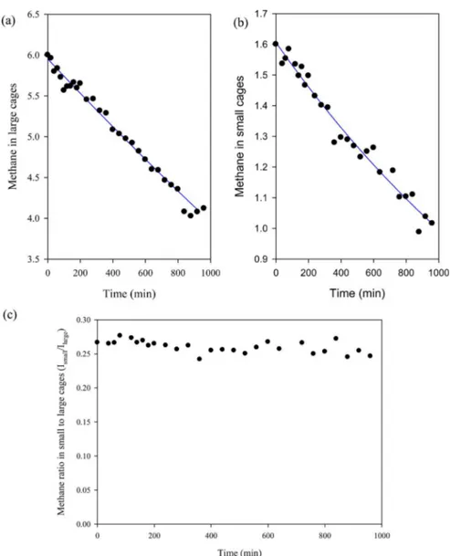
Figure 3(a),(b) shows the amount of methane in large and small cages, respectively, which was obtained from the integrated intensities in Figure 2 and the unit cell composition
of structure I methane hydrate. The methane hydrate composition can be written in terms of the unit cell contents: (2S)·(6L)·46H2O, where L is the large cage occupancy, and S is
the small cage occupancy. Our previous works indicated the small cages occupancy was 0.8 and the value for large cages was close to 1.0, usual values needed to stabilize the cage structure.13Accordingly, we estimated the amount of methane in large and small cages considering the unit cell formula of structure I, (1.6S)·(6.0L)·46H2O, and cage occupancies of
methane in both cages. Figure 3(a) suggests the methane in large cages decreases from 6.0 to 4.1 while the methane in small cages decreases from 1.6 to 1.0, as seen in Figure 3(b). The final methane composition of hydrate unit cell would be (1.0S)· (4.1L)·46H2O. The ratio of methane in small to large cages
(Ismall/Ilarge) is calculated from Figure 3(a),(b) and is shown in
Figure 3(c). It is worth noting that the initial ratio was 0.27 when commencing the replacement process, and shows only slight change to 0.25, suggesting the methane composition in hydrate follows the average unit cell composition of structure I methane hydrate. This is interesting result considering that the small cages are well isolated from each other, with the large cages forming stacks in three dimensions, thus the direct exchange between gaseous CO2 or N2and CH4 in the small
cage is impossible, and the exchange process in small cages needs to involve the large cages.
For a simplified model of the replacement reaction in the hydrate phase, the overall kinetics of replacement should be dependent upon at least two parameters: the rate of the replacement reaction at the hydrate gas interface and the transport of the CO2/N2gas through the mixed hydrate layer
already formed at the gas−hydrate interface.1H and13C NMR
spectra in Figures 1 and 2 suggest that the spontaneous replacement reaction seems to occur on the surface of methane hydrates once the methane hydrates are exposed to the CO2/
N2gas mixture. Methane hydrate at the surface of the hydrate
becomes unstable when methane gas is replaced by the CO2/
N2 gas mixture, thus decomposing the surface hydrate layer.
From the 1H NMR spectra, there was no indication of
increased amounts of free water, thus it is expected that the decomposed surface hydrate layer transforms rapidly into a mixed hydrate. The thickness of the mixed hydrate layer will increase as the time progresses; therefore, the diffusion of CO2
and N2molecules through the mixed hydrate phase as well as
the diffusion of methane out of the hydrate through the mixed layer is likely to be the rate determining stage for replacement reaction in the bulk hydrate. In1H NMR spectra, from 0 to 17
h the replacement rate constant k1is evaluated as 0.002 min−1,
while the constant k1from 17 to 65 h is calculated as 0.00015
min−1. Therefore, the total replacement rate constant of k1 =
0.0007 min−1is dominantly affected by this later replacement
stage between 17 and 65 h, implying that the diffusion of CO2/
N2 gas mixture after 17 h into interaction has significantly
slowed. This reaction kinetics showed quite a similar trend of the formation of hydrate-shells on the surface of water droplets also showing a two-step process, (1) surface reaction, and (2) bulk reaction processes.28,29 In addition, the formation of a mixed hydrate layer on the methane hydrate would reduce the chemical potential difference between gas and hydrate phases, which reduces the driving force for the transport of the CO2/
N2 gas through the mixed hydrate layer. As the replacement
front moves forward into the methane hydrate, these two processestransportation of CO2/N2gas into a mixed hydrate
layer and diffusion of CO2/N2molecules thorough the mixed Figure 2.(a)13C NMR spectra as a function of time (inset: stacked
NMR spectra). (b) Time-dependence integrated intensity change of
13C NMR spectra when CH
4hydrate in silica gel is exposed to 20 mol
% of CO2and balance N2gas mixture at 273 K and 100 bar.
Environmental Science & Technology Article
DOI: 10.1021/es504888n Environ. Sci. Technol. 2015, 49, 1964−1971
hydrate layer will become an obstacle for continuation of the replacement reaction.
Stationary 13C NMR spectrum of the CO
2molecules in the
hydrate cages (SI Figure S3) reveals an axially anisotropic powder pattern reflecting the anisotropic motion of CO2
trapped in the large cages of structure I hydrate after 17 h of the replacement. However, it is not possible to confirm unambiguously that CO2 molecules are also present in the
small cages of structure I hydrate, because the chemical shift of CO2in the gas phase and the small cages of hydrate is almost
identical, and the signal from the CO2molecules in the small
cages is expected to show no anisotropy. While we confirm the displacement of the methane with the CO2 molecules in the
large cages of structure I hydrate, the13C NMR spectra cannot
provide the exact composition of the hydrate. Therefore, the direct measurement of the composition of gas released from the hydrate phase was carried out. The effect of pore size in silica gel was also investigated using silica gel materials with different pore sizes.
Composition Analysis of Gas and Hydrate Phases. Even though pure N2 usually forms structure II hydrate, the
CO2/N2 gas mixture forms a structure I hydrate.1 The
molecular sizes of N2 and CO2 are significantly different, so
the role of the CO2/N2gas molecules during the replacement
reaction will be different. The inclusion of CO2in hydrate cages
after the replacement reaction was confirmed by our13C NMR
results (SI Figure S3), but our NMR results could not reveal the occupancy of N2in hydrate cages. In addition, through the
microscopic approach, we obtained 42% of CH4 recovery by
using a N2 and CO2 gas mixture. Therefore, the question
remains as to which of the two molecules replaces CH4in the
hydrate cages.
In order to investigate the composition of hydrates after the replacement process, a macroscopic approach was used to measure the vapor and hydrate phase compositions. We prepared pore water-containing silica gels having different pore sizes (average pore sizes of 6, 15, and 30 nm) through solid−vapor equilibrium processes in desiccators. Prepared in this fashion, water-containing silica gels were placed in a high pressure cell, and pressurized with CH4up to 140 bar. After
confirming hydrate formation in silica gel pores, CH4hydrates
in the different pore-sized silica gels were contacted with a CO2/N2 gas mixture at 100 bar for 60 h. After that, the
compositions of both vapor and hydrate phases were measured.
Figure 3.Time dependence of methane in hydrate unit cell, (a) methane in large cages from13C NMR spectra, (b) methane in small cages, and (c)
the ratio of methane in small to large cages from13C NMR spectra during the replacement process in silica gel pores of nominal size 15 nm at 273 K
The composition of the hydrate phase was obtained by measuring the composition of gas dissociated from the hydrate phase. The vapor and hydrate phase composition after the replacement reaction of CH4hydrate with the gas mixture (20
mol % for CO2and 80 mol % for N2) are shown in Figure 4.
Figure 4 shows the composition of the vapor phase contacting the hydrate phase after the replacement reaction for CH4hydrate in silica gel having an average 15 nm pore size.
The initial composition is 20 mol % of CO2and 80 mol % of
N2, but after 60 h of replacement reaction, the CO2 and N2
decreased to 10 and 69 mol %, respectively. It is noted that the CH4was detected as 21 mol %, which is assumed to have been
released entirely from the hydrate phase due to the replacement. The initial mole ratio of N2 to CO2 was about
4, but this decreased to about 7. This gives us important
information about the replacement reaction, implying that there is preferential occupancy of CO2in the hydrate cavities. CO2
can easily replace CH4 in large cavities of sI hydrate due to
favorable thermodynamic conditions of CO2hydrate and the
molecular size of CO2, and the number ratio of large to small
cavities in the sI hydrate is three, and thus; preferential occupancy of CO2is reasonable.22As the average pore size in
silica gel changes, there is no significant change of the vapor phase composition. For the silica gel with the average pore size of 6 nm, the vapor phase concentrations of the CO2and N2
after the replacement is complete are 9 and 68 mol %, and for the silica gel with the average pore size of 30 nm are 10 and 63 mol %, as shown in Figure 4 and SI Table S1. All vapor phases after the replacement reaction show similar CH4contents from Figure 4.Vapor and hydrate phase composition after 3600 min of replacement reaction with 20 mol % CO2and balanced N2gas mixture in different
pore sizes of silica gel.
Figure 5.Vapor and hydrate phase composition after 3600 min of replacement reaction with 40 mol % CO2and balanced N2gas mixture in different
pore sizes of silica gel.
Environmental Science & Technology Article
DOI: 10.1021/es504888n Environ. Sci. Technol. 2015, 49, 1964−1971
21 to 27 mol % and N2/CO2 ratios of ∼7 regardless of the
average pore size.
Figure 4 also shows the composition of the hydrate in silica gel with the average pore size of 15 nm, as the CH4is 53 mol %
and the N2 and CO2 are 23, 24 mol %, respectively. This
implies that both N2 and CO2 molecules participate in the
replacement reaction, implying that when the N2and CO2gas
mixture contact the CH4hydrate, both gas molecules replace
CH4in hydrate cages. Notably, the amounts of CH4retained in
the hydrate phases after the replacement reaction has decreased along with the increase in the average pore size from 15 nm (53 mol % CH4) to 30 nm (37 mol % CH4), while there was no
detectable increase for the silica gels with the average pore sizes of 6 nm (55 mol %) and 15 nm (53 mol %). Considering the similar vapor compositions of three different pore size experiments, these results imply that the difference in the chemical potential between the vapor phase and hydrate surface is a more important factor for the driving force of the replacement reaction than any pore size effect. The in situ1H
NMR spectroscopic results above showed that 81% of free water was converted to a hydrate phase on 40−75 μm sized silica particles with 15 nm pore size. The values of hydrate conversion and the thickness of the formed hydrate solid might be different when the particle and pore sizes vary and thus, the retained CH4compositions might also be different from each
other when the chemical potential difference between vapor and hydrate surface is reduced enough to approach the steady state. Additional experiments with different injection compo-sitions of N2and CO2support this explanation (see below) but
further study is needed for a more concrete conclusion. Figure 5 and SI Table S2 show the vapor and hydrate phase composition when CH4hydrate is contacted with a 40 mol %
CO2and N2gas mixture for 60 h at 274 K and 100 bar. The
increased concentration of CO2 in the injected gas mixture
slightly elevates the amount of the released methane (25−28 mol %), but it is not very significant. However, the ratio of CO2
to N2in the hydrate phase increased to ∼3 from ∼1 for the 20
mol % CO2and N2mixture injection. All three experiments in
Figure 5 and SI Table S2 show similar vapor compositions (∼2.7 N2/CO2ratio and ∼27 mol % CH4) to each other. The
amounts of retained CH4 in the hydrate phases show similar
trends to the ones for the 20 mol % CO2 and N2mixture in
Figure 4 and SI Table S1. These results suggest that the variation in injection gas composition rarely affects the replacement ratio, as this was between 44 and 62% for injection gases of two different CO2compositions. As already
discussed above, the difference in the chemical potential in the vapor and hydrate phases is the driving force for the replacement reaction, and for the closed system studied it will decrease continuously because of the release of the methane from the hydrate phase into CO2 and N2gas phase.
We also note that the partial hydrate composition of the hydrate phase near the surface as well as the inner pore space may be different as the replacement reaction proceeds. Therefore, the replacement reaction slowly reaches a steady state as CH4 is replaced near the surface. Eventually, the
chemical potential of the vapor and hydrate phases will be in a pseudosteady state. Schicks et al. reported that that all of the CH4can be replaced by flowing pure CO2over CH4hydrate,
but that the reaction is reversible, implying that the CO2
hydrate can be converted to CH4hydrate with a steady stream
of CH4. Therefore, in order to maintain the driving force, the
vapor phase composition needs to be replenished with fresh
CO2/N2 mixture while recovering methane from the vapor
phase. More studies are required for a better understanding of the driving force for replacement reaction and to find ways to maintain it over the course of replacement process.
As a preliminary approach to the application of the replacement technique, we have monitored the microscopic and macroscopic behavior of structure I methane hydrate in a course of CH4 replacement by N2 and CO2 mixtures. The
results suggest that the replacement reaction will be useful for enhancing the methane hydrate production already developed with the depressurization method. During the production of methane from the hydrate layer using depressurization, i.e., dissociation of the solid hydrate, the hydrate layer will experience endothermic cooling, and the production efficiency likely will decrease. At that moment, there will be free methane gas in the pore structure of the hydrate layer along with free water dissociated and ice from methane hydrate. Injection of a CO2/N2 gas mixture into this hydrate layer would produce
more methane as free methane gas in the pore structure and methane replaced with CO2/N2will be produced at the surface.
Moreover, as the replacement reaction is not accompanied by a large scale melting of the hydrate phase and free water production, the hydrate layer structures remain intact and will be stabilized by the formation of a mixed hydrate layer. An additional benefit during this process is the permanent sequestration of CO2 in the hydrate layer. Therefore,
combining depressurization with the replacement technique will provide many benefits that can be adopted in field practices to produce the methane hydrate deposits.
■
ASSOCIATED CONTENT*
S Supporting InformationFigure S1, (a) NMR spectrometer coupled with gas handling system and (b) high pressure cell for spectroscopic experi-ments. Figure S2, (a)1H NMR spectra in 15 nm silica gel at
276 K and 140 bar and (b) the integrated intensity of the resonance of free water as a function of time. Figure S3, Full range spectra of 13C NMR spectra after the replacement reaction is finished with 20 mol% of CO2and balance N2gas
mixture at 273 K and 100 bar. Table S1, Composition of vapor and hydrate phases when CH4hydrate in silica gel is exposed to
20 mol% of CO2and balanced N2gas mixture at 273 K and 100
bar. Table S2, Composition of vapor and hydrate phases when CH4hydrate in silica gel is exposed to 40 mol% of CO2and
balanced N2gas mixture at 273 K and 100 bar. This material is
available free of charge via the Internet at http://pubs.acs.org.
■
AUTHOR INFORMATIONCorresponding Author
*Tel: +82-42-350-1521; fax: +82-42-350-1510, e-mail: Yutaek. seo@kaist.ac.kr.
Present Address #
Max Planck Institute for Solid State Research, Heisenbergstr. 1, 70569 Stuttgart, Germany
Notes
The authors declare no competing financial interest.
■
ACKNOWLEDGMENTSThis work was supported by the Global Leading Technology Program of the Office of Strategic R&D Planning (OSP) funded by the Ministry of Knowledge Economy, Republic of Korea (10042424), and also by the Industrial Infrastructure
Program (Infrastructure for Offshore Plant Resources R&D Center) through the Korea Institute for Advancement of Technology (KIAT) grant funded by the Korea Government Ministry of Trade Industry & Energy (N009700001).
■
REFERENCES(1) Natural Gases, 3rded.; CRC Press: Boca Raton, FL, 2008.
(2) Kvenvolden, K. A. Natural Gas Hydrates: Introduction and History of Discovery. In Natural Gas Hydrate in Oceanic and Permafrost Environments; Max, M. D., Ed.; Kluwer Academic Publishers: Dordrecht, 2000; pp 9−16.
(3) Moridis, G. J.; Sloan, E. D. Gas production potential of disperse low-saturation hydrate accumulations in oceanic sediments. Energy Convers. Manage. 2007, 48, 1834−1849.
(4) Tang, L.-G.; Li, X.-S.; Feng, Z.-P.; Li, G.; Fan, S.-S. Control mechanisms for gas hydrate production by depressurization in different scale hydrate reservoirs. Energy Fuels 2007, 21, 227−233.
(5) Holder, G. D.; Angert, P. F.; John, V. T.; Yen, S. Thermodynamic evaluation of thermal recovery of gas from hydrates in the earth. J. Pet. Technol. 1982, 23, 5508−5516.
(6) Konno, Y.; Masuda, Y.; Hariguchi, Y.; Kurihara, M.; Ouchi, H. Key factors for depressurization-induced gas production from oceanic methane hydrates. Energy Fuels 2010, 24, 1736−744.
(7) Alp, D.; Parlaktuna, M.; Moridis, G. J. Gas production by depressurization from hypothetical class 1G and class 1W hydrate reservoirs. Energy Convers. Manage. 2007, 48, 1864−1879.
(8) Ohgaki, K.; Takano, K.; Sangawa, H.; Matsubara, T.; Nakano, S. Methane exploitation by carbon dioxide from gas hydratesPhase equilibria for CO2CH4 mixed hydrate system. J. Chem. Eng. Jpn.
1996, 29, 478−483.
(9) Hirohama, S.; Shimoyama, Y.; Wakabayashi, A.; Tatsuya, S.; Nihida, N. Conversion of CH4hydrate to CO2hydrate in liquid CO2.
J. Chem. Eng. Jpn. 1996, 29, 1014−1020.
(10) Ota, M.; Abe, Y.; Watanabe, M.; Simth, R. L.; Inomata, H. Methane recovery from methane hydrate using pressurized CO2. Fluid
Phase Equilib. 2005, 228−229, 553−559.
(11) Yuan, Q.; Sun, C.-Y.; Liu, B.; Wang, X.; Ma, Z.-W.; Ma, Q.-L.; Yang, L.-Y.; Chen, G.-J.; Li, Q.-P.; Li, S.; Zhang, K. Methane recovery from natural gas hydate in porous sediment using pressurized liquid CO2. Energy Convers. Manage. 2013, 67, 257−264.
(12) Ersland, G.; Husebo, J.; Graue, A.; Baldwin, B. A.; Howard, J.; Stevens, J. Measruing gas hydrate formation and exchange with CO2in
Benthein sandstone using MRI tomography. Chem. Eng. J. 2010, 158, 25−31.
(13) Lee, H.; Seo, Y.; Seo, Y. −T; Moudrakovski, I. L.; Ripmeester, J. A. Recovering methane from solid methane hydrate with carbon dioxide. Angew. Chem., Int. Ed. 2003, 42, 5048−5051.
(14) Lee, S.; Park, S.; Lee, Y.; Seo, Y. Thermodynamic and13C NMR
spectroscopic verification of methane − carbon dioxide replacement in natural gas hydrates. Chem. Eng. J. 2013, 225, 636−640.
(15) Schicks, J. M.; Luzi, M.; Beekow-Strauch, B. The comversion process of hydrocarbon hydrates into CO2 hydrates and vice versa:
Thermodynamic considerations. J. Phys. Chem. A 2011, 115, 13324− 13331.
(16) Lee, S.; Lee, Y.; Lee, J.; Lee, H.; Seo, Y. Experimental verification of methane-carbon dioxide replacement in natural gas hydrates using a differential scanning calorimeter. Environ. Sci. Technol. 2013, 47, 13184−13190.
(17) Tung, Y.-T.; Chen, L.-J.; Chen, Y.-P.; Lin, S.-T. In situ methane recovery and carbon dioxide sequestration in methane hydrates: A molecular dynamics simulation study. J. Phys. Chem. B 2011, 115, 15295−15302.
(18) Bai, D.; Zhang, X.; Chen, G.; Wang, W. Replacement mechanism of methane hydrate with carbon dioxide from microsecond molecular dynamics simulations. Energy Environ. Sci. 2012, 5, 7033− 7041.
(19) Park, Y.; Kim, D.-Y.; Lee, J. −W; Huh, D.-G.; Park, K.-P.; Lee, J.; Lee, H. Sequestering carbn dioxide into complex structures of naturally
occuring gas hydrates. Proc. Natl. Acad. Sci. U. S. A. 2006, 103, 12690− 12694.
(20) Koh, D.-Y.; Kang, H.; Kim, D.-O.; Park, J.; Cha, M.; Lee, H. Recovery of methane from gas hydrates intercalated within natural sediments using CO2and a CO2/N2gas mixture. ChemSusChem 2012,
5, 1443−1448.
(21) Shin, K.; Park, Y.; Cha, M.; Huh, D.-G.; Lee, J.; Kim, S.-J.; Lee, H. Swapping phenomena occurring in deep-sea gas hydrates. Energy Fuels 2008, 22, 3160−3163.
(22) Dornan, P.; Alavi, S.; Woo, T. K. Free energies of carbon dioxide sequestration and methane recovery in clathrate hydrates. J. Chem. Phys. 2007, 127, 124510.
(23) Schodenbek, D.; Martin, K. L.; Howard, J.; Silpngarmlert, S.; Hester, K. North Slope hydrate fieldtrial: CO2/CH4exchange. Offshore
Technology Conference; Houston, Texas, U.S.A., December 3−5, 2012. (24) Moudrakovski, I. L.; Ripmeester, J. A. Gas Hydrates Studied by MRI in eMagRes; John Wiley & Sons, Ltd: New York, 2007.
(25) Seo, Y.-Y.; Moudrakovske, I. L.; Ripmeester, J. A.; Lee, J.-W.; Lee, H. Efficient recovery of CO2from flue gas by clathrate hydrate
formation in porous silica gels. Environ. Sci. Technol. 2005, 39, 2315− 2319.
(26) Choi, S.; Shin, K.; Lee, H. Structure transition and tuning pattern in the double (tetramethylammonium hydroxide + gaseous geusts) clathrate hydrates. J. Phys. Chem. B 2007, 111, 10224−10230. (27) Bronnimann, C. E.; Zeigler, R. C.; Maciel, G. E. Proton NMR study of dehydration of silica gel structure. J. Am. Chem. Soc. 1988, 110, 2023−2026.
(28) Falenty, A.; Salamatin, A. N.; Kuhs, W. F. Kinetics of CO2
hydrate formation from ice powders: data summary and moleding extended to low temperature. J. Phys. Chem. C 2013, 117, 8443−8457. (29) Moudrakovski, I. L.; Sanchez, A. A.; Ratcliffe, C. I.; Ripmeester, J. A. Nucleation and growth of hydrates on ice surfaces: New insights from 129Xe NMR experiments with hyperpolarized xenon. J. Phys.
Chem. C 2001, 105, 12338−12347.
Environmental Science & Technology Article
DOI: 10.1021/es504888n Environ. Sci. Technol. 2015, 49, 1964−1971