Dynamic Simulation of Nuclear Hydrogen Production
Systems
MAby
Patricio D. Ramirez Muioz
Submitted to the Department of Chemical Engineering
in partial fulfillment of the requirements for the degree of
Doctor of Philosophy in Chemical Engineering
at the
MASSACHUSETTS INSTITUTE OF TECHNOLOGY
SSACHUSETS INSTITUTE OF TECHNOLOCY
FEB 0
9 2011
LIBRARIES
ARCHIVES
September 2010
©
Massachusetts Institute of Technology 2010. All rights reserved.
A u th or
...
<
...
. . . . .
Department o Cheical Engineering
Aug 10, 2010
C ertified by ...
...
Paul I. Barton
Lammot du Pont Professor of Chemical Engineering
Thesis Supervisor
A ccep ted by ...
William M. Deen
Professor of Chemical Engineering
Chairman, Committee on Graduate Theses
Dynamic Simulation of Nuclear Hydrogen Production
Systems
by
Patricio D. Ramirez Muioz
Submitted to the Department of Chemical Engineering on October 15, 2010, in partial fulfillment of the
requirements for the degree of
Doctor of Philosophy in Chemical Engineering
Abstract
Nuclear hydrogen production processes have been proposed as a solution to rising
CO2 emissions and low fuel yields in the production of liquid transportation fuels. In
these processes, the heat of a nuclear reactor is used to run the chemical reactions in a hydrogen plant. The resulting system is tightly interconnected and operates at very high temperature and pressure, which can lead to operational disruptions and accidents. For this reason, computational studies validating the safe operation of the system are required by regulatory authorities. In the past, safety studies have been conducted by using legacy codes, such as RELAP and MELCOR, and their focus has been the operation of nuclear power plants.
However, traditional legacy codes are not appropriate to simulate nuclear hydrogen production. The simulation of a nuclear reactor itself is already complex because it involves simulating reactor kinetics and transport phenomena. To that complexity, nuclear hydrogen production adds the need to simulate chemical reactions in the hydrogen plant. These chemical reactions cannot be represented easily in legacy codes because these codes lack the flexibility, speed and accuracy required to simulate them. Therefore, only a limited number of studies on the safety of these systems exist.
Instead of using legacy codes, this thesis proposes using equation-based simulators developed by the chemical engineering community to model and study the safety of a nuclear hydrogen production plant. Equation-based simulators were designed to be flexible, extensible and fast because they have to simulate a vast range of processes from the chemical industry. Thus, they provide a good platform for the simulation of nuclear hydrogen production systems. This thesis explains the models used for the different parts in the nuclear hydrogen production plant, and then presents the response of this plant model to different accident scenarios.
The first contribution of this thesis is a novel equation-based model for the heat transfer loop connecting a nuclear reactor and a hydrogen production plant. This heat transfer loop uses helium as the heat transfer fluid, which makes simulating its behavior difficult because of the need to model gas dynamics. To resolve this, three models for gas dynamics and two set of coupling conditions for boundary variables
were tested in JACOBIAN, an equation-based simulator. The three models for gas dynamics in combination with a novel approach to set coupling conditions for bound-ary variables were able to represent the interesting time scales accurately in transient scenarios. The accuracy and computational speed of these simulations outperformed those produced by a reference model created in RELAP, a legacy code.
The second contribution is a model of a nuclear hydrogen production plant using high-temperature steam electrolysis to produce hydrogen. This model was created to study the effect of potential accidents on the nuclear reactor. It included detailed models of the nuclear reactor and heat transfer loop, and a partial model of the electrolysis plant. The nuclear reactor was modeled as a pebble bed modular reactor, which is one of the safest designs available. The reactor was connected to the hydrogen production plant using the heat transfer loop model already developed in this thesis. The hydrogen production plant was partially represented as a steam superheater in the heat transfer loop.
The third contribution is the demonstration of the safety characteristics of the nuclear hydrogen production plant by subjecting the plant model to three accident scenarios. The scenarios involved disruptions in the hydrogen plant or in the heat transfer loop, and all of them-directly or indirectly-lead to a loss of heat sink capacity for the nuclear reactor. This resulted in an increase of the nuclear reactor core temperature, which was quickly moderated by the fission power reduction at the fuel pebbles and by the safe design of the nuclear reactor. As a consequence, the maximum temperature reached in the core was always less than the fuel melting point and the reactor was always in a safe condition. The heat transfer loop could suffer the rupture of a pipe in one of the scenarios, and design modifications to address this were suggested.
This thesis' results partially prove that nuclear hydrogen production plants could be safe, and simultaneously, that equation-based simulators are good platforms to demonstrate the safety of these plants. Developing these models and tests further will help guarantee the safety of the plant and obtain regulatory and public approval for this new nuclear application.
Thesis Supervisor: Paul I. Barton
Acknowledgments
Thank you, Corrinne Fogg, for your love and support during the PhD; the journey was rough, but you always had a smile in your face. I could not have made it without such a wonderful wife.
Professor Paul Barton, I appreciated and enjoyed having you as my advisor. You not only taught me about dynamic systems, but also attention to detail and the highest professional standards. I know I was not the easiest student, so thank you for your patience and financial support all these years.
Professor Kazimi and Professor Green, thank you for being part of my thesis committee and for your time reviewing my work. Your help was fundmental to learn about nuclear systems and how to be a better scientific communicator. My gratitude also goes to Professor Jensen and the Chemical Engineering Department at MIT for educating me and for providing financial support at different times during my studies. Finally, my work would not have been possible without the help of gifted researchers: Dr. Memmott (MIT), Dr. Hejzlar (MIT), Dr. Sherman (SNRL), Dr. Herring (INL) and Dr. Davis (INL), Dr. Vilim (ANL).
Many thanks to my labmates in the Barton group for their friendship and academic advice; working with you helped me grow a great deal. Dr. Ajay Selot, your technical guidance and lessons made me a better researcher; listening to your point of view in different topics from economics to human nature made a better person-thank you. Professor Alexander Mitsos, thank you for your constant encouragement and strategies to do good research; you believed in me more than I did. Dr. Cha Kun Lee, I appreciated your friendship and your teaching me DSL despite the fact that you were extremely busy finishing your thesis. Dr. Derya Ozyurt, thank you for starting the project that was the foundation of my thesis and for sharing with me your knowledge about nuclear hydrogen production systems. Professor George Bollas, I am grateful to you for being my project colleague and for shouldering the project responsibilities with me. Geoff Oxberry, thank you for your discussions about how to best present my work to professors and for making the lab environment welcoming.
Matt Stuber, I am indebted to you for your fashion advice and car advice-everything was spot on. I enjoyed working with all the exceptional researchers in the lab: Achim Wechsung, Spencer Schaber, Yang Chen, Professor Thomas Adams II, Mehmet Yunt, Yang Chen, Xiang Li, Richard Lakerveld, Kamil Khan, Ruth Misener, Vibhu Prakash Saxena, Earl Solis, John Tolsma, Brian Simpson, Joe Scott, Audun Aspelund, Lars Hellemo, and Emre Armagan.
Thank you to all my friends in Boston and in Chile for the great times together and the encouragement all these years. In particular, I would like to extend my sincere gratitude to Joel Yuen, for the great discussions and the fine cooking; you are a truly reanaissance man and my hero. Arman Haidari, I enjoyed our conversations about running and school. Biz Bose, thank you for the motivation and help to get the job I wanted. Surasak Chunsrivirot, our table tennis matches were delightful. Ian Hoag, doing adventure racing with an ex-Navy SEAL is one of the best training experiences I could have ever had. Professor Luis Rademacher, your example motivated me to come to MIT and your support helped me get there. Cristian Bawlitza, you have a been wonderful friend all these years-thank you.
Thank you to all the staff members of the Chemical Engineering and Nuclear Engineering departments; you not only made my life infinitely easier, but also you cheered me on every single time. In particular, I would like to thank Suzanne Maguire, Katie Lewis, Christine Preston, Barbara Balkwill, Rebecca Hailu, Craig Abernethy, Carolyn Carrington, Melanie Miller, Alina Haverty, Jean Belbin, and Fran Miles.
I'm indebted to Kathy Neumueller, Julie Cook, Hernan Saenz, and to the people at Bain & Co. in Dallas. You let me spend a summer at your great office and gave me the opportunity to come back as a full-time employee after finishing my PhD. This gave me extra motivation to finish my studies.
Finally, thank you Dario Ramirez and Alejandra Mufioz, I could not be here with-out you. My achievements are only the result of being raised by a great family. Thank you, Paula Ramirez, for being there all these years to share your PhD experience with your brother. Blanca and Ana, I'm sorry I didn't spend as much time as I wanted with you; I will make up for that in the coming years.
Contents
1 Introduction 15
2 Background 19
2.1 Nuclear energy to aid fuel production . . . . 19
2.1.1 Current transportation energy challenges . . . . 20
2.1.2 New nuclear applications for hydrogen and heat . . . . 23
2.1.3 Nuclear hydrogen production can make the biggest impact . . 28
2.2 The need for new computational models . . . . 30
2.2.1 Legacy codes lack simulation features . . . . 31
2.2.2 Equation-based simulators are a good alternative . . . . 32
2.3 Nuclear hydrogen plant used in this thesis . . . . 36
2.3.1 PBMR and PCU Operation . . . . 37
2.3.2 H TSE . . . . 39
2.3.3 Heat transfer loop . . . . 40
3 Dynamic simulation of a heat transfer loop for alternative nuclear reactor applications 43 3.1 Introduction . . . . 43
3.2 Using equation-based languages for the simulation of novel nuclear ap-plications . . . . 46
3.2.1 Equation-based simulators provide flexibility, speed and accuracy 46 3.2.2 Simulation challenges in equation-based simulators are minimal and mostly related to initial conditions . . . . 48
3.3 Modeling the heat transfer loop . . . .
3.3.1 Dynamic models in JACOBIAN . . . .
3.3.2 RELAP model for comparison . . . .
3.4 Model Performance Evaluation . . . .
3.4.1 Test 1: Feasibility and steady-state profiles .
3.4.2 Test 2: Dynamic simulation profiles . . . . .
3.4.3 Test 3: Computational time . . . .
3.5 Conclusions .. . . . .
4 Transient analysis of a nuclear hydrogen production facility
4.1 Introduction . . . .
4.2 Definition of the system . . . . 4.3 Dynamic model of a nuclear hydrogen production system . . .
4.3.1 Equation-based simulators as a simulation platform . .
4.3.2 Nuclear reactor model . . . .
4.3.3 Heat Transfer Loop Model . . . .
4.4 Transient simulations . . . .
4.4.1 Loss of heat sink accident . . . .
4.4.2 Loss of flow in the heat transfer loop . . . .
4.4.3 Leak in the heat transfer loop . . . .
4.5 Conclusion . . . . 5 Conclusions
A Discretization of Gas Dynamic Equations
A.1 Discretization of the continuity equation . . . . A.2 Discretization of the momentum equation . . . . A.3 Discretization of the energy equation . . . . B JACOBIAN code . . . . 50 . . . . 51 . . . . 61 . . . . 62 . . . . 62 . . . . 64 . . . . 71 . . . . 71 75 . . . . 75 . . . . 77 . . . . 80 . . . . 81 . . . . 82 . . . . 87 . . . . 88 89 . . . . 93 . . . . 95 . . . . 98 101 105 107 109 115 119
List of Figures
2-1 Using alternative feedstocks to produce liquid fuels increases C0 2-eq
em issions [28]. . . . . 21
2-2 Equation-based simulation languages allow the variables and equations describing physical and chemical phenomena to be declared explicitly
[5]. . . . . 34
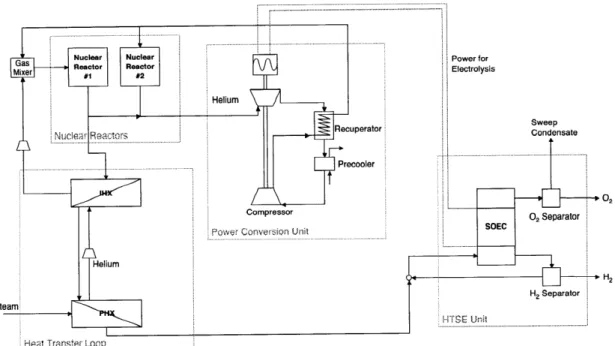
2-3 The nuclear hydrogen production used in this thesis is a combination
of technologies in development. . . . . 37
2-4 The design of fuel pebbles for PBRs avoids meltdowns by having a high fusion point (2000 C) and decreases the possibility of radiation spread
[26]. . . . . 39
2-5 The SOEC cell dissoaciates superheated steam into hydrogen and
oxy-gen [36). . . . . 41
2-6 A HTSE plant is designed to be built in modular form [42]. . . . . 41
2-7 Heat transfer loop [8]. . . . . 42
3-1 Nuclear hydrogen production is an example of novel nuclear
applica-tions. The design of the heat transfer loop requires special attention. 45
3-2 Discretizing the gas dynamics equations using combination of standard grid and a staggered grid makes the solution of the system more stable. 54 3-3 One approach to set the boundary variables; it uses Prn as suggested
in the literature [27]. . . . . 57
3-4 Alternative approach to set the boundary conditions for a gas dynamics
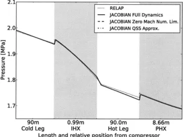
3-5 RELAP model used to benchmark JACOBIAN models. . . . . 62 3-6 Heat transfer loop's pressure profiles at steady state in JACOBIAN
match RELAP's profiles with small differences. . . . . 64
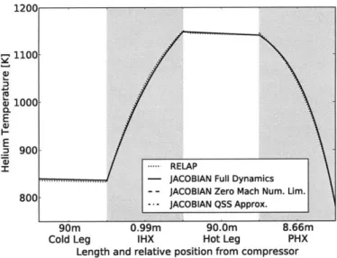
3-7 Heat transfer loop's temperature profiles at steady state in JACOBIAN
match RELAP's profiles with small differences. . . . . 65
3-8 The heat transfer loop's total helium mass decreases in RELAP after
introducing 50% decrease in PHX's cold stream inlet flowrate. .... 66
3-9 Pressure of helium in the loop at the end of the PHX after a 50% decrease in PHX's cold stream flowrate. RELAP simulation reaches a lower pressure than that in JACOBIAN simulations because of RE-LAP's numerical error in mass conservation; however, RELAP and
JACOBIAN models respond with the same speed to the step change. 67
3-10 Temperature of helium in the loop at the end of the PHX after a 50% decrease in PHX's cold stream flowrate. RELAP simulation reaches a lower temperature than that in JACOBIAN simulations because of RELAP's numerical error in mass conservation; however, RELAP and
JACOBIAN models respond with the same speed to the step change. 68
3-11 Pressure of helium in loop at the outlet of the compressor; the time scale of the response to a change in the compressor is similar again in the four models, but it differs during the first second of the transient. RELAP's numerical errors in mass conservation affect the final steady
state. . . . . 69
3-12 Temperature of helium in loop at the outlet of the compressor; the response to a change in the compressor is similar again in the four models, but it differs during the first second of the transient. RELAP's numerical errors in mass conservation again affect the final steady state. 69 3-13 The RELAP model's pressure profile presents oscillations during the
first 0.5 s of the transient because of pressure wave effects in the helium. The simplifications used in the JACOBIAN models distort or eliminate
3-14 The RELAP model's temperature profile presents oscillations during the first 0.5 s of the transient because of pressure wave effects in the helium. The simplifications used in the JACOBIAN models distort or
eliminate these oscillations . . . . 70
3-15 Heat transfer loop simulations in JACOBIAN are more than 10 times
faster than corresponding simulations in RELAP. . . . . 72
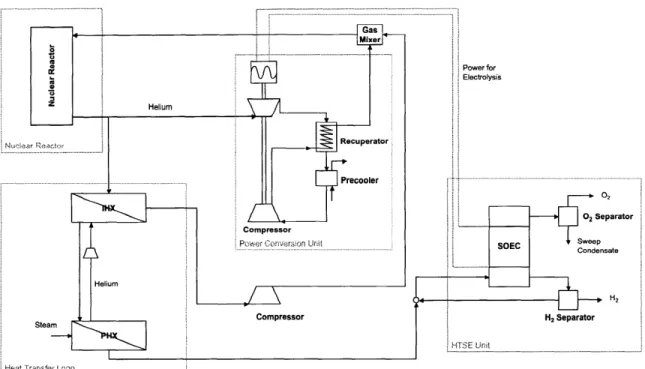
4-1 Nuclear hydrogen production system studied; the units surrounded by
the dashed line will be simulated in this study. . . . . 78
4-2 The. PBMR is safe, modular, and economical, and it can produce the
high-temperature heat needed to run hydrogen production plants. . . 79
4-3 After a loss of heat sink accident, the temperature in the cold leg of
the heat transfer loop increases more than 3300C. . . . . 90
4-4 Increased temperature in cold pipe after loss of heat sink accident
decreases pipe's stress resistance from over 105 hrs to less than 1 hr. . 91
4-5 After a loss of heat sink accident, the helium entering the core is hotter,
but its temperature is lower at the outlet. . . . . 92
4-6 After a loss of heat sink accident, the average temperature in the fuel
slightly increases, which leads to a reduction in the reactor power. . . 92
4-7 After a loss of flow in the heat transfer loop, the helium temperature
around the loop stays within specifications. . . . . 94
4-8 After a loss of flow in the heat transfer loop, the temperature of helium at the core inlet increases. The core response reduces the temperature
at the core outlet. . . . . 94
4-9 After a loss of flow in the heat transfer loop, the core reacts safely by
reducing the fission power. . . . . 95
4-10 After a leak accident in the heat transfer loop, the temperature of
4-11 After a leak accident in the heat transfer loop, the temperature at the core inlet slightly increases, which results in a minor temperature
decrease at the core outlet. . . . . 97
4-12 After a leak accident in the heat transfer loop, the heat transfer loop still can remove a significant amount of heat from the nuclear reactor coolant. This results in a power reduction of 24 MWth. . . . . 98
A-I A combination of standard grid and a staggered grid is used to dis-cretize the gas dynamics equations. . . . 106
A-2 ith control volume in the standard grid. . . . 108
A-3 ith control volume in the standard grid. . . . 109
A-4 ith control volume in the staggered grid. . . . 110
A-5 ith control volume in the staggered grid. . . . 110
A-6 ith control volume in the staggered grid with a change in section. . . . 111
A-7 ith control volume in the staggered grid. . . . 114
List of Tables
2.1 High-temperature gas reactors have been developed since the 1960s; the current ones being developed today are at the commercial scale
[10, 65]. . . . . 29
2.2 Four different nuclear hydrogen production programs are in
Chapter 1
Introduction
Replacing crude oil with more local and more affordable feedstocks, and decreasing
CO2 emissions are the most important problems that the U.S. needs to tackle
re-garding transportation fuels [12]. Oil is fundamental for transportation in the U.S.; it accounts for 95% all the energy used in this sector. Yet its sourcing is increas-ingly more complex; two thirds of oil is imported mostly from politically unstable regions, and the availability of cheap-to-process light crude oil is decreasing [13]. This has resulted in high prices [6] and an oil supply chain with a higher risk of dis-ruption. At the same time, the processing of oil into liquid fuels and the combustion
of these fuels emits large amounts of CO2; thus, increasing the CO2 concentration in
the atmosphere. This higher CO2 concentraion is believed to affect the climate and
catastrophic consequences have been projected.
To produce liquid fuels from alternative feedstocks and decrease CO2 emissions
simultaneuously, it appears beneficial to use new nuclear applications to generate heat and hydrogen to support these novel production processes. Affordable and more local feedstocks such as oil sands, coal and biomass can be good replacements for crude oil in liquid fuel production. Unfortunately, their processing into liquid fuels requires large amounts of hydrogen and heat, which are currently generated by consuming natural
gas or the same feedstock. This results in emissions of considerable amounts of CO2
in the supply chain (fuel chain), which can more than double the total emissions of the fuel chain. Also, when the feedstock itself is consumed to run operations,
low fuel yields are achieved. CO2 emissions and low yields can be avoided by using nuclear energy, which can provide the necessary hydrogen and heat. Several new nuclear applications to support liquid fuel production processes have been proposed, and special reactors are in development for these purposes.
Demonstrating the safety of these new nuclear applications with computational simulations is fundamental to obtaining regulatory approval. Producing hydrogen by using thermal power from a nuclear reactor requires a tight coupling between the reactor and the hydrogen production plant. Using heat from a nuclear reactor to support a liquid fuels production plant also requires tight coupling. These systems will operate at extreme conditions that can cause operational upsets and affect the nuclear reactor. Validating that the reactor and system will behave safely during this and other extreme upsets is required to obtain approval from authorities. This is achieved in part by studying the system with computional simulations, which allow different combinations of conditions to be tested without risking real accidents. Computational simulations have been used extensively to study nuclear reactors in power plants, and
different legacy codes exist for this (e.g., RELAP [52], MELCOR [14]).
However, legacy codes do not have enough flexibility, speed and accuracy to sim-ulate these new nuclear applications. The simulation of nuclear reactors is already complex because it involves simulating reactor kinetics and transport phenomena. To that complexity, new nuclear applications add the need to simulate chemical reac-tions in the hydrogen plant or in the liquid fuels plant. Chemical reacreac-tions cannot be represented easily in legacy codes because these codes lack the flexibility, speed and accuracy to simulate them. Some efforts have been made to modify legacy codes to represent chemical reactions, but they involve large teams of scientists. This situation has resulted in a limited number of studies on the safety of these systems.
This thesis proposes using equation-based simulators to model the new nuclear applications and illustrates this by creating and simulating models for a nuclear hy-drogen production plant. Equation-based simulators were created to simulate a large range of process in the chemical industry. Thus, they are specifically designed to be extensible, flexible and fast, and can provide the platform needed to model new
nuclear applications. From all the proposed nuclear applications, nuclear hydrogen production is the one that can have the biggest impact. Therefore, nuclear hydrogen production was used as the case study and high temperature steam electrolysis was chosen as the specific method of production.
The specific contributions of this thesis are:
" a set of models to represent a nuclear reactor coupled to a hydrogen production plant,
" a new method to set the boundary conditions in a closed heat transfer loop using gas as the heat transfer fluid, and
* the simulation of three new possible accident scenarios encountered in a hydro-gen production plant.
This thesis is structured in five chapters. Chapter 2 explains how new nuclear applications -in particular nuclear hydrogen production- can help solve problems in the production of fuels for the transportation sector. It also explains the computa-tional difficulties in simulating the new nuclear applications and how equation-based simulators can be an appropriate platform. Chapter 3 explains how to simulate cor-rectly a heat transfer loop connecting a nuclear plant and a hydrogen plant. Chapter 4 presents the dynamic models for the nuclear reactor, the heat transfer loop and part of the hydrogen plant. These models are used to represent and analyze three possible accident scenarios caused by upsets in the hydrogen production plant or the heat transfer loop. Chapter 5 presents the final conclusions and recommendations.
Chapter 2
Background
This chapter explains the problems associated with fuel production processes from alternative feedstocks in the U.S. It details how nuclear energy can help solve these problems by providing heat and hydrogen for the new facilities needed. It also de-scribes the challenges in the simulation of these new nuclear applications and how equation-based simulators can provide a good platform to replace/supplement legacy codes. It finally specifies the nuclear hydrogen plant used as a case study: a pebble-bed reactor coupled to a high-temperature electrolysis plant.
2.1
Nuclear energy to aid fuel production
One of the key priorities for the transportation sector in the U.S. is to replace/reduce crude oil in the production of liquid transportation fuels. To do this, alternative feedstocks have been proposed and studied: oil sands, coal, biomass and natural gas [28, 12]. These alternative feedstocks are advantageous because they can be produced locally or in politically stable countries, and because they are either cheaper or cleaner. However, the pathways to transform them into liquid fuels require large amounts of heat and hydrogen, which are generated by consuming natural gas or the same
feedstock. This results in the emission of large quantities of CO2 and low fuel yields.
Using nuclear energy to produce the heat and hydrogen needed can eliminate the
with alternative feedstocks. This section explains the problems in the production of liquid fuels using alternative feedstocks and details how nuclear energy can help with heat and hydrogen production. At the same time, this section explains that nuclear hydrogen production will be the focus of this thesis because this application might have the biggest impact in the future.
2.1.1
Current transportation energy challenges
Transforming alternative feedstocks (e.g., oil sands, coal, biomass and natural gas) into liquid transportation fuels requires a supply chain (fuel chain) with several steps:
extraction/production, conversion/refining and transportation/distribution [28]. Un-fortunately, these fuel chains are very energy intensive and can consume more than five times the energy needed by the fuel chain for crude oil. This also results in
corre-sponding large CO2 emissions, as the CO2 emissions are approximately proportional
to the energy used in each step. The energy demand and emissions vary depending on the process and feedstock used, but are caused mainly by the production of process heat and hydrogen.
1. Light crude oil. Production of liquid transportation fuels from light crude oil (e.g., Arab light crude) already requires large amounts of energy, which results
in fuel chain emissions of 143 g CO2 equivalent per mile driven in a SUV (g
C0 2-eq/mile in SUV) or 39% of the CO2 emitted by burning the fuel itself [28].
In particular, refineries are the largest energy consumers in the U.S. and most of this energy is used to generate heat and hydrogen. High-temperature heat (500-700'C) is required for several operations, distillation and thermal cracking being the major demands. This heat input accounts for 10% of the energy in the final fuel. The total heat input required to process the crude oil consumption in the U.S. is 142 GWth or about 50% of the nuclear capacity installed in the U.S [12]. Hydrogen is also widely used at different process steps, hydrotreating and hydrocracking being the most important ones. Refineries use approximately 4 million tonnes of hydrogen per year [64], which makes them also the largest
1200 1000 5 800-Transportation/ E 600 -Extraction/ distribution production 0 400
200-0 Arab light crude Alberta oil sands Wyoming coal Biomass
Figure 2-1: Using alternative feedstocks to produce liquid fuels increases C0 2-eq
emissions [28].
consumers of hydrogen in the U.S.
2. Heavier crudes and oil sands. As heavier forms of crude oil are used for the
production of liquid transportation fuels, the processing becomes more complex
and results in higher energy consumption and higher CO2 emissions. For
exam-ple, the fuel chain for Alberta oil sands emits 193 g C0 2-eq/mile in SUV or 52%
of the CO2 emitted when burning the fuel (Fig. 2-1) [28, 31]. These emissions
correspond to 35% more than the emissions generated in the processing of light crude.
In the case of oil sands, the higher CO2 emissions and energy requirements are
explained by the increased intensity of the mining, extraction and upgrading processes. The mining of oil sands in open pits uses large quantities of fuel to operate the equipment (e.g., shovels) and to move oil sands to extraction facilities by hydrotransport pipelines. The extraction of oil sands requires large quantities of steam to decrease their viscosity and separate the bitumen from solids. For example, in situ thermal extraction requires around 1.0 Mcf of
natural gas per barrel of bitumen [34], which corresponds to approximately 17% of the energy in the bitumen. Finally, upgrading the bitumen produces syncrude that can be processed by traditional refineries. This stage involves additional steps of distillation, cracking and hydrotreating, which need large amounts of heat and hydrogen. Most of this heat and hydrogen are currently produced from natural gas, and the requirements are about 0.1 and 0.4 Mcf of natural gas per barrel of bitumen, respectively [34].
3. Coal. Coal, a local and abundant feedstock in the U.S. (e.g., Wyoming Coal), can also be used to produce liquid transportation fuels by the Fischer-Tropsch process. However, this fuel chain requires much more energy than the fuel chain
for crude oil, and its emissions are 594 g C0 2-eq/mile in SUV or 3.2 times more
(Fig. 2-1). Most of the CO2 emissions and energy consumption are associated
with the production of hydrogen from CO and H20 in the water gas shift (WGS)
reaction: CO + H20 <-+ CO2 + H2. Additionally, this step results in very low
yields in the conversion of coal into fuel, as CO is produced by the gasification of coal. Only 30% of the carbon in the coal input to the process ends in the final liquid fuel [7].
4. Biomass. The two most important ways to produce liquid transportation fu-els from biomass are the production of ethanol by fermenting biomass-derived sugars and the production of hydrocarbon fuels by gasification and the Fischer-Tropsch process.
The production of ethanol by fermentation is an energy-intensive process. For example, producing a gallon of ethanol from corn starch requires 120% of the energy value in the ethanol gallon, and generates a corresponding amount of
C0 2-eq emissions [61]. A large part of the energy is used to produce process
heat for separation steps. Currently this heat is mostly generated by burning
natural gas, which results in large CO2 emissions. In addition, the fermentation
process itself generates C0 2, as yeast produces two molecules of ethanol and
A more efficient way to produce liquid fuels based on biomass is using gasifica-tion and the Fischer-Tropsch process to produce liquid fuels, because this pro-cess can use the biomass constituents as feedstock. This propro-cess works similarly to the one used for coal described previously. Here again, using the feedstock
to produce hydrogen in the WGS reaction accounts for a large part of the CO2
emissions, energy used and low conversion yields. The fuel chain emissions in
this case are 746 g-CO2-eq/mile SUV or 4.2 times more than the emissions for
the light crude oil fuel chain (Fig. 2-1) [28]. These extra emissions are accounted for by the energy used for cultivating, harvesting and transporting biomass. On
the other hand, such a fuel chain could be CO2 neutral if all the energy comes
from biomass or renewable sources.
Additionally in this case, it is crucial to increase the conversion yield of biomass into liquid fuels by finding alternative means of hydrogen production. Not only is it expensive and energy intensive to produce and collect biomass, but also the area that can be used to supply the biomass is limited in size. For example, one study used 17.25 miles as the average haul from the field to the plant [28]. Therefore, low conversion yields severely limit the output of a single facility. As the production of hydrogen for the Fischer-Tropsch process is the biggest factor decreasing the conversion yield, using alternative hydrogen sources can increase the output substantially.
2.1.2
New nuclear applications for hydrogen and heat
As explained above, transforming alternative feedstocks into liquid transportation fuels requires large amounts of energy to produce the hydrogen and heat needed for the processes. Producing this hydrogen and heat with conventional approaches
results in high costs, high CO2 emissions and low conversion yields, which makes it
hard to use alternative feedstocks for liquid transportation fuels. However, producing the hydrogen and heat with cheaper and cleaner substitutes could solve this problem. Nuclear energy is one of the possible substitutes and extensive applications of it to
liquid transportation fuel production have been analyzed [12]. This section reviews how nuclear energy can be used to produce hydrogen - nuclear hydrogen production - and how it can provide heat for different liquid fuel production processes.
Nuclear hydrogen production
Most hydrogen production involves significant emissions of CO2 because it relies on
fossil fuels. Coupling a very high-temperature nuclear reactor to a hydrogen produc-tion plant could provide carbon neutral and inexpensive hydrogen. Two hydrogen production technologies are being developed to do this: high-temperature steam elec-trolysis (HTSE) and the sulphur-iodine (SI) cycle [63]. These two technologies, their
applications and their benefits are explained in this section.
HTSE can produce hydrogen with no CO2 emissions and approximately double
the efficiency of traditional electrolysis. This process uses part of the heat from a high-temperature nuclear reactor to produce superheated steam with temperature in the range of 800-900 C. The rest of the high-temperature heat from the nuclear reactor is used to produce electricity using a Brayton cycle. This electricity is then used in the solid oxide electrolysis cells to produce hydrogen and oxygen from the superheated steam [63]. The use of high-temperature heat to produce electricity results in increased power cycle efficiency over previous power plants. In addition, the operation of the electrolysis cell at high temperatures enables a reduction in the electrical power needed for the electrolysis reactions. The combination of these two factors achieves thermal efficiencies in the production of hydrogen of 45% to 55% [63, 18]. This greatly exceeds efficiencies of 27% achieved by current electrolyzer technologies using electricity from earlier generations of power plants.
The SI cycle can also produce hydrogen from the heat produced by a nuclear
reactor without CO2 emissions and at high efficiency. This cycle was developed by
three chemical reactions:
I2 + SO2 + 2H20 -+ 2HI + H2SO4, (1200C)
H2SO4 - SO2 + H20 + 1/202, (830-9000C)
2H1 - I2 + H2. (300-4500C)
These reactions have been demonstrated in the laboratory and progress has been made in scale up [10]. All the reagent in these reactions is recycled, which means that only hydrogen and oxygen are the final output of the system. In this case, the high-temperature reactor is mainly used to provide high-temperature heat for the second reaction. The thermal efficiency of this process has been estimated between 45% and 55% [63].
Hydrogen produced with either of these two nuclear hydrogen production technolo-gies could be used in different liquid transportation fuel processes to reduce emissions or increase efficiency:
* Crude oil refining. In the U.S., displacing the use of natural gas for hydrogen
production in refining processes would decrease CO2 emissions by 10-15% and
would require 35-41 GWth of nuclear reactor capacity. In the U.S. in 2003, the 145 active refineries required 4.08 million tonnes of hydrogen for hydrotreat-ing, hydrocracking and other processes [64]. Almost all of this hydrogen was produced by using natural gas steam reforming, and this process accounted for
10-15% of the CO2 emissions [62, 48]. These emissions could be avoided by
us-ing hydrogen produced by nuclear hydrogen production plants usus-ing HTSE or SI. It is estimated that 60-70,000 tonnes of hydrogen per year can be produced from a 600 MWth high-temperature nuclear reactor [12]. Then, the nuclear ca-pacity required supply all the refineries in the U.S. corresponds to 35-41 GWth. This corresponds to approximately 11-13% of the current installed nuclear ca-pacity in the U.S., as the average power cycle efficiency of this caca-pacity is 32%
* Oil sands upgrading. Incorporating nuclear hydrogen production for the
upgrad-ing of Alberta oil sands could decrease CO2 emissions in the
extraction/produc-tion step by 35%. Upgrading one barrel of bitumen of Alberta oil sands requires 2.4 kg of hydrogen on average [44]. As the production of 1 kg of hydrogen from
natural gas generates 11.9 kg C0 2-eq [50], the upgrading of one barrel of
bi-tumen generates 28 kg CO2. Overall, the production of one barrel of bitumen
emits about 81 kg C0 2-eq [34], which means emissions would decrease by 35%
in this step.
Replacing all the hydrogen used for upgrading with hydrogen produced with nuclear means would require 5.1-6.0 GWth of nuclear power. In 2007, the production rate of bitumen in Alberta was approximately 700 thousand barrels per day. Thus, the corresponding requirement for hydrogen was about 0.6
million tonnes of hydrogen per day. As 60-70,000 ton-H2/yr need 600 MWth of
nuclear power for its production, satisfying this hydrogen demand would need 5.1-6.0 GWth of nuclear power.
* Converting coal to liquids or biomass to liquids. CO2 emissions in a
coal-to-liquids facility could be reduced by 49% by using nuclear hydrogen production. In a traditional coal-to-liquids facility, only 30% of the carbon in the coal is
incorporated into the final liquid fuel [7]. Most of the remaining 70% ends
as CO2 in the WGS reaction and accounts for nearly all the CO2 emissions.
Nuclear hydrogen can replace the WGS reaction to provide hydrogen for the Fischer-Tropsch process, and this would result in 66% of the carbon in coal being incorporated in the final fuel. Therefore, emissions could be reduced by 49%. A coal-to-liquids facility processing 19 thousand tons of coal per day would require 0.5 thousand tons of hydrogen per day [7]. This rate of hydrogen can be produced by a nuclear hydrogen facility with 1.7 GWth of power. Using nuclear hydrogen production to support a biomass-to-liquids facility would have a similar effect. This is crucial in the case of biomass as the production rate of the facility is limited by the area of land that can supply the facility. Thus,
doubling the carbon conversion yield would allow a single facility to double its output and achieve economies of scale.
Nuclear heat integration
Nuclear reactors can also be used to provide heat for liquid fuel production processes
and reduce CO2 emissions. This will require a customized design for heat
integra-tion, as the different steps in each process use different amounts of heat at different temperatures. Using nuclear reactors to produce heat for industrial applications -including ethanol production - has been already tried successfully in other parts of the world. This section will describe some potential uses of nuclear heat in liquid fuel production processes.
1. Refineries. The heat needed to supply refineries in the U.S. would require a nuclear capacity of 142 GWth. Most of the heat used in refineries is used in distillation and thermal cracking, and it accounts for 10% of the heat content in the final liquid fuel. The total fuel output from refineries is equivalent to 20 million barrels of oil per day; then, the nuclear capacity required in this case is 142 GWth [12]. The heat provided should be at 600-700 C, which would require designing specific equipment to transfer the heat at such high temperatures. 2. Oil sands extraction and upgrading. In the case of oil sands, heat could be
used to produce steam to extract bitumen in situ, or to separate it from solid residues [11]. In the case of extraction in situ, one pebble bed modular reactor of 250 MWth could support the production of 50 thousand barrels of bitumen per day. Other process designs are going even further by suggesting the idea of nuclear underground refining, where high-temperature heat is used to distill
the bitumen in situ [12]. A process like this would avoid all the CO2 emissions
associated with producing the high-temperature heat from natural gas and it would require a 600 MWth reactor to produce 50 thousand barrels of oil per day.
re-actors could reduce by 50% the fossil fuel use in starch-based ethanol refineries. 50% of the energy consumed in traditional ethanol refineries is used to produce steam with low temperature and pressure. The same kind of steam is produced by nuclear power plants as a by-product, and it can be easily transported for a distance of about one mile. Thus, using the steam from a nuclear power plant in an ethanol refinery is feasible, would reduce emissions and would add value to the power production in the nuclear plant. Producing 2.4 million barrels of ethanol per year would need 80 MWth of steam [12].
2.1.3
Nuclear hydrogen production can make the biggest
im-pact
As demonstrated, nuclear hydrogen production and nuclear heat coupling can both
reduce CO2 emissions and increase feedstock conversion yields. From these two new
nuclear energy applications, it is nuclear hydrogen production that can make the biggest impact in the near future. Some of the reasons for this are that nuclear
hydrogen production could reduce more than 1% of CO2 emissions in the U.S., and
that its development has made significant progress. At the same time, its application could be highly standardized, contrasting the customized integration required for heat coupling projects. Furthermore, nuclear heat coupling has not been developed much. For all these reasons, this thesis will focus on nuclear hydrogen production.
The development of nuclear hydrogen production has made significant progress. Seven high-temperature gas reactors have already been built-only two of them are operational-and five more will be built by 2020 (Table 2.1) [10]. In particular Japan and China have made considerable progress. They own the two operational reactors (the 30-MW HTTR and 10-MW HTR-10, respectively) and are developing larger versions of them (the 300-MW GTHTR300 and the 250-MW HTR-PM, respectively) [10, 65]. All these reactors are also being designed to be passively safe, which will help gain public acceptability. In addition, these reactors could be used for hydrogen production, and research efforts are also being developed in this direction (Table 2.2)
[10].
Table 2.1: High-temperature gas reactors have been developed since the 1960s; the current ones being developed today are at the commercial scale [10, 65].
Reactor Location Power He temperature Core Operation
(MWth) in/out ('C) years
Dragon UK 20 350/750 Cylindrical 1965-1975
Peach Bottom USA 115 377/750 Cylindrical 1967-1974
AVR Germany 46 270/950 Pebble bed 1968-1988
Fort St Vrain USA 842 400/775 Hexagonal 1976-1989
THTR Germany 750 270/750 Pebble bed 1985-1989
HTTR Japan 30 395/950 Hexagonal 1998-Present
HTR-10 China 10 250-300/700-950 Pebble bed 2000-Present
PBMR SA 500 350/950 Pebble bed In development
ANTARES France 600 400/850 Hexagonal In development
GT-MHR USA/Russia 550-600 490/950 Hexagonal In development
HTR-PM China 250 250/750 Pebble bed In development
GTHTR300 Japan 600 589/850 Hexagonal In development
Table 2.2: Four different nuclear hydrogen production programs are in development [10].
Company JAEA GA PBMR/Westinghouse AREVA NP
Country Japan USA SA/USA France
Reactor GTHTR300 MHR-GT PBMR ANTARES
Power 600 550-600 500 600
PCS Brayton Brayton Rankine Rankine
HPP SI HTE/SI HyS/HTE HTE/SI
Cycle Direct PCS, series in- Direct PCS, parallel Indirect, series HPP Indirect, parallel configuration direct HPP indirect HPP and PCS HPP and PCS IHX Helical coil S&T Single-stage PCHE Two stage PCHE PCS: helical coil S&T
Process: PCHE or fin plate
In addition, nuclear hydrogen production would operate as a standard standalone plant, avoiding the customized integration required by nuclear heat coupling. The hydrogen transfer is the only point of contact between a nuclear hydrogen plant supporting a fuel production plant. As hydrogen can be stored in limited quantities, the operation of the nuclear hydrogen plant is relatively independent from its fuel counterpart. Therefore, a standard modular nuclear hydrogen plant could be used to assist a large variety of fuel plants. This would make the manufacturing and deployment of nuclear hydrogen plants cheaper and faster. On the other hand, nuclear
heat coupling requires a customized integration with the fuel plant, which will make the adoption of this technology much slower.
Moreover, nuclear heat coupling has not been developed significantly. Research exploring the use of nuclear heat in refineries has not been reported yet [12]. Also, only preliminary studies have been on the use of nuclear heat to extract bitumen from oil sands [12, 11]. The development of these topics would require large multidisciplinary teams with understanding of materials, chemistry and nuclear engineering. This author does not know of such a team yet.
2.2
The need for new computational models
New nuclear applications for fuel production, such as nuclear hydrogen production, will need to demonstrate safe operation by going through a rigorous assessment, sim-ilar to the one used for nuclear power plants. This assessment involves understanding how the plant behaves during normal operation and how it responds to possible equipment failures and disruptions. In particular, the assessment will help validate the limits for the important process variables, the design of the safety procedures and the specifications for the different materials and equipment used [56]. Positive results in this assessment are fundamental to obtain a license for the reactor, because they will help guarantee the public health and safety.
The scenarios used to validate new nuclear applications will include adapted ver-sions of the ones used for nuclear power plants and new ones depending on the chem-ical processes used. Scenarios including operational disruptions will comprise the decrease/increase of heat removal by the secondary system, decrease in the reactor coolant system flowrate, reactivity and power disruptions anomalies, radioactive re-lease from a subsystem, etc. Normal operation scenarios will involve studying the procedures for the normal operational transients that the plant will experience such as start-up, shutdown and re-start.
In the case of nuclear power plants, these scenarios are studied using computer simulation codes that can model the associated physical phenomena. The leading ones
in the U.S. are MELCOR, MAAP4 and RELAP5 [57]. MELCOR and RELAP5 are used by regulatory agencies and research institutions to evaluate hypothetical severe accident events such as a station blackout or the potential for steam generator tube rupture. MAAP4 is the severe accident code most widely used by nuclear utilities and vendors because of its short run time and reduced requirements for code expertise.
However, the simulation of new nuclear applications for fuel production is more complex than the simulation of a nuclear power plant and new codes are required for this. Legacy codes lack the extensibility, flexibility and speed required to simulate chemical reactions that appear in a new nuclear application such as nuclear hydrogen production. This problem can be solved by using equation-based simulators, which are simulation platforms designed by chemical engineers to model a large variety of chemical processes. This section explains the main reasons why legacy codes, such as RELAP5, struggle to simulate nuclear hydrogen production. At the same time, this section explains how equation-based simulators can be a good platform to simulate this new kind of nuclear system.
2.2.1
Legacy codes lack simulation features
Legacy codes have been extensively used to demonstrate the safety of nuclear power plants. However, they lack the extensibility, flexibility, speed and accuracy required to represent new nuclear applications such as nuclear hydrogen production.
New nuclear applications are complex systems and their simulation requires mod-els of a variety of physical and chemical phenomena. In the case of nuclear hydrogen production using HTSE or the SI cycle, these phenomena comprise many complex chemical reactions and unit operations. HTSE involves electrolysis cells with temper-ature gradients, mass transfer and steam electrolysis reactions at the cells electrodes. The SI process involves electrolyte solutions and highly corrosive chemical reactions at high-temperature: Bunsen reaction, sulfuric acid decomposition, and HI decom-position. The dynamics all of these phenomena need to be represented in order to understand the behavior of the hydrogen production plant and how it can affect the
However, legacy codes are not designed to model these chemical and physical phe-nomena. Legacy codes have been created to model accidents in the reactor accurately
and specifically. For example, MELCOR, MAAP4 and RELAP5 can represent -with
precision - the behavior of the reactor primary loop, the fission reactions in the core,
and the core thermodynamics [57]. Yet, these codes do not have the necessary rou-tines to represent the chemical reactions and processes in new nuclear applications such as hydrogen production. Nor do they have algorithms that can efficiently sim-ulate stiff chemical reactions, which are difficult to simsim-ulate and can slow down the code's performance.
At the same time, legacy codes are hard to modify to incorporate chemical reac-tions. In these codes, the equations representing the reactor physics and the solution methods for these equations are tightly coupled. Additionally, these codes are col-lections of capabilities that have evolved and grown over the years. For example, MELCOR was initially design to be a risk assessment tool; now, it is a dynamic simulation tool [57]. This means that adding new chemical reactions and new unit operations to legacy codes requires a deep understanding of their architecture. Some research groups have attempted this, but their efforts involved years of work and large and specialized teams [43].
2.2.2
Equation-based simulators are a good alternative
Equation-based simulators used in the chemical industry are an alternative platform to legacy codes for the simulation of new nuclear applications. Chemical engineers have to deal with a large number of vastly different processes, which involve chem-ical reactions, different unit operations, complex thermodynamic models and heat and mass transfer phenomena. To design and optimize these processes, they often use equation-based simulators, which are general-purpose modeling environments for dynamic and steady-state simulation. Such simulators provide a high-level simula-tion language for the user to describe processes in terms of equasimula-tions and variables. These simulators and their supporting mathematical theory have been developed for more than 30 years and some examples of them are JACOBIAN [35], Aspen Custom
Modeler [53], and gPROMS [41]. They have been developed to be extensible, flexible, fast and accurate, and this combination of features makes them ideal to simulate new nuclear applications such as nuclear hydrogen production.
The extensibility, flexibility, speed and accuracy of equation-based simulators are achieved by decoupling the description of the physical system from the numerical methods employed to simulate this system. This is a key difference between these simulators and legacy codes, where the definition of the model is tightly coupled to its solution algorithm. On the one hand, a description of the physical system is made by declaring the model, which corresponds to representing all the unit operations individually with equations and variables. These unit operations models can be coded from scratch in the simulation language or they can be imported from a library. The ability to create new unit operation models is very important in the development of new nuclear reactor applications, as the systems have not been completely defined and are constantly changing with the results of new experimental data. On the other hand, the solution of the model is done automatically by powerful general-purpose algorithms. These algorithms assemble all the equations of the model in one single system and then solve this system directly fast and accurately by automatically identifying and exploiting problem structure such as block decomposition. Model declaration and the model solution are explained in the following.
Model declaration-flexibility
Equation-based simulation languages are declarative, which means the user only needs
to input the model as a set of differential-algebraic equations (DAEs) [5]. These
languages can represent any physical or chemical system as a combination of DAEs:
f(x(t), *(t), y(t), t) = 0
g(x(t), y(t), t) = 0
where x(t) E R'- and * E R'- represent the differential variables (those whose time
Figure 2-2: Equation-based simulation languages allow the variables and equations describing physical and chemical phenomena to be declared explicitly [5].
respectively. y E R"" correspond to the algebraic variables. f : Rl- x Rh' x Rl' x R ->
R- are the differential equations, and g : R4. x R"y x R --+ R"y are the algebraic
equations. The purpose is to specify the functional form of a model (e.g., a system of equations), and not a series of statements to be executed in a sequence (Fig. 2-2). The process model so defined is completely decoupled from the numerical methods used to solve it, which allows the user to focus solely on the model.
Furthermore, equation-based simulation languages use hierarchical decomposition, which greatly simplifies the coding of large models [5]. Hierarchical decomposition allows building models in levels-in the same way one would build a real plant. For example, a first level of simple models can represent basic units (e.g., pipes, heat exchangers, chemical reactors). A second level connects models from the first to
MODEL Vessel_With_SafetyValve PARAMETER
Vessel Volume,R AS REAL
SetPress, ReseatPress AS REAL
ValveConst AS REAL
VARIABLE
FlowIn, Flow Out,
Relief_Flow AS MolarFlowrate
Holdup AS Moles
Temp AS Temperature
Press, PressIn AS Pressure
STREAM
Inlet : FlowIn, PressIn AS MainStream
Outlet : Flow Out, Press AS MainStream
Relief : ReliefFlow, Press AS MainStream
SELECTOR
ValveFlag AS (Closed,Open)
EQUATION
# Mass balance
$Holdup = FlowIn - FlowOut - ReliefFlow
# Equation of state (perfect gas)
Press*VesselVolume = R*Holdup*Temp
# Safety relief valve with hysteresis CASE Valve Flag OF
WHEN Closed :Relief Flow = 0
SWITCH TO Open IF Press >= SetPress
WHEN Open :Relief Flow = ValveConst*Press/Temp^0.5
SWITCH TO Closed IF Press <= ReseatPress
END # CASE
represent subsystems (e.g., heat transfer loop). Finally, a third level could connect all the subsystems to assemble a plant model. With this approach, lower-level models can be easily tested and corrected, avoiding hard-to-find errors in higher-level models. In sum, equation declaration and hierarchical decomposition allow equation-based simulation languages to represent the details of new nuclear applications in a simple
and intuitive way.
Model solution-speed and accuracy
Equally important, equation-based simulators find solutions to simulations quickly and accurately. To solve simulations quickly, they assemble all the model equations into one single equation system, which is solved simultaneously by general-purpose codes for root finding and fast numerical integration. They also automatically exploit the characteristics of the equation system (e.g., sparsity, analytical derivatives, and block decomposition) to accelerate the solution process and solve 100,000s of equations in minutes. To be accurate, they use error control based on theoretical guarantees for accuracy and stability, and these estimates are controlled automatically [4]. These features are made possible by powerful algorithms: implicit predictor-corrector meth-ods for integration [3], automatic differentiation algorithms [16] and algorithms for sparse linear algebra [9]. These algorithms are explained here.
The best equation-based simulators use implicit predictor-corrector methods to integrate the system of equations numerically. They are implicit methods that use an explicit method to calculate an initial guess for the solution of the system of equa-tions at each time step. The implicit methods normally used are multi-step methods, and, in particular, variable step size, variable order Backward Differentiation Formula (BDF) methods are used [15]. These methods are very stable and can solve stiff prob-lems such as the simulation of complex systems of chemical reactions. Additionally, the step size used in the integration is controlled by the truncation error rather than the stability. Thus, the integrator can take larger time steps when the system of equations is stiff and the fast modes of the transient have decayed. This results in a faster solution of the simulation.
Automatic differentiation algorithms calculate the Jacobian (matrix of partial derivatives) of the equations analytically. These algorithms increase the speed and accuracy of the solution, because predictor-corrector methods work more efficiently with an analytical Jacobian instead of a numerical one. At the same time, these automatic algorithms avoid the tedious and prone-to-error task of deriving the an-alytical Jacobian manually. For these reasons, automatic differentiation algorithms are extensively used in equation-based languages [16, 54]
Algorithms for sparse linear algebra take advantage of the sparsity of an equation system to solve it faster. Normally, systems with more than about 20 equations will have only a few variables appearing in each equation. This creates a very sparse system, whose Jacobian will have mostly zeros. Using this information in numerical Jacobian evaluations and while solving a system's linear equations greatly increases the solution speed of the equation system.
2.3
Nuclear hydrogen plant used in this thesis
The goal of this thesis is to study the safety of a nuclear hydrogen production plant by simulating this plant's operation in an equation-based simulator. The plant selected for this is a combination of well-developed technologies: two modular pebble bed reac-tors (MPBR), a power conversion unit (PCU) using the Brayton cycle, a heat transfer loop, and a HTSE facility (Fig. 2-3). In this process, the nuclear reactor produces 500 MWth of high-temperature heat for the PCU and for the HTSE process. The PCU uses 450 MWth to produce the electricity needed in the electrolysis cell of the HTSE unit. The remaining 50 MWth of heat is transferred from the nuclear reactors to the HTSE unit by the heat transfer loop, and it is used to produce superheated steam (800-900'C). This steam is fed to the electrolysis cell where it is decomposed into oxygen and hydrogen; this reaction occurs at high temperature, which increases the efficiency of the electrolysis. The oxygen is recuperated and the hydrogen/water stream is sent to a steam separator, to be recover hydrogen.
![Figure 2-1: Using alternative feedstocks to produce liquid fuels increases C0 2 -eq emissions [28].](https://thumb-eu.123doks.com/thumbv2/123doknet/14754590.581885/21.918.163.777.123.502/figure-using-alternative-feedstocks-produce-liquid-increases-emissions.webp)
![Figure 2-2: Equation-based simulation languages allow the variables and equations describing physical and chemical phenomena to be declared explicitly [5].](https://thumb-eu.123doks.com/thumbv2/123doknet/14754590.581885/34.918.226.683.108.633/equation-simulation-languages-variables-equations-describing-phenomena-explicitly.webp)
![Figure 2-4: The design of fuel pebbles for PBRs avoids meltdowns by having a high fusion point (2000'C) and decreases the possibility of radiation spread [26].](https://thumb-eu.123doks.com/thumbv2/123doknet/14754590.581885/39.918.173.782.97.490/figure-design-pebbles-avoids-meltdowns-decreases-possibility-radiation.webp)
![Figure 2-5: The SOEC cell [36]. one cell 10 cm one 8 ft t 1.9 ft](https://thumb-eu.123doks.com/thumbv2/123doknet/14754590.581885/41.918.131.780.123.525/figure-soec-cell-cell-cm-ft-t-ft.webp)
![Figure 3-3: One approach to the literature [27].](https://thumb-eu.123doks.com/thumbv2/123doknet/14754590.581885/57.918.147.778.117.370/figure-approach-literature.webp)