HAL Id: hal-00317465
https://hal.archives-ouvertes.fr/hal-00317465
Submitted on 14 Jun 2004
HAL is a multi-disciplinary open access
archive for the deposit and dissemination of
sci-entific research documents, whether they are
pub-lished or not. The documents may come from
teaching and research institutions in France or
abroad, or from public or private research centers.
L’archive ouverte pluridisciplinaire HAL, est
destinée au dépôt et à la diffusion de documents
scientifiques de niveau recherche, publiés ou non,
émanant des établissements d’enseignement et de
recherche français ou étrangers, des laboratoires
publics ou privés.
A numerical study of two interacting coronal mass
ejections
J. M. Schmidt, P. J. Cargill
To cite this version:
J. M. Schmidt, P. J. Cargill. A numerical study of two interacting coronal mass ejections. Annales
Geophysicae, European Geosciences Union, 2004, 22 (6), pp.2245-2254. �hal-00317465�
Annales Geophysicae (2004) 22: 2245–2254 SRef-ID: 1432-0576/ag/2004-22-2245 © European Geosciences Union 2004
Annales
Geophysicae
A numerical study of two interacting coronal mass ejections
J. M. Schmidt and P. J. CargillSpace and Atmospheric Physics, The Blackett Laboratory, Imperial College, London, UK
Received: 4 September 2003 – Revised: 1 March 2004 – Accepted: 8 March 2004 – Published: 14 June 2004
Abstract. The interaction in the solar wind between two
coronal mass ejections (CMEs) is investigated using numer-ical simulations. We show that the nature of the interaction depends on whether the CME magnetic structures interact, but in all cases the result is an equilisation of the speed of the two CMEs. In the absence of magnetic interaction, the forward shock of the faster trailing CME interacts with the slow leading CME, and accelerates it. When the two CMEs have magnetic fields with the same sense of rotation, mag-netic reconnection occurs between the two CMEs, leading to the formation of a single magnetic structure: in the most extreme cases, one CME “eats” the other. When the senses of rotation are opposite, reconnection does not occur, but the CMEs collide in a highly non-elastic manner, again form-ing a sform-ingle structure. The possibility of enhanced particle acceleration in such processes is assessed. The presence of strong magnetic reconnection provides excellent opportuni-ties for the acceleration of thermal particles, which then form a seed population for further acceleration at the CME shocks. The presence of a large population of seed particles will thus lead to an overall increase in energetic particle fluxes, as sug-gested by some observations.
Key words. Solar physics, astrophysics and astronomy
(flares and mass ejections). Space plasma physics (numer-ical simulation studies; shock waves).
1 Introduction
It is now widely recognized that coronal mass ejections (CMEs) are major transient events that carry away mass and momentum from the corona of the Sun (Hundhausen, 1999). Their masses can be as large as 1016g, and their velocities at the Sun can lie anywhere between 100 and in excess of 2000 km/s (Hundhausen, 1999, St Cyr et al., 2000). In the interplanetary medium (where we refer to them as Interplan-etary CMEs: ICMEs), they often (perhaps 50% of the time) take on the form of a highly organized magnetic field struc-ture (a flux rope: Burlaga, 1988), sometimes preceded by a shock wave. Observations of CMEs at the Sun and ICMEs in
Correspondence to: J. M. Schmidt
(jo.schmidt@iu-bremen.de)
the interplanetary medium, theoretical modeling and numer-ical simulations have given some degree of understanding of the properties of individual CMEs and it seems likely at this time that the next breakthrough in CME physics will come from multi-point observations.
Coronagraph observations by the Large Angle Spectro-metric Coronagraph (LASCO) instrument on the Solar and Heliospheric Observatory (SOHO) from the recent solar maximum indicate that at times of strong solar activity, mul-tiple CMEs can be ejected from the Sun within a short time span (a few hours: Gopalswamy et al., 2001). This leads to a much more complex picture than with a single CME. In particular, the case of a fast CME being launched after (and catching up with) a slow CME is of great interest. An early case reported by Gopalswamy et al. (2001) observed the in-teraction in the form of Type II radio emission. They associ-ated this with the leading shock of the trailing CME plowing through the slower leading CME. The change in the plasma density presumably led to an enhanced number of acceler-ated electrons at the shock.
More recently, Gopalswamy et al. (2002) and Richardson et al. (2003) have discussed the possibility that CME inter-action is an important aspect of the acceleration of solar en-ergetic particles (SEPs). These particles are mostly protons, and are presumed to be accelerated by a first order Fermi pro-cess at a shock wave. These authors reach opposite conclu-sions: Gopalswamy et al. claim that the correlation between CME interaction and SEP was due to changes in the shock properties during the interaction, whereas Richardson et al. argued that the association was not statistically meaningful.
The interaction of CMEs presents numerous possibili-ties for enhanced particle acceleration (Gopalswamy et al., 2002). For example, one might expect the leading CME to leave behind a turbulent wake that could provide enhanced scattering efficiency for Fermi acceleration at the following shock wave. Secondly, the shock of the trailing CME will encounter enhanced plasma populations as it interacts with a high-density core in a leading ICME. A third possibility is that the magnetic reconnection process between the flux sys-tems of the respective CMEs can lead to energetic particle production at any reconnection site. These mildly energetic particles can then provide an enhanced seed population for further acceleration at CME-driven shock waves.
2246 J. M. Schmidt and P. J. Cargill: A numerical study of two interacting coronal mass ejections
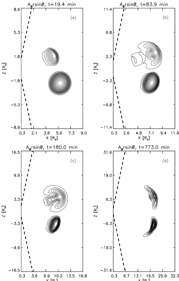
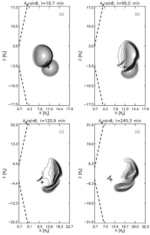
Fig. 1. Contour plots of the vector potential at four times during the evolution of two CMEs whose meridional angle is separated by 40◦. These are projections of the magnetic field on the (r-θ ) plane. The same contour levels are used in all panels.
J. M. Schmidt and P. J. Cargill: A numerical study of two interacting coronal mass ejections 2247
This paper addresses the interaction of CMEs from the viewpoint of magnetohydrodynamic (MHD) simulations. Our aim is to understand the basic processes of the interac-tion: in particular, how does the shock of the trailing CME interact with the leading one; how do the CME magnetic fields interact with each other? Section 2 describes the model briefly: many of the details have been published elsewhere. In Sect. 3 we discuss the interaction between a fast CME that interacts obliquely with a slower and denser CME. In par-ticular, we address the behaviour of shock waves within the slow CME. Section 4 presents a parameter study of CME interactions, with particular emphasis on the relative impact details and magnetic field orientation.
2 The model
We use a MHD simulation model to study the interaction be-tween two CMEs. The details of the equations solved and numerical method used, are outlined elsewhere (e.g. Cargill et al., 2000) and will not to be repeated here. The model is 2.5 dimensional, so that the density and the three compo-nents of the velocity and the magnetic field depend on time
t, the radial distance rand the meridional angle θ , where rotational symmetry is assumed in the φ-direction. We spec-ified a simulation box that extends from 1.7 to 32 Rs: this is
the combined fields of view of the LASCO C2 and C3 coro-nagraphs on board SOHO. In the θ direction the simulation box lies between 10◦and 170◦, with θ =90◦at the equator (see
Fig. 1 for further details).
The two CMEs are assumed to be the coronal manifesta-tion of magnetic clouds, so that they are magnetic flux ropes. In a local cylindrical geometry the field is given by:
Bθ =B0 r/a0 1 + (r/a0)2 , Bz= B0 [1 + (r/a0)2]2 , (1)
(Gold and Hoyle, 1960), where B0is a constant and a0is the
radius of the magnetic cloud. In the initial state we choose the fast and slow CMEs to have B0=0.63 G and 0.5 G,
re-spectively. The fast (slow) CMEs have a0=1.1 (1.5) Rs, and
have initial velocities (vf) of 1095 and 290 km/s,
respec-tively. The centre of the fast and slow CMEs are at r=3.9 and 5.9 Rs. The angle between the meridional positions of
the centers of the initial CMEs can be varied, in order to ex-amine interactions that take place with or without the ICME magnetic fields ever coming into contact.
This choice of B0gives magnetic field strengths of 21 nT
and 42 nT for the fast and slow CMEs, respectively, at 1 AU. The dimensions of the initial CMEs are typical of the dimen-sions of CMEs that are observed with the C2 and C3 corona-graphs of LASCO. The initial velocities are also typical val-ues for fast and slow CMEs, and are also characteristic of the speed of CME pairs seen by Gopalswamy et al. (2001). Since most of the CMEs that have been observed in the LASCO images over-expand when they propagate into the outer in-terplanetary space, a feature that is apparently more common for the faster CMEs (Dere et al., 1999), the slow (fast) CME
was given an initial thermal overpressure of a factor of three (five) with respect to the surrounding solar wind. Finally, the slow CME has its density enhanced by a factor of four with respect to the surrounding solar wind. Density enhancements of this order can be detected by measurements of radio emis-sion in the cores of the CMEs (e.g. Gopalswamy et al., 2001). Both CMEs are placed in a Parker solar wind with a flow speed of 100 km/s at the inner boundary and a sonic point at
r=8.9Rs, so that the two colliding CMEs pass through the
sonic point as they interact. A (radial) solar wind magnetic field is not considered in these simulations.
3 Obliquely colliding CMEs
Figure 1 shows the interaction of two CMEs which have the same (anticlockwise) rotation of the magnetic field, but are separated by 40◦in the meridional plane. In each panel the
x-axis is in the ecliptic plane and the z-axis is the polar co-ordinate of the Sun, each measured in solar radii (note that panels (a) and (b) have different dimensions from the oth-ers). The thick dashed lines denote the inner boundary of the simulation box. The contour-lines of the vector poten-tial Aφrsin θ are plotted in each panel: these are the
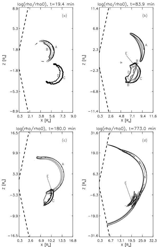
projec-tions of the magnetic field lines onto the x − z-plane. Note also that the whole structure extends out of this plane, i.e. in the φ-direction. Figure 2 shows the plasma density nor-malized locally to its initial value (i.e. ρ (t)/ρ(t=0)), which shows clearly the shock locations. In both plots, quantities are shown at four different times, as indicated on the panels. It is clear from these figures that whereas the magnetic fields of the two CMEs do not interact themselves (there is no reconnection between the two flux systems), the fast CME exerts a major influence on the slow one. The interaction is apparent even in the magnetic field plots, where there is a flattening of the upper side of the slow CME in panel (b), and an associated movement of the centre in a southward di-rection relative to its expected trajectory in the absence of the fast CME. This is due to compressive effects generated by the motion of the fast CME that then hit the slow one. The flattening continues in panel (c) and indeed is exactly opposite to the usual behavior of a CME which undergoes the strongest compression in the radial direction (e.g. Cargill and Schmidt, 2002).
The cause of this distortion becomes clearer from Fig. 2. Both CMEs generate leading shock waves (indicated by la-bels A and C in the panels), due to their relative speed with respect to the solar wind. There is also a density rarefaction in both CMEs due to the mild over-expansion. Finally, as the CMEs start moving, a reverse shock is generated that is con-fined within each CME (labels B and D in the panel). Each pair of forward and reverse shock has a half-moon-like shape and can be seen most clearly in panel (a).
In panel (b) the southern end of the forward shock of the fast CME has begun to interact with the upper boundary of the slow CME, distorting it as seen in the magnetic field plot. This interaction has created a significant pile-up of
2248 J. M. Schmidt and P. J. Cargill: A numerical study of two interacting coronal mass ejections
J. M. Schmidt and P. J. Cargill: A numerical study of two interacting coronal mass ejections 2249
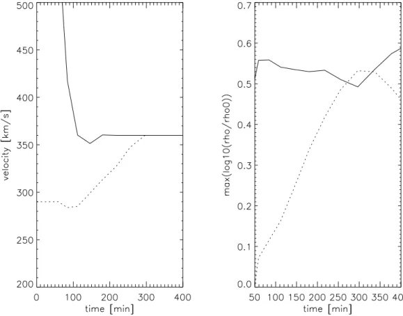
Fig. 3. The velocity (left panel) and shock-strength of the forward shocks (right panel) as a function of time for the fast (solid line) and the
slow (dotted line) CMEs presented in Figs. 1 and 2.
the density at the western leading edge of the slow CME, denoted by the label “E” in the panels. Note that the re-verse shock “B” of the fast CME has penetrated into the slow CME entirely. Where this shock intersects with the forward shock “A” of the fast CME, the latter shock is suppressed, thus creating a gap between the pile-up regions “E” and “A”. There is also a complex process of interaction between the two forward shocks. While colliding, these shocks steepen significantly (see panel (c)). The eastern front of this double-wing-like pattern roughly coincides with the front of the slow CME, i.e. the major part of this shock pattern is within the slow CME. It is obvious that the strong steepening of the fast CME forward shock within the slow CME is due to the en-hanced density which diminishes the Alfv´en speed there.
In panel (d), the strong shock has passed through the slow CME, and is propagating into the undisturbed solar wind, where it displays a nearly spherical pattern. The slow CME has maintained its integrity throughout the interaction, but has undergone considerable distortion (Fig. 1, panel (d)). It is important to note that the slow CME has been accelerated by this interaction, and can now influence the motion of the fast CME. Panel (d) indicates that the southern leading edge of the fast CME is influenced by the northern trailing edge of the slow CME, where solar wind material is sucked into the rear of the slow CME. This edge of the slow CME forms a nose-like pattern that starts in the area denoted by “E” in
panel (d) and extends in the direction of the rear of the fast CME.
The left panel of Fig. 3 shows the velocity of the fast (solid line) and the slow (dotted line) CME. The velocity is de-fined as the velocity at the grid point corresponding to the largest magnetic field intensity in each CME. The “jumpi-ness” in the curves is due to the relatively small number of data points. At the start of the simulation, the fast CME is rapidly decelerated due to its interaction with the solar wind (e.g. Cargill and Schmidt, 2002), and the interaction with the slow CME starts after about 50 min, with a small deceler-ation of the slow CME. Since the fast CME only interacts with the slow CME obliquely, turbulent motions around the sides of the fast CME causes this slight deceleration. After about 100 min, the slow CME is accelerated until it reaches solar wind speed (and speed of the fast CME) after about 300 minutes. At the same time, the fast CME is decelerated initially slightly below solar wind speed, also due to its teraction with the slow CME. It should be noted that the in-teraction of the two CMEs leads to a nearly constant force on the slow CME (the acceleration in the example shown is about 24 km/(min)2).
The right panel of Fig. 3 shows the shock-strength of the forward shock of the fast (solid line) and the slow (dotted line) CME versus time, where the shock-strength is defined as the maximum of the plasma density normalized locally
2250 J. M. Schmidt and P. J. Cargill: A numerical study of two interacting coronal mass ejections
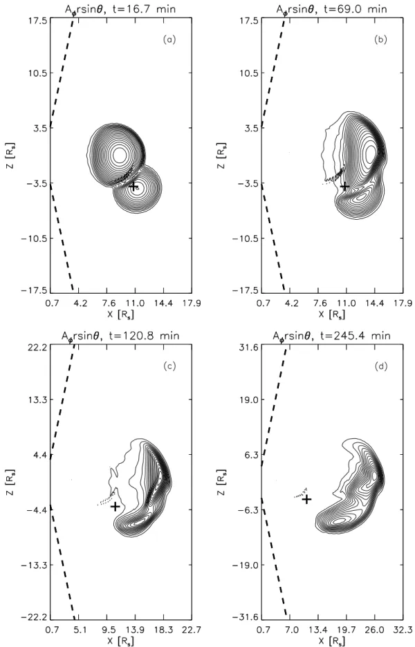
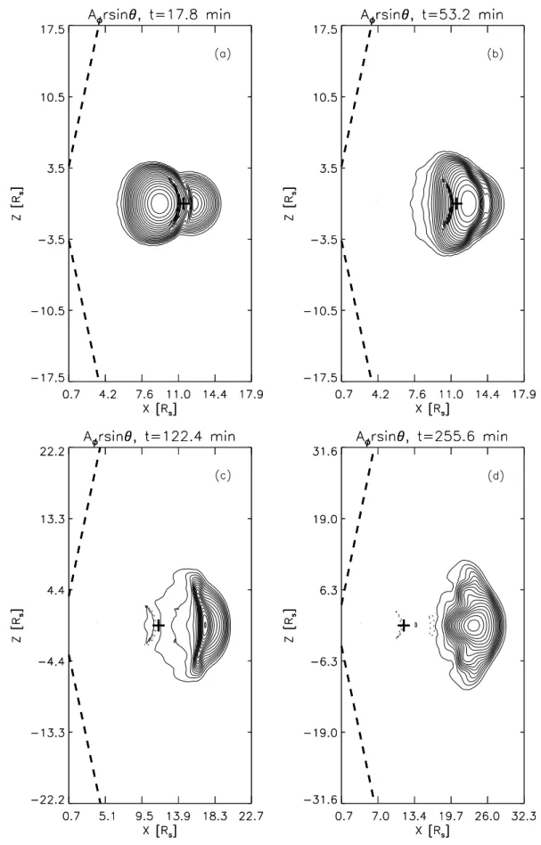
Fig. 4. The magnetic field lines for a case of CME interaction where the two CMEs are initially separated by 20◦in the meridional direction. The two CMEs have the same sense of rotation of their magnetic field.
J. M. Schmidt and P. J. Cargill: A numerical study of two interacting coronal mass ejections 2251
to its initial value ρ(t )/ρ(t =0) throughout the shock. The shock strength of the forward shock of the fast CME de-creases slowly during the interaction up to 300 minutes. Af-ter the inAf-teraction, when the forward shock of the fast CME can propagate freely within the undisturbed solar wind, this shock steepens again. On the other hand, the damping of the forward shock of the fast CME during the interaction leads to a rapid increase of the strength of the forward shock within the slow CME. After about 340 min, the strength of the for-ward shock of the slow CME starts to diminish, since there is no longer a driving force and the effect of the spherical expansion of the plasma of the slow CME is prevailing.
4 Colliding CMEs involving magnetic reconnection
In Sect. 3 we considered a case where the magnetic field of the two CMEs did not interact. Here, we consider a case where the angle of interaction is smaller, such that the mag-netic structures do collide. One can anticipate that the results will depend on the sense of rotation of the CMEs. When the sense of rotation is the same (opposite), magnetic reconnec-tion can (should not) occur when the CMEs collide.
The initial conditions are slightly different from Section 3. The initial position of the fast CME is r=7.8 Rs, θ =90◦and
the slow CME has r=11.7Rs, θ =110◦. The fast and slow
CMEs have initial speeds of 1095 km/s and 290 km/s, respec-tively, Bo=0.14 and 0.072 G, and ao=3.5Rsand 2.9Rs. In the
figures a small cross denotes the position that the centre of the slow CME would have if its propagation was unaffected by the fast CME. Note that these dimensions roughly fit the event that was investigated by Gopalswamy et al. (2001).
The magnetic field lines are shown in Fig. 4. Panel (a) shows, compared with the previous simulation, that there is now a much larger region of direct interaction between the CMEs and that the CMEs in this region become clearly dis-torted because of the impact. In the interaction region, the field lines of the two CMEs reconnect with each other along an extended current sheet. The centre of the slow CME is south of the cross, which shows that the impact has accel-erated the slow CME southward. In panel (b) the fast CME starts to overtake the slow CME. The front part of the fast CME glides over the northern front edge of the slow CME, accelerating the slow CME further in the south-east direc-tion. In panel (c) the fast CME has overtaken the slow CME and both CMEs start to separate. However, the separation is strongly impeded by the extended reconnection of field lines between the two CMEs. This can be seen in panel (d), where there is strong linkage between the northern edge of the front of the slow CME with the interior of the fast CME. Also, the centre of the fast CME has moved further north due to the in-teraction. It can be concluded that strongly interacting CMEs with the same sense of rotation of the field behave like sticky billiard balls, leading to the formation of a single CME. Note that the single CME is now considerably further into the solar wind than the interaction-free location of the slow CME.
Figure 5 shows a simulation that has identical initial condi-tions, but the two CMEs now have an opposite rotation of the field lines. In this case reconnection between the two CMEs is entirely inhibited. Yet we see that many aspects of the in-teraction are similar to Fig. 4, in particular the strong initial impact of the fast CME in panel (a) and the rolling of the fast CME over the northern edge of the slow CME in panel (b). We can conclude that the CMEs in the case of opposite field rotation behave like very elastic billiard balls, since the deformation of the hitting CMEs is quite pronounced.
Finally, Fig. 6 shows results for the overtaking collision of the two CMEs, where the fast and slow CMEs both have their centers initially at θ =90◦, and they have the same sense of field rotation. The CMEs now eventually merge with each other, with the slow CME becoming attached like a cap to the fast CME, as depicted in panel (b). In the middle of the interaction region, where the reconnection of field lines is strongest, the impact of the slow CME pushes the mate-rial at the border of the fast CME into the interior of the fast CME. The associated magnetic field lines acquire an anvil-like shape that seen in its fully developed form in panel (d). Again, the merging of the CMEs is extensive, with the merged internal magnetic field structure showing large de-viations from the original circular shapes. Indeed, this case could be referred to as “CME-cannibalism”.
5 Discussion and conclusions
We have shown that the interaction between CMEs in the solar wind depends on the relative trajectory of the CMEs, as well as on the sense of rotation of the magnetic fields in the CMEs. For cases where the magnetic structures (flux ropes) in the CMEs do not actually collide, the interaction of the CME-related shocks can lead to a net equalization of the CME speeds. This happens when the shock associated with the fast CME passes into and through the slow CME, and accelerates it. When the CMEs interact magnetically, we again find that the slow CME is accelerated up towards the speed of the fast CME, and the two CMEs form a sin-gle body. The magnetic structure of this body is determined by the relative sense of rotation of the magnetic fields in the two CMEs. When the rotation is the same, magnetic recon-nection between the two CMEs occurs, leading to a single, topologically discrete structure. For cases of opposite rota-tion, the two CMEs move together, but their flux systems remain separate. The difference is simply a result of the fact that when the rotations are the same, the magnetic field com-ponents tend to be oppositely directed. We also showed a case of CME cannibalism, where a trailing CME completely absorbed the leading CME.
The implication of these results is that the interaction of pairs of CMEs will tend to lead to large, merged structures, at least when the outward trajectories of the CMEs are close to each other. CMEs do not tend to bounce off each other, but rather stick together. This is a consequence in part of “stick-iness” introduced by the magnetic reconnection process, but
2252 J. M. Schmidt and P. J. Cargill: A numerical study of two interacting coronal mass ejections
J. M. Schmidt and P. J. Cargill: A numerical study of two interacting coronal mass ejections 2253
2254 J. M. Schmidt and P. J. Cargill: A numerical study of two interacting coronal mass ejections
also due to the fact that these are not elastic collisions. The compressibility of the CME (both plasma and magnetic field) means that the CMEs distort around each other, making sep-aration difficult. This merging clearly will lead to more com-plex magnetic field structures, making the interpretation of merged CMEs more difficult at 1 AU. It will also be interest-ing to see whether the merginterest-ing process can lead to periods of intensified Southward Interplanetary Magnetic Field (IMF) at 1 AU, with consequences for geomagnetic activity, but at the present time, observations of CME interactions are re-stricted to limb events. Finally, another issue of interest will be the relationship of such CME interactions to the complex compound streams seen in the outer heliosphere (Burlaga et al., 1986, 1987), which in some cases are associated with large fluxes of energetic particles (Burlaga et al., 1986).
We finally turn to the issue of energetic particles, and the suggestion that CME interaction leads to an enhancement in fluxes of such particles at 1 AU (Gopalswamy et al., 2001; Richardson et al., 2003). It seems probable to us that the ma-jor influence in this regard is in the provision of an enhanced population of “seed particles” which can then undergo shock acceleration. While shock acceleration is a reasonably effec-tive process, the difficulty has always been giving particles the initial energy boost to get it started. Especially as a re-sult of numerical simulations (e.g. Quest, 1988; Scholer and Terasawa, 1990), we now have a reasonable working knowl-edge of how a shock wave can self-inject these seed parti-cles, but the process is slow, and rather selective. It seems clear that if the particles can gain their initial energy from another mechanism, it is likely that one can then accelerate many more particles to high energy at the shock.
We consider magnetic reconnection to be a likely process for this initial energy gain. Magnetic reconnection has many ways to produce accelerated particles (e.g. Miller et al., 1997; Cargill, 2000), including direct electric fields, plasma jets and resultant turbulence, and small localized shocks. The first two are likely to be ubiquitous in most reconnection sce-narios. For the results shown in Fig. 6, we estimate a DC reconnection field of 1 V/m, assuming a relative velocity be-tween the CMEs of 100 km/s and a field strength of 0.1 G. If one requires that the particle velocity be several VA for
in-jection, where VA is of the order of 200 km/s, the injection
energy (of the order of 1 keV) can be reached within 1 km at the reconnection site. Thus, the process is effective and fast. Turbulence is a slower process, since in order to accelerate thermal particles, a cascade is needed to very short wave-lengths (Miller and Roberts, 1995). However, once a proper spectrum of Alfv´en waves has formed, particles can be ener-gized quickly. A proper assessment requires a more rigorous analysis, but reconnection between two CMEs has the poten-tial to energise many particles which the CME-driven shocks can then accelerate.
Acknowledgements. This work was supported in part by the U.K. Particle Physics and Astronomy Research Council. PC also ac-knowledges the support of a PPARC Senior Research Fellowship. Topical Editor in chief thanks U. Bothmer for his help in evalu-ating this paper.
References
Burlaga, L. F.: Magnetic clouds: Constant alpha force-free config-urations, J. Geophys. Res., 93, 7217–7224, 1988.
Burlaga, L. F., MacDonald, F. B., and Schwenn, R.: Formation of a compound stream between 0.85 AU and 6.2 AU and its effects on solar energetic particles and galactic cosmic rays, J. Geophys. Res., 91,3331–3340, 1986.
Burlaga, L. F., Behannon, K. W., and Klien, L. W.: Compound streams, magnetic clouds, and major geomagnetic storms, J. Geophys. Res., 92, 5725–5734, 1987.
Cargill, P. J.: Solar flares: Particle acceleration mechanisms, in en-cyclopedia of astronomy and astrophysics, Ed. P. Murdin, 2546, 2000.
Cargill, P. J., Schmidt, J. M., Spicer, D. S., and Zalesak, S. T.: The magnetic structure of over-expanding CMEs, J. Geophys. Res., 105, 7509–7519, 2000.
Cargill, P. J. and Schmidt, J. M.: Modelling interplanetary CMEs using magnetohydrodynamic simulations, Ann. Geophys., 20, 879–890, 2002.
Dere, K. P., Brueckner, G. E., and Howard, R. A. et al.: LASCO and EIT observations of helical structure in coronal mass ejections, Astrophys. J., 516, 465–474, 1999.
Gold, T. and Hoyle, F.: On the origin of solar flares, Mon. Not. R. Astron. Soc., 120, 89, 1960.
Gopalswamy, N., Yashiro, S., Kaiser, M. L., Howard, R. A., and Bougeret, J.-L.: Radio signatures of coronal mass ejection inter-action: Coronal mass ejection cannibalism?, Astrophys. J., 548, L91–L94, 2001.
Gopalswamy, N., Yashiro, S., Michalek, G., Kaiser, M. L., Howard, R. A., Reames, D. V., Leske, R., and von Rosenvinge, T.: Inter-acting coronal mass ejections and solar energetic particles, As-trophys. J., 572, L103–L107, 2002.
Hundhausen, A. J.: Coronal mass ejections, in: The many faces of the sun, (Eds) Strong, K. T. et al., Springer, 143, 1999.
Miller, J. A. and Cargill, P. J., and Emslie, A. G. et al.: Critical issues for understanding particle acceleration in impulsive solar flares, J. Geophys. Res., 102, 14 631–14 659, 1997.
Miller, J. A. and Roberts, D. A.: Stochastic proton acceleration by cascading Alfv´en waves in impulsive solar flares, Astrophys. J., 452, 912–932, 1995.
Quest, K. B.: Theory and simulation of collisionless parallel shocks, J. Geophys. Res., 93, 9649–9680, 1988.
Richardson, I., Lawrence, G. R., Haggerty, D. K. et al.: Are CME “interactions” really important for accelerating ma-jor solar energetic particle events?, Geophys. Res., Lett., 10.1029/2002GL016424, 2003.
St Cyr, O. C., Howard, R. A., Sheeley, N. R. et al.: Properties of coronal mass ejections: SOHO LASCO observations from Jan-uary 1996 to June 1998, J. Geophys. Res., 105, 18 169–18 185, 2000.
Scholer, M. and Terasawa, T.: Ion reflection and dissipation at quasi-parallel collisionless shocks, Geophys. Res. Lett, 17, 119– 122, 1990.