Publisher’s version / Version de l'éditeur:
Transportation Research Record, 612, pp. 80-83, 1976
READ THESE TERMS AND CONDITIONS CAREFULLY BEFORE USING THIS WEBSITE.
https://nrc-publications.canada.ca/eng/copyright
Vous avez des questions? Nous pouvons vous aider. Pour communiquer directement avec un auteur, consultez la
première page de la revue dans laquelle son article a été publié afin de trouver ses coordonnées. Si vous n’arrivez pas à les repérer, communiquez avec nous à [email protected].
Questions? Contact the NRC Publications Archive team at
[email protected]. If you wish to email the authors directly, please see the first page of the publication for their contact information.
NRC Publications Archive
Archives des publications du CNRC
This publication could be one of several versions: author’s original, accepted manuscript or the publisher’s version. / La version de cette publication peut être l’une des suivantes : la version prépublication de l’auteur, la version acceptée du manuscrit ou la version de l’éditeur.
Access and use of this website and the material on it are subject to the Terms and Conditions set forth at
Insulated road study
Penner, E.
https://publications-cnrc.canada.ca/fra/droits
L’accès à ce site Web et l’utilisation de son contenu sont assujettis aux conditions présentées dans le site LISEZ CES CONDITIONS ATTENTIVEMENT AVANT D’UTILISER CE SITE WEB.
NRC Publications Record / Notice d'Archives des publications de CNRC:
https://nrc-publications.canada.ca/eng/view/object/?id=cb4861aa-dc1b-4dc4-b36a-bca56b8a1ef0 https://publications-cnrc.canada.ca/fra/voir/objet/?id=cb4861aa-dc1b-4dc4-b36a-bca56b8a1ef0
--
a
Ser
TH1
N21d
no.
733
I
c * 2National Research Council of Canada
I
BLDGConseil national de recherches du Canada
ANALYZED
INSULATED ROAD STUDY
by
E.
Penner
5
Reprinted from
Transportation Research R.ecord
612
1976,
p.
80-83
DBR
Paper No.
733
Division of Building Research
SO
MMAIRE
L e s rCsultats d'une Ctude de t r o i s a n s s u r un c h e m i n calorifugk
montrent que l a pCnCtration du g e l v e r s l ' i n t k r i e u r depuis l e
b o r d d'une zone calorifugCe Cquivaut
'a
peu pr'es
'a
l a pCnCtration
v e r s l e b a s d a n s une s e c t i o n contr6lCe. L'humiditC c ' e s t
accumulCe dans l ' i n f r a s t r u c t u r e gClive l o r s q u e l e f r o n t de g e l
a pCnCtrC l ' i s o l a n t . E n c a s d e r e f r o i d i s s e m e n t r a p i d e , l a
b a i s s e de t e m p C r a t u r e
'a
l a s u r f a c e de l a c h a u s s k e peut
entra7ner l e g i v r a g e de l a s u r f a c e l o r s q u e l e s conditions
dlhumiditC atmosphkrique s l y prEtent. Une couche d ' i s o l a n t
qui s e t e r mine b r u s q u e m e n t s a n s e n c a s t r e m e n t provoque d e s
changements a b r u p t s du niveau de l a chaussCe p a r s u i t e du
gonfle ment.
Insulated Road Study
E. Penner, Division of Building Research, National Research Council of Canada
The results of a 3-year insulated road study showed that frost penetration inward from the edge of an insulated area is about the same as the down- ward penetration on a control section. Moisture accumulated in the frost- susceptible subgrade after the frost line penetrated the insulation. During periods of rapid cooling, the temperature of the surface above an insu- lated pavement may be lowered sufficiently to permit surface icing if at- mospheric moisture conditions are suitable. Terminating the insulation without feathering induces abrupt changes in elevation in the roadway as a result of heaving.
Thermally insulated roads attenuate frost penetration in winter by reducing ground heat loss to the air. The pavement thickness of such roads can be reduced in a r e a s where frost penetration and i t s subsequent damage a r e critical factors. Since base course material'is be- coming scarce in some a r e a s , the use of insulation may reduce the cost of road construction.
Insulated road sections have been constructed in Canada and the northern regions of the United States (1,
&,T,
,4,2).
In Ontario insulation is now used a s a stan-dard method for repairing frost-damaged highway sec- tions, although i t has not yet been used in new highway construction. The information in the literature is still sparse on some aspects of the field performance of in- sulated roads despite the general acceptance of the tech- nique for the fast and efficient repair of busy highways. Among the l e s s understood aspects a r e (a) the extent of ice lensing when the frost line penetrates and remains below the insulation layer in frost-susceptible soil for a considerable period and (b) the thermal pattern in the soil a t the transition zone between the insulated and un- insulated sections.
The f i r s t is particularly significant i f an insulated section has been underdesigned, either in e r r o r because of a lack of a i r temperature information or intentionally to keep construction costs a s low a s possible o r to de- crease the likelihood of surface icing. Information about the thermal regime a t the transition zone is important
Publication of this paper sponsored by Committee on Frost Action.
for extending the insulation a sufficient distance beyond the protected a r e a to prevent abrupt changes in elevation a t the ends.
SOIL CONDITIONS
The experimental work was conducted on the grounds of the National Research Council of Canada in Ottawa. The soil is a postglacial clay of marine origin that is com- monly referred to a s Leda clay (6). It consists of about 70 percent clay-size and 30 percgnt silt-size particles. F r o s t heaving is approximately 9 to 12 cm (0.3 to 0.4 ft) during most winters in snow-cleared areas.
DESIGN OF INSTALLATION
Figure 1, a plan of the 30.5-m (100-ft) test road, shows the location of the instrumentation, which consists of thermocouple strings, survey plates, and access holes for neutron moisture measurements. The pavement de- sign for the 15-m ( 5 0 4 ) insulated section is shown in Figure 2. The procedure for preparing the subgrade for placement of the insulation boards was to fine grade it, then hand rake the surface. The 0.6 by 1.2-m (2 by 4 4 ) insulation boards were staggered and held in place with 15-cm (6-in) wooden dowels. The crushed rock base was end-dumped from trucks and spread by hand. MEASUREMENT TECHNIQUES
Temperatures were measured by 0.8-mm (20-gauge) copper-constantan thermocouples attached to 4-cm (1.5-in) diameter wooden dowels. A 0.3-m (1-ft) length of thermocouple lead was wrapped around the dowel in a groove a t each measurement position to minimize con- duction e r r o r s . At each location in the control section a t which temperatures were measured, thermocouples were placed 0.076, 0.3, 0.6, and 1.2 m (3, 12, 24, and 48 in) from the surface; in the insulated section thermo- couples were placed 0.076, 0.2, 0.3, 0.6, and 1.2 m (3,
10, 12, 24, and 48 in) from the surface.
Subgrade moisture contents were determined with a neutron moisture meter near the center of each section (7,8). The access holes of the neutron meter probe were
- -
cased with 4-cm (1.5-in) diameter aluminum tubes locations shown in Figure 1 and referenced to a stable
sealed with rubber stoppers; desiccant was kept inside benchmark.
the tubes to prevent moisture condensation on the inner
walls. Elevation surveys for heave measurements were RESULTS AND DISCUSSION
carried out with a precise level on metal plates em-
bedded in the surface of the asphaltic concrete a t the The thermal pattern for the time of maximum frost pene-
Figure 1. Plan of test road. I N S T R U M E N T
HUT i
I
L - - -- -
- - -- - -
- - - - -I h ,f .
" . . . . - A. X . X I x I bl .22m1
, . .
Ir-3
1 3.35m ' 4 .in.-
>: L . - - . M 0 ;-
2 PAVED W I D T H " ) ( 4 ) 131 121 I I 11
C R U S H E D R O C K S H O U L D E R , . - . - .e
C O N T R O L 5 0 ' - 1 5 . 2 m I N S U L A T E D 5 0 ' - I 5 . 2 m0 THERMOCOUPLE S T R I N G S C CASED ACCESS H O L E S FOR N E U T R O N MOISTURE MEASUREMENTS
X E L E V A T I O N SURVEY PLATES - - THERMOCOUPLE CABLE
Figure 2. Cross section of
insulated road section.
i
r
SLOPE 0 . 3 " / F O O T - 2 .5cm/mi
/
,
SLOPE 0 . 5 " / F O O T - 4 . I c m / mFigure 3. Isotherms near time of maximum frost penetration at end of insulated section on centerline of snow-cleared road. D I S T A N C E F R O M EDGE O F I N S U L A T I O N , m THERMOCOUPLES P O S l T l O N E AT 7.6 cm 0.2m 0.3 m 0.45 rn 0.6 m F . I . 1 3 5 2 D E G R E E - D A Y S , " F 7 4 8 D E G R E E - D A Y S , "C I N S U L A T E D N O T I N S U L A T E D D I S T A N C E F R O M EDGE O F I N S U L A T I O N , FEET
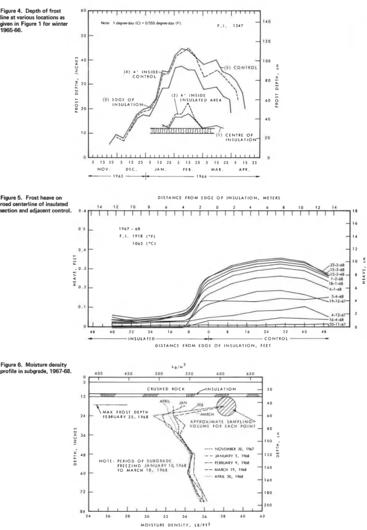
Figure 4. Depth of frost line at various locations as given in Figure 1 for winter
I
Now 1 degreeday 1.1 = 0.555 degreeday ~ F I .1965-66. ( 4 ) 4 ' I N S I D E 13) E D G E O F I N S U L A T I O N C E N T R E O F I N S U L A T I O N - I 1 l f l [ l l l l t l i l l l l I 1 l l l l l l 1 l l l l j l l l t 5 15 25 5 15 25 5 15 25 5 15 25 5 15 2 5 5 15 25 N O V . D E C . J A N . FE B M A R . A P R . 1 9 6 5
a
1 9 6 6Fiaure 5. Frost heave on D I S T A N C E F R O M E D G E O F I N S U L A T I O N , M E T E R S
road centerline of insulated 1 4 1 2 10 0 6 4 2 0 2 4 6 8 1 0 1 2 1 4
section and adjacent control. 0 , 6
1 1 1 1 1 1 1 1 1 1 1 1 1 1 1 1 1 1 1 l l l l l l l l i
I N S U L A T E D I C O N T R O L D I S T A N C E F R O M E D G E O F I N S U L A T I O N , FEET
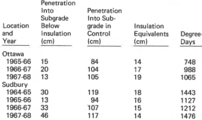
Figure 6. Moisture density profile in subgrade, 1967-68. 0 3
I
C R U S H E D R O C K / I N S U L A T I O N-1
2 0 F E B R U A R Y 2 5 , 1 9 6 8I
N O T E :"\
---- NOVEMBER 30, 19671
P E R I O D O F SUBGRADE F R E E Z I N G J A N U A R Y 10, 1988 FEBRUARY 9. 1968 T O M A R C H 1 8 . I P b B I , -- M O I S T U R E D E N S I T Y , L B / F T ~tration, a t the transition zone between the insulated and control sections on the road centerline, was similar for the 3 consecutive years, 1965-66, 1966-67, and 1967-68.
Figure 3 gives such a pattern for 1 year. The base
course above the insulation was colder than the surface of the control section, but differences in the tempera- tures of the surfaces would depend on the a i r tempera- ture prior to the measurements. The thermal response of the base course above the insulation to changes in the a i r temperature gave warmer temperatures for the in- sulated sections in the summer and colder temperatures in the winter.
Figure 4 shows the frost penetration a t the edge of the insulation 1.2 m (4 ft) inside the insulated area, 1.2 m (4 ft) inside the control area, and a t the center of each section. In all cases, the frost penetration a t the center of the control a r e a and that at a point 1.2 m (4 ft) from the edge of the insulation were similar. During the 3-year period when the measurements were made, the frost penetration in the control a r e a ranged from about 1.1 to 1.5 m (45 to 55 in). Thus, a t a distance inside the insulated a r e a equal to the depth of frost penetration a l - most all end effects due to insulation have disappeared.
The heave pattern for the three winters shows the severity of frost heave in Leda clay. Figure 5 gives the results for 1967-68. Heaving was observed in the insulated a r e a a s well a s in the control section since 5 cm (2 in) of insulation does not provide complete frost protection for the subgrade. The water table a t the site characteristically r i s e s to the ground surface in the fall;
a s the surface of the pavement is levelwiththe surround-
ing terrain, this results in a fully saturated base course. The small heave above the insulation measured during
the period of freezing is attributed solely to expansion
of water. Normal ice lens growth is thought to be re- sponsible for the measured heave that takes place after the frost line has passed through the insulation into the subgrade. The measure of moisture increase below the insulation is given in terms of moisture density in Fig- u r e 6, which also shows the position of the frost line a t a maximum penetration in relation to the depth a t which the moisture was measured.
Two final items a r e of particular interest. The ther- mal equivalents of soil versus insulation for the Ottawa t r i a l s and for those a t another test site in Sudbury, On- tario, a r e shown in the table below, which also lists the cumulative d e g r e e d a y s for each year a t each site.
Location and Year Ottawa 1965-66 1966-67 1967-68 Sudbury 1964-65 1965-66 1966-67 1967-68 Penetration lnto Subgrade Below Insulation (cm) 15 20 13 30 13 33 46 Penetration lnto Sub- grade in Control (cm) 84 104 105 119 94 107 117 Insulation Equivalents (cm) 14 17 19 18 16 15 14 Degree- Days 748 988 1065 1443 1127 1212 1476
The values range from 14 to 19 cm of soil p e r centimeter of insulation. The average thermal conductivity of the in- sulation (measured'in the laboratory) was 0.39 W / ~ . K (0.27 ~tu.in/h.ff. OF) after 10 y e a r s burial a t the Ottawa test site. After 6 weeks drying a t 41°c (105'~) this
value was reduced to 0.35 W / ~ . K (0.24 Btu.in/h.ft2. OF).
The moisture absorbed and retained was 6.8 percent by volume, which appears entirely acceptable after 10 years of exposure in the ground.
CONCLUSIONS
Although the heat extraction rate is slow when the frost
line is in wet frost-susceptible soil below insulation,
moisture flow is induced and heaving occurs. Under the soil and climatic conditions of this study, frost penetra- tion inward from the edge of the insulation was about the same a s that downward in an uninsulated area. Abrupt heaving a t the edge of the insulation was well demonstrated and can be avoided by feathering the insulation a t the ends of the insulated sections.
ACKNOWLEDGMENTS
The author wishes to express his appreciation to his colleagues for assisting with the work carried out in this study and for their many helpful suggestions. This paper
is a contribution from the Division of Building Research,
National Research Council of Canada, and is published
with the approval of the director of the division. REFERENCES
1. Performance Study Report on Insulation Board (Poly-
styrene). AASHO-ARBA Subcommittee on Develop- ment, Evaluation, and Recommendation of New High- way Materials, 1970.
2. M. D. Oosterbaan and G. A. Leonards. Use of Insulating Layer to Attenuate Frost Action in Highway Pavements. HRB, Highway Research Record 101,
1965, pp. 11-27.
3. F. D. Young. Experimental Foamed Plastic Base Course. HRB, Highway Research Record 101, 1965, pp. 1-10.
4. E. Penner, M. D. Oosterbaan, and R. W. Rodman. Performance of City Pavement Structures Containi'ng Foamed Plastic Insulation. HRB, Highway Research Record 128, 1966, pp. 1-17.
5. E. Penner. Experimental Pavement Structures In- sulated With a Polyurethane and Extruded Polystyrene Foam. Proc., International Conference on Low Tem-
perature Science, Sapporo, Japan, Vol. 1, P a r t 2,
1967, pp. 1311-1322.
6. C. B. Crawford. Quick Clays of Eastern Canada. Engineering Geology, Vol. 2, No. 4, 1968, pp. 239- 265.
7. K. N. Burn. Design and Calibration of a Neutron Moisture Meter. ASTM, STP 293, 1961, pp. 14-26. 8. K. N. Burn. Calibration of a Neutron Moisture
Meter in Leda Clay. Canadian Geotechnical Journal,