HAL Id: hal-03116437
https://hal.archives-ouvertes.fr/hal-03116437
Submitted on 7 Apr 2021
HAL is a multi-disciplinary open access
archive for the deposit and dissemination of
sci-entific research documents, whether they are
pub-lished or not. The documents may come from
teaching and research institutions in France or
abroad, or from public or private research centers.
L’archive ouverte pluridisciplinaire HAL, est
destinée au dépôt et à la diffusion de documents
scientifiques de niveau recherche, publiés ou non,
émanant des établissements d’enseignement et de
recherche français ou étrangers, des laboratoires
publics ou privés.
A new method for quantitative analysis of helium
isotopes in sediment pore-waters
Carine Chaduteau, Elise Fourré, Philippe Jean-Baptiste, Arnaud Dapoigny,
Dominique Baumier, Jean-Luc Charlou
To cite this version:
Carine Chaduteau, Elise Fourré, Philippe Jean-Baptiste, Arnaud Dapoigny, Dominique Baumier, et
al.. A new method for quantitative analysis of helium isotopes in sediment pore-waters. Limnology
and Oceanography: Methods, Association for the Sciences of Limnology and Oceanography, 2007, 5
(11), pp.425-432. �10.4319/lom.2007.5.425�. �hal-03116437�
Noble gases have been used successfully for several decades in studies of groundwater dynamics and paleoclimate (Kipfer et al. 2002). However, in spite of the likelihood that sediment pore waters may provide high resolution noble gas archives of pale-oenvironmental and paleoceanographic changes, they have not been analyzed widely for this information because of difficulties in collecting samples without gas loss and/or contamination problems. For example, severe gas loss was indicated in an early attempt to measure noble gas concentrations in pore fluids of some Deep-Sea Drilling Project (DSDP) sediment cores that were squeezed after recovery (Broecker 1973), yet the presence of excess helium could be qualitatively demonstrated (Clarke et al. 1973). Sano et al. (1992) developed an alternative sampling technique to withdraw and collect gases through core liners using a glass syringe with a stainless steel needle, but they
obtained only reliable isotopic and elemental ratios (3He/4He
and 4He/20Ne) without quantitative concentration data.
Alternatively, in-situ sampling also was explored. During the DSDP, Barnes developed tools designed to sample gases in sedimentary pore fluids through a probe extending ahead of the drilling bit (Barnes 1973, 1988). Torres et al. (1995) used an improved version of this tool, known as the Water Sampler-Temperature-Pressure (WSTP) and concluded that gas bubbles significantly affected measured noble gas concentrations. Moreover, this equipment was rather complex to operate, could be deployed only on drilling programs, and was able to recover only one sample per cast.
To study dissolved helium in lake sediment pore-waters, Stephenson et al. (1994) improved the in-situ probe by using ping-pong balls (Dyck and Da Silva 1981) as semi-permeable gas samplers that equilibrate with the surrounding environ-ment. However, the system needed to be left in the sediment for at least 4 d to get a complete equilibration between helium in the ball and in the pore-water. Moreover, the probe was not suitable for water depths exceeding 55-m because the balls could not withstand greater hydrostatic pressures.
It is only recently that ship-based sampling has been revis-ited. Brennwald et al. (2003) designed a new method for the quantitative sampling and extraction of dissolved noble gases from sediment cores. Bulk sediment was transferred by
squeez-A new method for quantitative analysis of helium isotopes in
sediment pore-waters
Carine Chaduteau
1,2, Elise Fourré
1, Philippe Jean-Baptiste
1, Arnaud Dapoigny
1, Dominique Baumier
1, and Jean-Luc Charlou
2 1LSCE/IPSL, Laboratoire CEA-CNRS-UVSQ, Gif-sur-Yvette, France; 2Laboratoire de Géochimie et Métallogénie IFREMER, Plouzané, FranceAbstract
Owing to their inertness and contrasted composition in the various earth reservoirs, helium isotopes are powerful tracers of a number of processes pertaining to geophysics and geochemistry. Because sediments cover a large portion of the earth’s surface, helium isotope geochemistry of sediment pore-waters is of particular interest. In spite of this potential, its development has been hampered by the difficulty of collecting samples without gas loss and/or contamination problems. We developed a new method for the sampling and the quantitative extraction of dissolved helium from sediment pore-waters, leading to the determination of 3He and 4He
con-centration profiles. Core sampling is non-destructive (no squeezing). The principle of the method is to use stan-dard copper tubes (1.2 cm OD/25 cm in length), subsequently sealed with clamps, to take mini-cores along the sediment core immediately following its retrieval. In the lab, the sediment is transferred from the copper tube to a noble gas extraction line by applying pressurized helium-free water at one end of the copper tube. This tech-nique allows dissolved helium to be recovered and analyzed using standard procedures for water samples. Tests were carried out successfully on an artificial core equilibrated with air to check the extraction efficiency in the same conditions as for real cores. The validity of the method was further confirmed by acquiring a vertical heli-um profile from a real marine core from the Zaire deep-sea fan, illustrating some possible applications.
Elise Fourré, LSCE/Orme des merisiers, 91191 Gif-sur-Yvette cedex, France ([email protected]).
Acknowledgments
This work was funded by the CEA and IFREMER. ZaiRov Leg 2 cruise was funded through the ZAIANGO project of cooperation between TOTAL and IFREMER. We thank Hélène Ondréas, the chief scientist, Jean-Pierre Donval and Gilbert Floch for the core handling, and Henri Bougault who inspired this work and collected the helium samples. We are grateful to the associate editor Clare Reimers and to two anonymous reviewers for their helpful reviews and valuable comments.
Limnol. Oceanogr.: Methods 5, 2007, 425–432
© 2007, by the American Society of Limnology and Oceanography, Inc.
and
ing the sediment core into standard copper tubes placed per-pendicular to the core and connected to the core liner via Swagelok fittings. Although this simple method avoids gas losses and contamination during sampling, the procedure is destructive for the core and does not allow any physical mea-surement or additional sampling of the core for other applica-tions. Moreover, as acknowledged by the authors, it is not adapted for helium because the strong heating (250°C) required to blow the sediment out of the copper tube into the extraction vessel causes the release of radiogenic helium from sediment minerals. Hence, this method is not directly applicable to our purpose which is to develop helium isotope geochemistry of sediment pore-waters, following the work done particularly on
3He excess in free ocean waters in the past decades.
Specifically, following the discovery of large scale oceanic plumes of mantle 3He derived from hydrothermal activity at
mid-ocean ridges, helium isotopes have proven to be excellent tracers of the oceanic circulation, water mass formation and ventilation processes (Farley et al. 1995; Schlosser and Winck-ler 2002; Dutay et al. 2004). This oceanic 3He distribution
should also be archived in pore-waters during sediment for-mation. Hence, our prime motivation for developing a new method was to be able to use paleo-3He excesses in marine
sed-iments as an alternative paleoceanographic tool to 14C to
determine reservoir ages and to provide useful constraints on past oceanic ventilation rates and paleo-circulation, applying the same philosophy as that developed for paleo-salinities and paleo-δ18O (Schrag et al. 1996; Adkins et al. 2002). Here, we
describe a new method for the sampling and quantitative extraction of dissolved helium from sediment pore-water. This method recovers quantitative helium concentration and 3He/ 4He isotopic ratio profiles from sediment cores by non-destructive
sampling at various depths, thus opening sediment pore-waters to helium isotope geochemistry.
Materials and procedures
Sediment sampling—In theory, shipboard noble gas
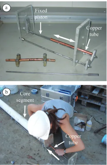
sam-pling after core recovery could induce possible artifacts associ-ated with pressure and temperature changes. However, Bren-nwald et al. (2003) have shown from their tests on lacustrine sediments (recovered at 72-m and 116-m water depth with a bottom water temperature of 4.5°C) that shipboard sampling had no adverse effect on pore-water noble gas concentrations and isotopic ratios. Hence, shipboard sampling was preferred to in-situ techniques because of its far lower degree of com-plexity. The principle of our sampling technique is to use cop-per tubes (1.2 cm OD, 25 cm in length) equipped with a small piston to take mini-cores along the sediment core immedi-ately following its retrieval and cutting into sections, prior to any other core manipulation. The mini-cores can be taken either parallel or perpendicular to the core axis depending on the type and diameter of core. Thus, the sampling interval can be adapted to the required temporal resolution. For piston cores, which are cut in manageable lengths and later split, a
sampler with a fixed piston is used to core horizontally both ends of each core segment by pushing the copper tube into the sediment manually (Fig. 1a and Fig. 2). The mini-core is collected away from the axis and a plastic rod is used to plug the hole made by the mini-core to avoid further disturbance of the sediment. Thus, our sampling procedure is basically non-destructive and can be coupled with other geochemical samplings, physical measurements, and sedimentological description. For box cores, the sampling procedure is similar, but the piston is attached vertically to a support which is moved along the core at the desired locations (Fig. 1b).
Immediately after its retrieval, the copper tube is sealed with metallic clamps (Weiss 1968) placed a conservative 5 cm inward from both ends to avoid air contamination that may occur at the open ends of the core segment during the sampling time, which is typically a few min in duration. A simple diffusion cal-culation using, as a conservative estimate, the diffusion coeffi-cient of helium in free water (Jähne et al. 1987) i.e., without tak-ing into account the sediment tortuosity, shows that the depth
Chaduteau et al. He isotopes in sediment pore-waters
Fig. 1.(a) Horizontal sampling on a piston core segment: a copper tube sliding on a fixed piston is pushed manually into the sediment at each end of the segment. (b) Vertical sampling on a box core.
below the surface affected by diffusion is only 9 mm after 15 min and 17 mm after 1 h. Copper tubes sealed with clamps are used routinely by many labs to take water samples for gas analysis. The measured helium leak rates for clamps with and without sediment (Table 1) show that the tightness of the system is not adversely affected by the mineral grains of marine sediments at the inner surface of the copper tube.
Extraction of the dissolved helium—The direct application of
the method used in the lab to extract helium dissolved in nat-ural waters (Jenkins 1976) proved to be inadequate to extract helium from the bulk sediment because pore-water is embed-ded and trapped in the solid phase of the sediment. Several tests were performed on our standard water extraction line without extruding the sediment from the copper tube. At room temperature, the reproducibility of the extraction efficiency was poor. By heating the copper tube up to 150°C with a heat-ing tape, the amount of helium recovered was substantially
higher and more reproducible, but the 3He/4He ratio dropped
substantially indicating some release of radiogenic helium from the sediment minerals. Therefore, a special line was devel-oped to extract the dissolved helium from the sediment pore-water (Fig. 3). The general idea is to use pressurized helium-free water to push the sediment out of the copper tube into a glass flask equipped with a high vacuum CF-flange, where the sedi-ment sample and the water mix and turn into a liquid slurry; the procedure for transferring helium from this slurry into the
Fig. 2.(a) From bottom to top: the piston, a sediment sample in a cop-per tube pinched by metallic clamps and the sampler with a copcop-per tube sliding on the fixed piston. (b) Horizontal sampling on a core segment by pushing manually a copper tube into the sediment.
Fig. 3.Schematic diagram of the line specifically designed to extract dis-solved helium from sediment pore-waters (Inset: Temperature transient during the extrusion of the sediment from the copper tube with hot pres-surized water – see text).
Table 1.
Measured helium leak rates for copper tubes sealed with metallic clamps. Before sealing, tubes were either empty or filled with water or sediment. Pure helium was applied behind the clamp at the outer end of each tube before the leak rates were measured with a MAP 215-50 noble gas mass spectrometer attached in line. (For comparison, the typical helium leak rate guaranteed for high vacuum valves is ∼10–9cm3STP/atm/s)Sealed Sealed Sealed
copper copper tube copper tube tube with water with sediment
Helium leak rate 3.8 × 10⁻¹¹ – –
(in cm3STP/atm/s) 5.9 × 10⁻¹³ 6.2 × 10⁻¹³ 2.3 × 10⁻¹¹
Corning glass bulb which will be analyzed on the mass spec-trometer is then similar to the procedure routinely used for water samples in the lab (Jean-Baptiste et al. 1992). In detail, the extraction procedure consists of the steps outlined below.
Step 1.
The first step of the extraction procedure is to degas the water which will be pressurized to push the sediment. For this procedure, a stainless steel container (325 mL) equipped with a Nupro valve (ref 6LW-DPHFR4) is filled with 125 cc of deminer-alized water. The container is then connected to a vacuum unit with an oil diffusion pump protected by a cold trap kept in liquid nitrogen. The water, which is kept in a warm bath to prevent freezing, is pumped for 40 min (down to 10–6Torr) while being
stirred with a magnetic bar. Then the container is closed and attached to the sediment extraction line via a Cajon fitting.
Step 2.
During the 40 min of the Step 1, the ends of the copper tube with the sample are cleaned before soldering the tube with tin to the extraction line (Fig. 3). During soldering, the copper tube and the clamps are protected by wet tissues to keep the sample at room temperature and to avoid any ther-mal disturbance of the sediment. When ready, the extraction line is evacuated down to 10-6Torr for at least 2 h.
Step 3.
To start the extraction, the line is isolated from the vacuum unit. The valve of the stainless steel container is opened to allow the degassed water to fill a small copper cylinder (70 mL) located right below (Fig. 3) and then closed again. The clamps are removed and the copper tube is reopened with a pair of pliers. Then, the copper cylinder with the degassed water is flame-heated. Within a few minutes, the pressure in the copper cylin-der is sufficient to blow the sediment out of the tube down into the glass flask. In the first tests, because of the rapidity of the sed-iment extrusion, some sedsed-iment slurry sprayed into the extrac-tion line. To prevent this, we added a cap actuated from outside through a stainless steel bellow designed to obturate the extrac-tion line during the blowing phase. The glass flask is kept from the beginning in an icy bath to reduce the time during which the sediment is exposed to hot water. The inset in Fig. 3 shows the thermal transient in the glass flask (measured with a small thermocouple on a special experiment). The temperature of the sediment/water mixture reaches a maximum of 70°C for a frac-tion of a second and drops rapidly afterward. Within about 40 s, the temperature falls below 40°C. After 2 min, the temperature of the slurry is less than 30°C. As far as the copper tube is
con-cerned, its temperature does not significantly depart from the ambient temperature. Thus the thermal shock to the sediment caused by the hot pressurized water during the extrusion phase is minimal and is not expected to cause any thermal release of radiogenic helium from minerals. By contrast, in the Brennwald et al. (2003) method, the temperature is raised up to 250°C to blow out the sediment into the extraction vessel. The fact that the sample is not affected adversely by the hot pressurized water is confirmed by the lack of radiogenic helium on the various tests performed to validate the extraction procedure (see below).
Step 4.
In the glass flask, the sediment/degassed water mixture is liquid (liquid mud). Hence helium can be extracted using the same procedure as we use for water samples (Jean-Baptiste et al. 1992). Briefly, the Corning glass bulb used to collect the gases is put in a liquid nitrogen Dewar while the sediment/ water mixture in the glass flask is stirred with a magnetic bar. A capillary, placed just above the bulb, prevents any back-diffusion of helium in the line. After 15 min, the Corning glass bulb containing the extracted helium is flame-sealed.
The mass of the sediment sample is determined by weigh-ing the copper tube full and empty at the beginnweigh-ing and at the end of the procedure. The mud in the glass flask is dried to obtain the mass of dry sediment. The mass of the pore-water is thus given by the mass difference (around 9 g for the ZaiAngo samples presented below).
Finally, the Corning glass bulb is analyzed for helium and neon isotopes on a MAP 215-50 noble gas mass spectrometer using our standard procedure (Jean-Baptiste et al. 1992).
Assessment
Line blanks—To test the leak rate of the extraction line, an
empty copper tube replaced the sample and the evacuated line stayed isolated 30 min, to simulate a normal extraction. Then, the Corning glass bulb was sealed and analyzed on the mass spectrometer. The mean blank measured on five experiments is 1.3 ± 0.1 × 10⁻⁹cm3STP for 4He and 1.6 ± 0.2 × 10⁻¹⁵cm3STP
for 3He.
To determine the total blank of the extraction procedure (including the blank of the degassed water), several extrac-tions were performed with an empty copper tube closed with only one clamp at the top end, in place of the sample. Thanks to this clamp, the copper cylinder could be filled with degassed water and the full extraction procedure (without sed-iment) could be simulated. The total extraction blank, 4.6 ± 0.2 × 10⁻⁹cm3STP for 4He and 5.5 ± 0.3 × 10⁻¹⁵cm3STP for 3He,
is thus the sum of the extraction line leak rate (28%) and of the degassed water blank (72%). This total blank (typically between 1.0 and 1.5% of the measured signal) is used to cor-rect the sample results. Additional tests are underway to fur-ther reduce the “helium-free” water blank using a specially
designed degassing line with sprinklers instead of magnetic stirring. Our preliminary results suggest that the degassed water blank could be reduced as low as a few 10–10cm3STP 4He.
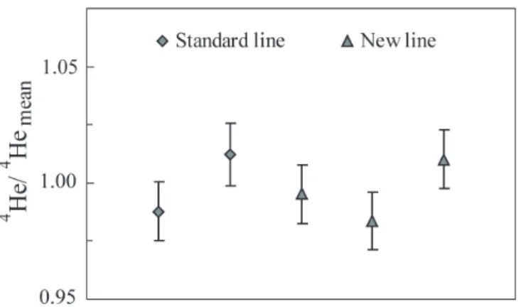
Sea water tests—To check the extraction efficiency of the
sys-tem, a batch of sea water re-equilibrated with air in the lab was sampled and analyzed both by the standard method we use for measuring helium isotopes in natural waters ( Jean-Baptiste et al. 1992), and with our new line (with the addition of degassed water but no heating). The results, presented in Fig. 4, show no discrepancy between the two sets of samples.
Artificial core tests—In theory, the efficiency of helium
recovery with the sediment extraction line should be the same as that of the standard line since our past results have always shown that the extraction efficiency for muddy water and pure water are identical. However, in order to check the helium extraction efficiency of the new line under the same experi-mental conditions as environexperi-mental samples, tests also were
carried out on an artificial core made from a water-sediment mixture equilibrated with the atmosphere. This sediment core was prepared as follows. First, the coastal marine sediments were washed and sieved (<0.2 mm). The sediment/water mix-ture then was allowed to rest for several days in a tank to remove much of the overlying water. The remaining water/ sediment mixture was stirred gently with a mechanical stirring device for 1 week to equilibrate with ambient air at 20 ± 0.5°C. Then, the mixture (water content = 67%) was placed in a spe-cially prepared 1.5 m long PVC tube (80 mm OD) kept verti-cal and closed at the bottom end with a plastic flange. The PVC tube had multiple axial slits, 1 mm wide / 50 mm long, made with a small circular saw. Each slit was covered with a small rectangular piece of filter paper fixed to the tube with adhesive tape. The entire tube was wrapped first with porous medical adhesive bandage, then with toilet paper and finally with elasticized bandage. After 3 weeks of slow percolation of the water out of the tube (at 20 ± 0.5°C), the height of the sediment/water column was reduced by approximately a third, corresponding to a final water content of 55%. At this stage, the flange could be re-opened and the core was sampled with copper tubes just like a natural sediment core.
Three samples were taken from the artificial core to check the efficiency of the extraction line. The measured 4He
concentra-tions are presented in Fig. 5. A slight neon excess was observed in all samples, likely due to air entrainment at the copper tube inner surface as it is jammed into the sediment core. Subsequent helium was assessed using Ne and He solubility given by Weiss
Fig. 5.(a) 4He concentrations in 3 samples of the artificial core analyzed
by our new method for extracting dissolved helium from sediment pore-waters. Triangles correspond to raw data. The dotted lines show the the-oretical solubility of helium in fresh water at 20°C (Weiss 1971) plus and minus 1%, which is a minimal uncertainty considering fluctuations of temperature and pressure during the preparation of the artificial core. Diamonds and squares are neon-corrected data. Diamonds correspond to a correction based on the neon solubility at 20°C given by Weiss (1971). (b) Fractionation between He and Ne during the sedimentation of the artificial core: the black square shows the solubility equilibrium at 20°C and the solid line represents an addition of air to this equilibrium; the dot-ted line fitting our measurements (triangles) is parallel to the “air addi-tion” line (1.5% shift). Solid squares in Fig. 5a correspond to a correction considering 1.5% neon super-saturation from equilibrium.
Fig. 4.Comparison of 4He concentrations in water samples extracted on
our standard line (Jean-Baptiste et al. 1992) used for natural waters (2 samples, diamond symbols) and the new extraction line for sediments (3 samples, triangle symbols). All data are normalized to the mean of the measurements obtained with our standard line. Error bars are one sigma uncertainty (overall uncertainty including counting statistics, blank repli-cation, etc., see Jean-Baptiste et al. 1992)
(1971) and subtracted from the raw measurements (diamonds in Fig. 5a). However, Fig. 5b shows that fractionation between He and Ne obviously occurred during the sedimentation of the arti-ficial core through filter paper: the black square shows the solu-bility equilibrium at 20°C and the solid line represents an addi-tion of air to this equilibrium; the dotted line which is the best linear fit through our measurements (triangles) is parallel to the “air addition” line but with a shift of about 1.5% toward higher neon values. We considered it more realistic to correct our data considering 1.5% neon super-saturation from equilibrium (solid squares in Fig. 5a). The neon-corrected 4He concentrations agree
with solubility data for fresh water at 20°C within uncertainties, thus indicating a full extraction.
Field core tests—Thanks to IFREMER and to the TOTAL oil
company, we had the opportunity to further test the validity
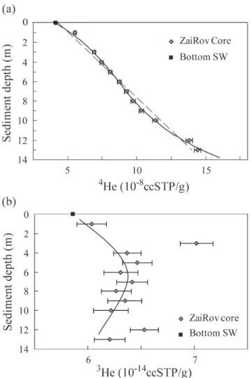
of the method on a 13-meter long core (KZR37, 5°50’S/ 9°45′W) drilled during the ZaiRov Leg 2 cruise in the Zaire deep-sea fan on the passive Congo-Angola margin (ZaiAngo project). Samples were taken in copper tubes at every meter. Eleven samples were analyzed (two were lost during extraction due to leak problems when re-opening the tube). The results are shown in Fig. 6.
Both a linear fit extrapolated to z = 0 or a polynomial fit show that the 4He concentrations are fully consistent with the 4He value for bottom water in the studied area (4.12 × 10⁻⁸cc/g),
taken as the average of oceanographic stations 205 and 213 (W. Roether, University of Bremen, South Atlantic helium data, WOCE section A13, at website http://whpo.ucsd.edu). This satisfactory agreement (both for the He concentration and for the 3He/4He isotopic ratio – see below) between bottom
waters and sediment pore-waters (extrapolated to z = 0) is the field confirmation of the overall efficiency of the sampling and extraction procedures. Notably, no artifacts related to temperature and pressure changes during core recovery can be noticed, although KZR37 is located at 3160-m water depth, much deeper than the lacustrine samples studied by Bren-nwald et al. (2003). As a matter of fact, even if small bubbles are formed during core handling, they are trapped in the sed-iment sampled in the copper tubes; we insist once more on the importance of sampling on board as soon as possible and of discarding the outer 5 cm of sediment.
A detailed interpretation of the helium profiles from the sediments of the Zaire deep-sea fan is beyond the scope of the present paper. However, the observation that the 4He
concen-tration in the sediment pore-waters increases almost linearly with depth suggests a predominantly diffusive transport of helium through the sedimentary column. The helium flux Φ (in mol per unit area of total sediment per unit of time) can be expressed by the Fick’s diffusion equation Φ = -nDeff× gradC where Deffis the apparent helium diffusion coefficient, n is the porosity (n∼ 0.8), and gradC is the measured vertical helium
pore-water concentration gradient. The apparent diffusion coefficient is always less than the diffusion coefficient D0in free water (D0∼ 5 × 10⁻⁵cm2/s Jähne et al. 1987) due to the
tor-tuosity of the bulk sediment. For surface sediments the ratio D0/Deffgenerally lies in the range 1.3–3 depending on the sed-iment properties, often characterized using formation factors (Manheim 1970; Manheim and Waterman 1974; Li and Gre-gory 1974). Taking gradC = 0.008 cm3STP/m4(see Fig. 6a) and
D0/Deff= 1.3 (corresponding to a high porosity sediment), the calculated flux, Φ = 2.5 × 10⁻¹¹ cm3STP/m2/s or 0.67 × 10⁹
atom/m2/s, compares favorably with the sum of the average
radiogenic 4He production in the oceanic crust and in the
local overlying sediment column estimated to 0.73 × 10⁹atom/
m2/s from Drescher et al. (1998), Rudnick and Gao (2003), and
Gay et al. (2006).
Figure 6 also displays the 3He concentration profile in the
sed-iment column (Fig. 6b). According to the radiocarbon dating of the base of the core, the mean accumulation rate is ∼ 30 cm/ka
Chaduteau et al. He isotopes in sediment pore-waters
Fig. 6.4He (a) and 3He (b) concentrations in the sediment pore-waters
of a ZaiRov core. The data have been neon-corrected to take possible air entrainment during sampling into account; this correction is generally less than 2%, with a maximum of 5.5%. In Fig. 6a, the dotted line corre-sponds to the linear fit of the pore-water data used to determine the mean vertical concentration gradient; the solid line (polynomial fit, power 3) smoothly fits the whole data set. Fig. 6b shows an arbitrary fit suggesting a peak in the 3He concentration at the Last Glacial Maximum.
(Dennielou, pers. comm.). The 0–3-m interval thus should correspond to the last 10 kyr or so, and the 6 m horizon to the Last Glacial Maximum. The consistently higher 3He
concen-trations in the sediment than in the present-day deep waters (5.86 × 10⁻¹⁴cm3STP/g at WOCE stations A13 205 and 213) is
coherent with the suggestion that the glacial Atlantic Ocean was less ventilated than the modern ocean due to a shallower and more sluggish North Atlantic deep water (NADW) circula-tion (Rutberg et al. 2000). The 3He concentration at z = 3-m
could be an outlier. However, it also could correspond to the Younger-Dryas event at ∼12 kyr BP when NADW formation is thought to have been substantially reduced for several thousand years (Bondevik et al. 2006). Clearly further work is needed if one wants to use 3He in sediment pore-waters as a
paleoceanographic tool, but these preliminary results are quite encouraging.
Discussion
Our new experimental method yields satisfactory determi-nations of 4He and 3He concentrations in sediment
pore-waters without releasing 4He from sediment minerals. The
sampling technique is non-destructive for the core (no squeez-ing) and is applicable to any marine or lake sediment core. This sampling approach can be implemented easily on any oceanographic coring cruise, so it could help to broaden the geographic distribution of available data.
Beyond the promising range of applications in paleoceano-graphic studies (see introduction), helium isotope
geochem-istry of sediment pore-water is of particular interest for a num-ber of processes pertaining to geophysics and geochemistry (Mamyrin and Tolstikhin 1984). For instance, at ODP drilling sites, our technique makes it possible to get high resolution profiles down to the oceanic crust, with exciting implications for noble gas geochemistry. Specifically, on sedimented flanks of active spreading ridges where thermally driven hydrother-mal circulation and associated geochemical fluxes are still poorly known, measurements of helium isotopes in pore-waters could improve our current understanding of diffusive and advective fluxes of heat and chemical species greatly (Mottl and Wheat, 1994; Wheat et al., 2000). On a local scale, tracing fluid advection and gaining insights into residence times and sources bring information about the geological set-ting and the geotectonic features of a region (Sano et al. 1992). On a global scale, the models of terrestrial helium degassing also could be improved (Sano 1986; Torgersen 1989). This list of applications is not exhaustive but shows the potential of this geochemistry tool.
Comments and recommendations
From our experience, sampling could be facilitated by developing a motorized sampling device to push in the copper tube. With compact sediments considerable force often is needed to drive in the tube, and this can be difficult to accom-plish manually.
The extraction step itself is not very time consuming (30 min). But if we include the time required to clean up and pump the line between each sample, our prototype allows us to deal only with two samples a day. Therefore, in order to increase the throughput and study longer cores, we plan to build addi-tional lines that can be operated in parallel.
This method was specifically designed to extract helium from sediment pore-waters. However, the non-destructive sampling technique we describe is also fully adaptable for any dissolved volatile species.
References
Adkins, J. F., K. McIntyre, and D. P. Schrag. 2002. The salinity, temperature and δ18O of the glacial deep ocean. Science
298:1769–1773.
Barnes, R. O. 1973. An in situ interstitial water sampler for use in unconsolidated sediments. Deep-Sea Res. 20: 1125–1128.
——— 1988. ODP in-situ fluid sampling and measurement: a new wireline tool. In A. Mascle and J. Moore (Eds.), Proc.
ODP, Init. Reports (part A) 110:55–63.
Bondevik, S., J. Mangerud, H. H. Birks, S. Gulliksen, and P. Reimer. 2006. Changes in North Atlantic radiocarbon reservoir ages during the Allerod and Younger dryas. Sci-ence 312:1514–1517.
Brennwald, M. S., M. Hofer, F. Peeters, W. Aeschbach-Hertig, K. Strassmann, R. Kipfer, and D. M. Imboden. 2003. Analysis of dissolved noble gases in the porewater of lacustrine sed-iments. Limnol. Oceanogr.: Methods 1:51–62.
Broecker, W. 1973. Interstitial water studies, leg 15, introduc-tion and summary. Init. Rep. DSDP Leg 15:1069–1073 [doi:10.2973/dsdp.proc.15.139.1973].
Clarke, W. B., R. M. Horowitz, and W. S. Broecker. 1973. Inter-stitial water studies, leg 15, inert gases. Init. Rep. DSDP 20: 777–781[doi:10.2973/dsdp.proc.20.206.1973]
Dyck, W., and F. G. Da Silva. 1981. The use of ping-pong balls and latex tubing for sampling the helium content of lake sediments. J. Geochem. Exp. 14:41–48.
Drescher, J., T. Kirsten, and K. Schäfer. 1998. The rare gas inventory of the continental crust, recovered by the KTB Continental Deep Drilling Project. Earth Planet. Sci. Lett. 154:247–263.
Dutay, J. C., and others. 2004. Evaluation of OCPMIP-2 ocean models’ deep circulation with mantle helium-3. J. Mar. Sys-tems 48:15–36.
Farley, K. A., E. Maier-Reimer, P. Schlosser, and W. S. Broecker. 1995. Constraints on mantle 3He fluxes and deep-sea
circu-lation from an oceanic general circucircu-lation model. J. Geo-phys. Res. 100(B3):3829–3840.
Gay, A., M. Lopez, H. Ondreas, J. L. Charlou, G. Sermondadaz, and P. Cochonnat. 2006. Seafloor facies related to upward methane flux within a Giant Pockmark of the lower Congo basin. Marine Geol. 226:81–95.
the diffusion coefficients of sparingly soluble gases in water. J. Geophys. Res. 92(C10):10,767–10,776.
Jean-Baptiste, P., F. Mantisi, A. Dapoigny, and M. Stievenard. 1992. Design and performance of a mass spectrometric facil-ity for measuring helium isotopes in natural waters and for low level tritium determination by the 3He ingrowth method.
Int. J. Radiat. Appl. Instrum. (Part A) 43(7):881–891.
Jenkins, W. J., and W. B. Clarke. 1976. The distribution of 3He
in the western Atlantic Ocean. Deep-Sea Res. 23:481–494. Kipfer, R., W. Aeschbach-Hertig, F. Peteers, and M. Stute. 2002.
Noble gases in lakes and groundwaters. In Noble gases in
geochemistry and cosmochemistry, D. Porcelli, C. J. Ballen-tine, and R. Wieler (Eds.) Rev. Min. Geochem. 47:615–700. Li, Y. H., and S. Gregory, 1974. Diffusion of ions in sea water and deep sea sediments. Geochim. Cosmochim. Acta 37: 703–714.
Mamyrin, B. A., and I. N. Tolstikhin, 1984. Helium isotopes in nature. Elsevier.
Manheim, F. T. 1970. The diffusion of ions in unconsolidated sediments. Earth Planet. Sci. Lett. 9:307–309.
———, and L.S. Waterman. 1974. Diffusimetry (diffusion con-stant estimation) on sediment cores by resistivity probe. Init. Reports of the DSDP 22:663–670 [doi:10.2973/dsdp. proc.22.132.1974].
Mottl, M. J., and C. G. Wheat. 1994. Hydrothermal circulation through mid-ocean ridge flanks: Fluxes of heat and magne-sium. Geochim. Cosmochim. Acta 58:2225–2237.
Rutberg, R. L., S. H. Hemming, and S. L. Goldstein. 2000. Reduced North Atlantic Deep Water flux to the glacial Southern Ocean inferred from neodymium isotope ratios. Nature 405:935–938.
Rudnick, R. L., and S. Gao. 2003. Composition of the conti-nental crust. In Rudnick, R. (Ed.), Treatise on Geochemistry
3:1–64.
Sano, Y. 1986. Helium flux from the solid earth. Geochem. J. 21:227–232.
———, M. Sakamoto, J. Ishibashi, H. Wakita, and R. Matsumoto.
1992. Helium isotope ratios of pore gases in deep-sea sedi-ments, leg 128. In K. A. Pisciotto, J. C. Ingle, M. T. von
Brey-mann, and J. Barron (Eds.), Proc. ODP, Scient. Res. 127/128: 747–751.
Schlosser, P., and G. Winckler. 2002. Noble gases in ocean waters and sediments. In Noble gases in geochemistry and
cosmochemistry, D. Porcelli, C.J. Ballentine, and R. Wieler (Eds.) Rev. Min. Geochem. 47:701–730.
Schrag, D. P., G. Hampt, and D. W. Murray. 1996. Pore fluid constraints on the temperature and oxygen isotopic com-position of the glacial ocean. Science 272:1930–1932. Stephenson, M., W. J. Schwartz, T. W. Melnyk, and M. F.
Moty-cka. 1994. Measurement of advective water velocity in lake sediment using natural helium gradients. J. Hydrol. 154: 63–84.
Torgersen, T. 1989. Terrestrial helium degassing fluxes and the atmospheric helium budget: Implications with respect to the degassing processes of continental crust. Chem. Geol. 79:1–14.
Torres, M. E., R. Bayer, G. Winckler, A. Suckow, and K. Froehlich. 1995. Elemental and isotopic abundance of noble gases in formation fluids recovered in situ from the Chile Triple Junction. In S. D. Lewis, J. H. Behrmann, R. J. Musgrave,
and S. C. Cande (Eds.), Proc. ODP, Scient. Res. 141: 321–329.
Weiss, R.F. 1968. Piggyback sampler for dissolved gas studies on sealed water samples. Deep-Sea Res. 15:695–699. ——— 1971. Solubility of helium and neon in water and
sea-water. J. Chem. Eng. Data. 16:235–241.
Wheat, C. G., H. Elderfield, M. J. Mottl, and C. Monnin. 2000. Chemical composition of basement fluids within an oceanic ridge flank : Implication for along-strike and across-strike hydrothermal circulation. J. Geophys. Res. 105:13,437– 13,447.
Submitted 9 October 2006 Revised 27 July 2007 Accepted 10 August 2007