Publisher’s version / Version de l'éditeur:
Journal of the Acoustical Society of America, 110, December 6, pp. 3086-3096,
2001-12-01
READ THESE TERMS AND CONDITIONS CAREFULLY BEFORE USING THIS WEBSITE. https://nrc-publications.canada.ca/eng/copyright
Vous avez des questions? Nous pouvons vous aider. Pour communiquer directement avec un auteur, consultez la
première page de la revue dans laquelle son article a été publié afin de trouver ses coordonnées. Si vous n’arrivez pas à les repérer, communiquez avec nous à [email protected].
Questions? Contact the NRC Publications Archive team at
[email protected]. If you wish to email the authors directly, please see the first page of the publication for their contact information.
NRC Publications Archive
Archives des publications du CNRC
This publication could be one of several versions: author’s original, accepted manuscript or the publisher’s version. / La version de cette publication peut être l’une des suivantes : la version prépublication de l’auteur, la version acceptée du manuscrit ou la version de l’éditeur.
For the publisher’s version, please access the DOI link below./ Pour consulter la version de l’éditeur, utilisez le lien DOI ci-dessous.
https://doi.org/10.1121/1.1416200#
Access and use of this website and the material on it are subject to the Terms and Conditions set forth at
On the sound insulation of wood stud exterior walls
Bradley, J. S.; Birta, J. A.
https://publications-cnrc.canada.ca/fra/droits
L’accès à ce site Web et l’utilisation de son contenu sont assujettis aux conditions présentées dans le site
LISEZ CES CONDITIONS ATTENTIVEMENT AVANT D’UTILISER CE SITE WEB.
NRC Publications Record / Notice d'Archives des publications de CNRC:
https://nrc-publications.canada.ca/eng/view/object/?id=361fd5c8-82ff-4c50-ba7b-d9f6739fef25 https://publications-cnrc.canada.ca/fra/voir/objet/?id=361fd5c8-82ff-4c50-ba7b-d9f6739fef25On the sound insulation of wood stud exterior walls
Bradley, J.S.; Birta, J.A.
NRCC-44764
A version of this document is published in / Une version de ce document se trouve dan
Journal of the Acoustical Society of America, v. 110, no. 6, Dec. 2001, pp. 3086-3096
On the sound insulation of wood stud exterior walls
J. S. Bradleya)and J. A. Birta
Institute for Research in Construction, National Research Council, Montreal Road, Ottawa K1A 0R6, Canada
~Received 6 April 2001; revised 15 August 2001; accepted 6 September 2001!
This article reports the results of a series of measurements of the sound transmission loss of exterior wood stud walls. The measurements were made using standard laboratory procedures in which the walls were built between two reverberation chambers. The outdoor–indoor transmission class is used to rate the relative effectiveness of the various constructions. The measurement results are used to illustrate the influence of key parameters of the constructions on measured sound transmission loss values and to give guidance for future designs. The overall sound insulation of these wood stud walls, to typical outdoor noises, is shown to be limited by two types of low-frequency resonances. An understanding of these low-frequency limitations can most effectively lead to superior sound insulation in similar wood stud walls. © 2001 Acoustical Society of America.
@DOI: 10.1121/1.1416200#
PACS numbers: 43.55.Rg, 43.55.Nd @JDQ#
I. INTRODUCTION
In North America, homes are commonly built with wood stud exterior walls, which are often required to be effective barriers to outdoor noises such as those from aircraft and road traffic. Improved sound insulation of homes is fre-quently the only practical means of reducing the impact of aircraft and other outdoor noises. However, the scarcity of published measurements concerning the sound transmission loss of modern exterior wall constructions has made it diffi-cult to design cost-effective solutions to sound insulation problems. Modern energy conservation requirements have led to more air tight and thicker walls with more thermal insulation than in older constructions. Existing data could only be found for older styles of construction and almost always exclude the important lower frequency bands.1
This article presents analyses of the measurements of the sound transmission loss of a series of exterior wood stud walls. The walls are representative of contemporary con-structions used in climates where significant thermal insula-tion is required. The measurements included important low-frequency bands to make it possible to correctly characterize the overall effectiveness of the walls when exposed to typical outdoor sounds.
This work is part of a larger project to measure the sound transmission loss of various exterior building facade components and to develop a computer-based procedure for the design of the sound insulation of buildings exposed to aircraft noise. The sound transmission loss of over 100 con-structions has been measured in standard laboratory tests.2 These have included various roof constructions and windows as well as 41 wood stud walls. A report with the complete data has been published.3The current article focuses on the influence of key construction parameters, of the 41 wood stud walls, on the resulting sound transmission loss values.
The laboratory measurements were obtained for ideal conditions in which sound is incident on the test walls more
or less equally from all directions. When an aircraft flies by a building, the sound is incident from a more limited range of angles. Because of the directional properties of aircraft noise radiation and the varying position of the aircraft, the incident sound energy also varies with angle of incidence to the exposed building facade.4As a result it is expected that sound insulation measured in the field with aircraft as the noise source will differ from measurements of the same con-structions in the laboratory. However, it was felt that the sound insulation of building facade elements could be most accurately characterized in standard laboratory tests and that corrections could later be derived to better approximate the differences that occur in the field. These corrections will later be obtained from work that includes measurements of the sound insulation of a simple test structure and actual houses exposed to real aircraft flyovers. The current article considers only the laboratory measurements.
The new laboratory data are used in this article to illus-trate the effects of varied: surface mass, stud size, stud spac-ing, structural breaks, and cavity thermal insulation on the sound transmission loss of exterior walls. The influence of these parameters is shown directly for a number of construc-tions and the trends from these results provide more general guidance for achieving improved sound insulation in other wood stud walls. The new results also add to our understand-ing of the importance of low-frequency resonances that typi-cally limit the overall sound insulation of exterior wood stud walls.
In addition to the sound transmission loss values mea-sured as a function of 13 octave band frequency, the overall
sound insulation of each wall was rated in terms of the outdoor–indoor transmission class ~OITC!.5 The OITC rat-ing provides a simple means of rank orderrat-ing the effective-ness of the various walls and is a measure of the overall A-weighted level reduction for the wall using a standard source spectrum said to be representative of typical outdoor noises. It is not appropriate to use the STC ~sound
transmis-a!
Electronic mail: [email protected]
sion class6! for exterior walls exposed to sounds with signifi-cant low-frequency sound energy.
II. MEASUREMENT AND CONSTRUCTION DETAILS
The sound transmission loss tests were carried out fol-lowing the ASTM E90 procedure2 according to which the walls are constructed between two reverberation chambers. For the current tests the two reverberation chambers had vol-umes of 250 and 138 m3. Walls were constructed in a mas-sive test frame that was positioned between the two cham-bers and in which walls were constructed measuring 2.44 m high ~8 ft.! by 3.66 m long ~12 ft.! The test frame rolls into place on heavy steel tracks and is sealed into place between the two chambers with pneumatic seals as well as with foam seals and metal adhesive tape. Both chambers contain diffus-ing panels to increase the randomization of sound reflections. The actual test procedure exceeded the requirements of the ASTM E90 standard in several ways. Until recently the standard has required measurements to be made only in the
1
3octave bands from 125 to 4000 Hz, but in this work
mea-surements were reported for the 13 octave bands from 50 to
5000 Hz. The additional lower frequency measurements are particularly important because typical outdoor sound sources such as aircraft noise contain significant low-frequency sound energy. Although there are larger uncertainties associ-ated with the lower frequency measurements, including these lower frequency measurements led to an improved under-standing of the important low-frequency transmission loss of wood stud walls. In the laboratory measurements, sound lev-els were measured at nine independent locations in the source and the receiving reverberation chambers. Similarly, reverberation times were measured from the ensemble aver-age of ten decays at the same nine independent microphone positions in the receiving chamber. The tests were repeated for both directions of propagation through the test partitions and the results presented here are the averages of the two tests.
Most walls were constructed as variations of a base wall. The base wall consisted of 38-mm by 140-mm wood studs with a 406-mm stud spacing. These have traditionally been referred to as 2 by 6 studs but here are described as 140-mm studs. The base wall included vinyl siding directly attached to 11-mm oriented strand board ~OSB! sheathing as the outer surface and 13-mm gypsum board as the internal surface. Both the OSB and the gypsum board were screwed to the wood studs. The details of the screw spacings were those recommended by the National Building Code of Canada. The stud cavity was filled with glass fiber thermal insulation. Ex-cept for specific additions and variations, all walls were con-structed of these same materials.
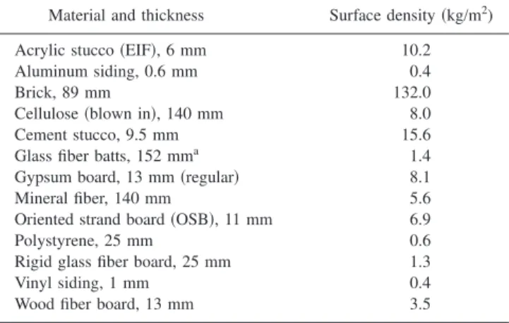
Table I includes the surface densities of the various ma-terials. Except where otherwise noted, all of the walls had vinyl siding on the exterior face and included a polyethylene vapor barrier immediately under the interior gypsum board. Only 13-mm-thick regular gypsum board and 11-mm-thick OSB sheathing were used.
To correctly interpret the significance of small differ-ences between test results, it is important to known how accurately transmission loss measurements can be repeated
on rebuilding the particular construction. Repeated measure-ments of the base wall construction give some indication of the expected repeatability of these measurements in terms of individual 1
3-octave band results as well as in terms of OITC
values. When the test frame was removed and repositioned with exactly the same construction, 1
3-octave band
transmis-sion loss values repeated within less than 60.2 dB at all frequencies . Rebuilding the wall led to small differences that fluctuate with frequency. When rebuilding with the same ma-terials, 1
3-octave band transmission loss values changed by up
to about 1 dB with a rms ~root mean square! difference over all frequencies of 0.5 dB. When the wall was rebuilt with new materials the maximum change was about 2 dB and the rms difference 1 dB. In terms of OITC values, rebuilding with the same material led to a change of 0.3 and rebuilding with new materials led to a change of 0.7. Thus one cannot confidently identify the cause of small changes of less than about 0.7 in OITC values. In spite of this uncertainty, smaller changes are probably meaningful when only parts of the con-struction have been changed such as the addition of a second layer of gypsum board. Some changes are also more likely to be meaningful when they are observed to occur consistently over a range of frequencies.
III. BASIC PRINCIPLES
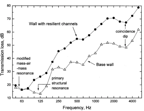
Many of the walls were variations from a base wall, described in Sec. II, and exhibit a number of common char-acteristics. Figure 1 illustrates the measured sound transmis-sion loss measurements for the base wall and also for a sec-ond wall that includes a double layer of 13-mm gypsum board attached via resilient channels. That is, the single layer of gypsum board on the base wall was replaced with a double layer attached via screws to the resilient channels. These two walls illustrate the basic phenomena that influence the sound insulation of the various wood stud walls. The results quite obviously show the advantage of using resilient channels to create a structural break between the two outer surfaces. The wall with resilient channels has much superior sound transmission loss at higher frequencies. However, at very low frequencies, where the sound transmission loss is lowest, both walls have quite similar sound transmission loss values.
TABLE I. Surface densities of the various materials used in these test walls. Material and thickness Surface density ~kg/m2)
Acrylic stucco ~EIF!, 6 mm 10.2
Aluminum siding, 0.6 mm 0.4
Brick, 89 mm 132.0
Cellulose ~blown in!, 140 mm 8.0
Cement stucco, 9.5 mm 15.6
Glass fiber batts, 152 mma 1.4
Gypsum board, 13 mm ~regular! 8.1
Mineral fiber, 140 mm 5.6
Oriented strand board ~OSB!, 11 mm 6.9
Polystyrene, 25 mm 0.6
Rigid glass fiber board, 25 mm 1.3
Vinyl siding, 1 mm 0.4
Wood fiber board, 13 mm 3.5
a
The sound transmission loss curves in Fig. 1 include several dips that limit the overall sound insulation. Both curves include a dip at about 2.5 to 3.1 kHz. This is the well-known coincidence dip of the gypsum board and OSB panels that occurs when there is a coincidence between the velocity of bending waves in the panels and the incident sound.7
The lower frequency dips in the Fig. 1 results and later results will be explained mostly in terms of the results of work by Lin and Garrelick.8Their work does not seem to be widely known but does appear to explain the most important low-frequency features of sound transmission through these wood stud walls. At low frequencies the base wall includes a dip at about 125 Hz. This has not been clearly evident in many previous tests because the ASTM standard2 did not previously require measurements below 125 Hz. The work of Lin and Garrelick would indicate that this is the primary structural resonance of the ribbed panel system formed by the stud wall and the rigidly attached surface layers. It is very important because it reduces the sound transmission loss of the wall to its lowest value for any frequency and hence limits the overall performance of the wall.
Lin and Garrelick also showed that when the two layers are not rigidly connected, the system is changed and no longer has a primary structural resonance. Thus, when one of the surface layers is mounted using resilient channels, this primary structural resonance no longer occurs. The ribbed panel system is effectively broken up and the two surface layers can vibrate more or less independently. However, for this case the two surface layers are still coupled by the stiff-ness of the air cavity and a mass–air–mass resonance occurs. The frequency of this resonance is determined by the com-bination of the masses of the surface layers and the stiffness of the contained air and for these walls is considerably lower in frequency than the primary structural resonance. A recent paper9 has shown that the frequency of this resonance is modified by the addition of the stiffness of the resilient
chan-nels. This modified mass–air–mass resonance limits the low-frequency transmission loss of the wall with resilient chan-nels. Again because the transmission loss of the wall is least in this frequency region, the resonance limits the overall per-formance of the wall.
Although the coincidence dip affects the sound transmis-sion loss of the walls, it occurs at a frequency where the sound transmission loss is quite high. Thus, the coincidence dip is often of less practical importance because the trans-mitted sound energy is much greater at lower frequencies. However, the primary structural resonance seen in the base wall and the modified mass–air–mass resonance in the wall with resilient channels significantly limit the overall sound insulation of many walls and are therefore significant im-pediments to achieving improved sound insulation against typical outdoor noises.
The overall performance of the walls in this article are compared using the outdoor–indoor transmission class ~OITC!.5 This is essentially the A-weighted level reduction with a standard source spectrum. Figure 2 compares this standard spectrum to an average spectrum for modern com-mercial jet aircraft from measurements made as part of this project. The OTIC source spectrum is seen to have relatively higher levels at very low and very high frequencies. Because the sound transmission loss of walls is most limited at lower frequencies, these increased source levels at lower frequen-cies would tend to exaggerate the expected indoor sound levels at lower frequencies relative to those expected for a typical aircraft noise spectrum.
Figure 3 illustrates the expected A-weighted indoor lev-els for the base wall and the two source spectra from Fig. 2. ~Both calculations were made assuming a receiving room volume of 57 m3, an exposed wall area of 10.7 m2, and a receiving room reverberation time of 0.4 s, corresponding to an average living room.10! These results more clearly dem-onstrate the importance of the primary structural resonance at 125 Hz, which dominates the indoor A-weighted levels. The FIG. 1. Illustration of the basic phe-nomena influencing sound transmis-sion loss for ~a! the base wall, and ~b! a wall with two layers of gypsum board on resilient channels.
OITC source spectrum does exaggerate this effect a little. One could contemplate using different source spectra for dif-ferent types of outdoor noise sources. Using an aircraft noise spectrum rather than the OITC source spectrum led to re-duced overall level ratings of about 3 dB. However, the dif-ferent source spectrum shape does not have much effect on the rank ordering of the constructions and using other non-standard source spectra would detract from the beneficial generality of OITC rating.
Subsequent results will be presented as both conven-tional sound transmission loss versus frequency plots and also in terms of the expected indoor sound levels as illus-trated in Fig. 3. Indoor levels were calculated using the same
aircraft noise spectrum as in Fig. 2 and for the same average living room previously described. This form of plot directly shows the frequencies at which the highest levels occur and clearly indicates where the overall sound insulation is most critically limited.
IV. EFFECTS OF ADDING MASS
Figure 4 illustrates examples of adding more massive outer surface to a wood stud wall. The sound transmission loss is said to be mass controlled at frequencies above low-frequency resonances and below the coincidence dip region. In this region increased mass increases the measured sound FIG. 2. Comparison of the standard OITC source spectrum with the source spectrum for modern commercial jet aircraft.
FIG. 3. Comparison of indoor A-weighted sound levels with the base wall and either the OITC source spec-trum or the aircraft source specspec-trum from Fig. 2.
transmission loss. The OITC value for the base wall is 25. This is increased to 27 when vinyl siding is replaced by acrylic ~EIF! stucco and to 29 when a heavier cement stucco exterior is used. However, adding brick as the outer layer has a much greater effect on the OITC rating which is increased to 40.
The effect of the added mass on the resulting OITC ratings approximately follows a 10 log$M / M0% relationship
~where M is the total surface mass with additions and M0 is
the original total surface mass of the base wall!. The ex-pected increments in OITC ratings according to this relation-ship for various materials added to the base wall are given in Table II along with the measured OITC ratings.
The measured improvements in OITC ratings relative to the base wall case are generally very close to the 10 log$M / M0% relationship. The improvement due to the
brick is greater than might be expected because in addition to the much larger surface density ~see Table I!, there is
effec-tively a structural break because the bricks are only con-nected to the rest of the wall via occasional metal ties.
Adding the cement stucco, which adhered directly on the exterior sheathing, is seen to modify the shape of the trans-mission loss curve in Fig. 4 in the region of the coincidence dip. Although this may seem important on the transmission loss versus frequency plot, the indoor sound level plot indi-cates that these differences are of little practical importance because sound levels at these frequencies are more than 30 dB below the low-frequency maximum A-weighted levels. Replacing the exterior OSB sheathing with wood fiber board only had a small effect ~not shown!. Although the wood fiber board has a lower surface density ~see Table I!, the sound transmission loss increased by a few dB at higher frequen-cies when wood fiber board was used as the exterior sheath-ing. The overall OITC rating with wood fiber board was the same value of 25 as for the base case. When the vinyl siding was attached over external thermal insulation or over an air space, there were changes to the measured transmission loss at higher frequencies but the OITC rating did not change ~not shown!.
In all of the results in Fig. 4, the transmission loss is always least at the frequency of the primary structural reso-nance. That is, the overall indoor sound levels are always greatest at about 125 Hz and this limits the overall perfor-mance of the wall. This is also true even when brick is added to the wall except that this resonance frequency appears to shift to a slightly lower frequency. For these walls, further significant reductions of indoor sound levels would require modification of this resonance. There are other smaller peaks in the indoor sound levels of the base wall at 315 and 630 Hz. Their cause is not known but the peak in the 630-Hz band seems to vary with the surface treatment in Fig. 5. They are more than 10 dB below the 125-Hz peak in indoor levels and hence are of less practical importance.
V. EFFECTS OF STUD SIZE AND SPACING
Both stud size and stud spacing are found to influence the sound transmission loss of walls and the effects are not independent but interact such that the effect of stud size is more significant for larger stud spacings. Figure 5 illustrates results for four combinations of stud size and spacing. If the stud size of the base wall configuration ~140-mm studs at 406-mm spacing! is decreased to 89-mm studs with the same spacing, the results in Fig. 5 indicate a reduction of the OITC rating from 25 to 24. However, increasing the stud spacing from 406 to 610 mm results in a 3-point improvement in OITC for the 89-mm studs and a 6-point improvement for the 140-mm studs. These improvements are largely the result of changes to the frequency of the primary structural reso-nance. Increasing the stud size ~open symbols! lowers the frequency of this resonance and increasing the stud spacing ~square symbols! leads to an even larger reduction in the resonance frequency. Because the maximum indoor sound levels occur at this resonance frequency, these modifications can significantly reduce indoor sound levels.
The important effects of stud spacing are further illus-trated in Fig. 6 for 89-mm stud walls. Varying the stud spacing from 305 mm to 406 mm and to 610 mm systemati-FIG. 4. Effects of adding mass to the base wall by adding heavier exterior
surface layers. ~See Table I for surface densities.!
TABLE II. Calculated expected increases due to increased mass and mea-sured OITC ratings.
Added material 10 log$M / M0% Measured OITC
Base wall ••• 25
Second layer gypsum board 1.9 27
Acrylic ~EIF! stucco 2.2 27
Cement stucco 3.1 29
Alulminum siding 0 25
Brick 9.9 40
cally reduces the resonance dip from 200 Hz to 125 Hz and to 80 Hz. These changes correspond to OITC ratings of 23, 24, and 27. The results of Figs. 5 and 6 clearly indicate the importance of the stud size and spacing on the overall per-formance of the wall. Variation of these parameters led to variations in OITC values from 23 to 31. It is thus possible to achieve substantial improvements in the sound transmission loss of wood stud walls by appropriate choice of stud size and spacing.
The measured shifts in the low-frequency resonance with varied stud spacings are particularly convincing evi-dence that this is the primary structural resonance that Lin and Garrelick predict. A simple mass–air–mass reso-nance would not be expected to shift in frequency with stud spacing.
VI. EFFECTS OF STRUCTURAL BREAKS
Including structural breaks in the construction of a wall improves the sound insulation by preventing the direct trans-mission of energy from one surface to the other. It also has the benefit of eliminating the primary structural resonance for the ribbed panel system formed by a stud wall without a structural break. Eliminating this resonance often removes the weakest component of the sound insulation and hence improves the overall performance of the wall. In these mea-surements, structural breaks were introduced either by mounting the gypsum board on resilient channels or by using staggered stud systems where two sets of 89-mm studs are
built with a 140-mm plate and header so that that each sur-face of the wall is attached to a separate set of studs.
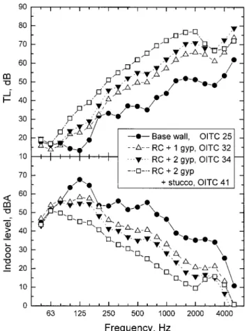
Figure 7 illustrates measured sound transmission loss values for three examples of walls that include resilient chan-nels as well as results for the base wall configuration. As indicated previously in Fig. 1, adding resilient channels eliminates the primary structural resonance at about 125 Hz and introduces a modified mass–air–mass resonance in the 63-Hz 13-octave band. At almost all frequencies above this,
the addition of resilient channels leads to significant im-provements in the measured sound transmission loss. For the case of a single layer of 13-mm gypsum board mounted on resilient channels, the OITC rating increased to 32 from the value of 25 for the base wall. For the wall with a double layer of gypsum board on resilient channels, the OITC rating increased to 34. When cement stucco was added to this last wall, the OITC was further increased to 41. This is slightly larger than the OTIC rating of 40 for the wall with a brick exterior and indicates that the combination of a structural break and adequate mass can provide superior sound insula-tion. A wall constructed with wood fiber board as the exterior sheathing and with a double layer of gypsum board on resil-ient channels on the interior surface had sound transmission loss characteristics very similar to the comparable wall con-structed with OSB as the exterior sheathing.
The modified mass–air–mass resonances occur in or near the 63-Hz 13-octave band as expected. The added
stiff-ness of the resilient channel influences the frequency of this resonance,9 but there is a small trend for the transmission FIG. 6. Effects of varying stud spacing for 89-mm wood stud exterior walls. FIG. 5. The effects of varying stud size and stud spacing for wood stud
loss versus frequency curve to indicate a small shift to lower frequencies with added surface mass.
Figure 8 shows the measured sound transmission loss values for four constructions based on staggered stud sys-tems. In all cases the walls were constructed with two sets of 89-mm wood studs on a 140-mm plate and with a stud spac-ing of 610 mm. The four results in Fig. 8 show the effect of different surface treatments. The first set of results with a single layer of gypsum board on the inner surface and a single layer of OSB on the exterior surface had an OITC rating of 33 which is 8 points better than the base wall. The staggered stud construction effectively breaks the structural path between the two surface layers and eliminates the pri-mary structural resonance found in the base wall. For the staggered stud walls the low-frequency sound transmission loss is limited by a mass–air–mass resonance which, as ex-pected, seems to shift lower in frequency as more mass is added to the surface layers of the wall. Thus, doubling the OSB increases the OITC rating to 37 and doubling the gyp-sum board increases it to 39 because the gypgyp-sum board is heavier than the OSB. Doubling both external layers is seen to further increase the low-frequency sound insulation and leads to an OITC rating of 43.
The staggered stud constructions in Fig. 8 are more ef-fective than the constructions with resilient channels in Fig. 7 because they have improved low-frequency performance. Although the surface masses are similar, the staggered stud walls have lower stiffness because they do not include the
added stiffness of resilient channels. This leads to mass–air– mass resonances that are lower in frequency for the stag-gered stud walls and hence to improved low-frequency trans-mission loss.
These tests were repeated for similar staggered stud wall constructions but with a 406-mm stud spacing. The measured transmission loss values were very similar with only very small differences. This included the same unexpectedly small increase in transmission loss with increased surface mass at mid and higher frequencies that occurred for both stud spac-ings. The OITC ratings of the walls were identical to those of Fig. 8. When a wood stud wall includes a structural break, as in these staggered stud walls, the stud spacing is not impor-tant. The stud spacing is only important in walls without structural breaks because in these walls it influences the fre-quency of the primary structural resonance. Again, with the structural break and adequate mass, superior sound insula-tion can be achieved.
When resilient channels are added to a staggered stud wall system, further improvements are obtained in the mea-sured sound transmission loss values indicating that the structural break created by the staggered studs in imperfect. Figure 9 compares measured sound transmission loss values for staggered stud walls including resilient channels ~solid symbols! with similar walls without resilient channels ~open symbols!. For a staggered stud wall with a single layer of gypsum board and a double layer of OSB, adding resilient channels significantly increases the mid- and high-frequency FIG. 7. Effects of various surface layers mounted on resilient channels
~RC!. ~1 gyp51 layer of 13-mm gypsum board; stucco is cement stucco attached to the exterior sheathing.!
FIG. 8. Effects of various surface layers on a staggered wood stud wall. ~1 gyp51 layer of 13-mm gypsum board; 2 OSB52 layers of 11-mm oriented strand board.!
sound transmission loss. However, the OITC rating only in-creases from 37 to 38. Similarly, adding resilient channels to a staggered stud wall with double layers of both gypsum board and OSB only increased the OITC rating from 43 to 44.
In both examples in Fig. 9, adding resilient channels leads to large improvements in sound transmission loss above 250 Hz. It is likely that these results indicate an effec-tive flanking path at higher frequencies via the plate and header that connect the two stud systems in the staggered stud walls without resilient channels. These results may give insight into the limitations of staggered stud wall systems but they are of less practical importance for typical outdoor noises because the overall sound insulation is most severely limited at the low frequencies. The staggered stud walls can provide OITC ratings of up to 44, which is 4 points greater than measured for the brick wall and hence can be an effec-tive means of obtaining superior sound insulation.
VII. EFFECTS OF CAVITY INSULATION
The effects of different types of cavity insulation were measured for walls that included a double layer of 13-mm gypsum board mounted on resilient channels. The effects of different cavity insulations were expected to be more readily detectable ~larger! for this wall construction. Three types of cavity insulation were evaluated. These were glass fiber batts, mineral fiber batts, and dry blown in cellulose fiber.
Figure 10 compares the measured sound transmission loss values and shows that the different materials led to small changes in transmission loss and only at higher frequencies. Because the type of insulation did not greatly influence the important low-frequency sound transmission loss, the overall ratings of the walls did not change much. The OITC rating of 34 for the glass fiber insulation increased to 35 for the cel-lulose fiber and to 36 for the mineral fiber. These OITC increases were partially due to the rounding up to the nearest integer value that is part of the OITC calculation. ~If the OITC values were calculated to one decimal place, the in-creases would be 0.7 and 1.7.!
These differences in OITC values are in one case the same as, and in the other case only a little larger than, the rebuild repeatability difference. One should therefore be cau-tious in attributing significance to these small differences and remember that other parameters have much larger effects on the overall sound insulation. It is also quite likely that the differences due to different cavity insulation material would be different for other wall constructions and much smaller for walls without a structural break.
VIII. DESIGN CHOICES
The various walls that were tested had OITC ratings varying from the OITC of 25 for the base wall to values in excess of the OITC of 40 obtained for a wall with a brick surface. All of the construction parameters that were consid-ered influenced the overall sound insulation rating. The de-FIG. 9. Comparison of staggered wood stud walls with ~solid symbols! and
without ~open symbols! added resilient channels ~RC!. ~2 gyp52 layers of 13-mm gypsum board; 2 OSB52 layers of oriented strand board.!
FIG. 10. Effects of different thermal insulations completely filling the stud cavity in walls with a double layer of gypsum board on resilient channels.
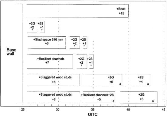
signer needs an overview of the various results to help in selecting an appropriate construction with adequate sound insulation. The summary chart shown in Fig. 11 has been constructed to give an overview of the importance of each parameter. Although it is reasonably complete it does not include all combinations of parameters and relates only to 140-mm wood stud walls ~traditionally referred to as 2 by 6 studs!. Some comments concerning 89-mm wood stud walls ~2 by 4 studs! are included below.
The chart in Fig. 11 shows increments in OITC ratings relative to that of the base wall. The total OITC rating for a given combination can be read off the lower horizontal axis or can be obtained by summing the various increments from the left of the chart. For example, the brick wall case has a total OITC rating of 40 which can be considered as the sum of 25 for the base wall and an increment of 15. The chart shows that substantial improvements can be obtained by ~a! increasing the stud spacing, ~b! adding resilient channels, or ~c! using staggered stud walls. Of course, adding very large amounts of extra mass as in the case of brick or adding extra mass to staggered stud walls also produce large improve-ments to OITC ratings.
For single stud walls, adding extra mass by doubling layers usually only leads to modest improvements with in-crements that approximate 10 log$M / M0%. Thus doubling
the gypsum board gives approximately a 2-dB increase in OITC and then adding a second layer of the OSB sheathing adds a further 1 point to the OITC rating ~see also Table II!. This is true for the basic wood stud walls and for the walls with resilient channels and this relationship approximately applies for other additions of surface mass.
Adding extra layers leads to larger increases in OITC ratings for staggered stud walls. The added mass of the extra layers is more effective for staggered stud walls because it greatly improves the low-frequency performance by lower-ing the mass–air–mass resonance of the walls. This does not occur when the added layers are mounted on resilient chan-nels because the added stiffness of the resilient chanchan-nels lim-its the shift of this resonance to lower frequencies.9 The 15-dB increment when brick is added is probably composed approximately of a 10-dB increment for the added mass and a further 5-dB increment for the structural break that is also added.
Increasing the stud spacing or using resilient channels with an appropriate amount of added mass can produce sig-nificantly improved sound insulation ratings. These results suggest that with enough added mass and perhaps also opti-mizing the internal thermal insulation, OITC ratings of 35 or slightly more can be achieved for single stud walls. How-ever, the staggered stud walls with double surface layers pro-vided the highest OITC ratings that were a little superior to the measured brick wall. It is likely that the performance of the brick wall example could be improved if a larger stud spacing were used with the bricks because the results in Fig. 4 indicate its overall rating is limited by the dip at 100 Hz. A larger stud spacing would shift this dip to lower frequencies ~see Figs. 5 and 6! and would be expected to improve the OITC rating.
Only a few 89-mm wood stud walls were tested and their sound insulation ratings were always a little lower than the corresponding 140-mm wood stud walls. For example, a wall similar to the base case wall but with 89-mm wood FIG. 11. Summary of OITC ratings for walls as increments relative to the OITC rating of the base wall. Base wall: vinyl siding on 11-mm OSB, 140-mm wood studs at 406-mm spacing and 13-mm gypsum board on the interior surface, with cavity filled with glass fiber batts. 2G5increment due to doubling the gypsum board. 2S5increment due to doubling the OSB sheathing.*indicates these increments are approximately equal to 10 log$M / M0%, where M is the total surface mass with the double layer and M0 is the original total surface mass. ‘‘a’’ indicates cases where the added mass shifts the mass–air–mass
resonance and substantially improves the OTIC rating.
studs had an OITC rating of 24, 1 point lower than the base case. When the stud spacing was increased to 610 mm, for an 89-mm wood stud wall, the OITC rating increased to 27 or 4 points lower than the corresponding 140-mm stud wall. For an 89-mm wood stud wall with two layers of gypsum board mounted on resilient channels, the OITC rating was 32. This is 2 points less than the corresponding 140-mm wood stud wall. In this latter comparison the 89-mm wood stud wall also included a 25-mm-thick layer of rigid glass fiber board under the vinyl siding which was not included in the 140-mm stud wall, but in other tests the external glass fiber board only influenced the higher frequency sound transmis-sion loss and did not change the OITC rating. These limited examples indicate that results for 89-mm wood stud walls are 1 to 4 OITC points lower than those for the 140-mm wood stud walls summarized in Fig. 11.
IX. CONCLUSIONS
The overall effectiveness of the sound insulation of typi-cal wood stud exterior walls is limited by poor performance at the low frequencies. Thus for typical outdoor noises, the loudest indoor sounds will be at low frequencies. It is there-fore very important to concentrate on improving the low-frequency sound transmission loss to achieve better overall sound insulation.
It is also important that single number ratings used to rank order the sound insulation of exterior walls should cor-rectly reflect the low-frequency performance of the walls. The ASTM OITC rating5is a simple method for obtaining an appropriate single number rating of the sound insulation of exterior walls. The STC rating used for interior walls is not suitable for exterior walls.
The low-frequency sound transmission loss is limited by two types of low-frequency resonances that increase the transmitted sound energy. The new results in this article sup-port the work of Lin and Garrelick8 that predict a low-frequency structural resonance for a wood stud wall with rigidly attached surface layers, but a fundamentally different mass–air–mass resonance when the surface layers are not rigidly connected. For walls without a structural break be-tween the outer surface layers, the ribbed panel system of the studs and surface layers leads to a primary structural reso-nance that occurs at about 125 Hz for a 406-mm stud spac-ing. This limits the overall performance of walls without structural breaks. However, this resonance shifts with the stud spacing. Using a larger stud spacing lowers the fre-quency of this resonance and effectively improves the overall sound insulation rating for walls without structural breaks.
For walls with a structural break between the two outer surfaces, the low-frequency performance is limited by the mass–air–mass resonance due to the mass of the surface layers and the stiffness of the air in the stud cavity. Increas-ing the mass of the surface layers and the depth of the air space can lower the frequency of this resonance and also improve the overall sound insulation rating. However, where the structural break is achieved by using resilient channels, the possible shift of this resonance is limited by the presence of the stiffness of the resilient channels9 and only modest improvements in the overall sound insulating rating occur
when additional mass is added to the surface layers. If a staggered stud wall system is used to achieve a structural break between the surface layers, larger improvements in the overall sound insulation rating can be achieved. For stag-gered stud walls, increasing the mass of the surface layers systematically lowers the mass–air–mass resonance fre-quency and significantly improves the overall sound insulat-ing ratinsulat-ing.
Related effects have been reported previously for inte-rior walls.11,12Low-frequency dips in transmission loss ver-sus frequency curves shifted to lower frequencies when the stud spacing or the spacing of the screws holding the gyp-sum board into wood studs was increased. The effect of varied stud spacing is qualitatively similar to that reported in this article. The effect of screw spacing is presumably because reducing the number of screws gradually decreased the effectiveness of the rigid connection and the system gradually approached one with a structural break. In the same study, stud and screw spacing had very little effect for walls constructed on light weight steel studs. This, too, would be expected because the steel studs provide a struc-tural break and so reducing the number of screws has little further effect.
Although only a small number of 89-mm wood stud walls were tested in this project, they provided inferior per-formance to the corresponding walls built with 140-mm wood studs. This is again due to problems at low frequen-cies. The low-frequency resonances that limit the overall per-formance of a wall tend to increase in frequency when the smaller studs are used and hence lead to inferior overall sound insulation ratings.
These results have quantified the effects on sound insu-lation ratings of the principal parameters defining wood stud wall constructions. They provide a practical understanding of the importance of each of these parameters and give guid-ance for the design of exterior wood stud walls with im-proved sound insulation. Appropriate combinations of struc-tural breaks and added mass can increase the OITC rating from 25 for the base wall to over 40 dB.
ACKNOWLEDGMENTS
This work was jointly supported by Transport Canada, the Canadian Department of National Defense, and the Na-tional Research Council of Canada with addiNa-tional support from Vancouver International Airport. The author would like to thank Dr. Ivan Bosmans for pointing out the significance of Ref. 8.
1H. J. Sabine and M. B. Lacher, ‘‘Acoustical and Thermal Performance of
Exterior Residential Walls, Doors and Windows,’’ National Bureau of Standards ~U.S.! Bldg. Sci. Ser. 77 ~November 1975!.
2ASTM E90-97, ‘‘Standard Test Method for Laboratory Measurements of
Airborne Sound Transmission Loss of Building Partitions and Elements’’ ~ASTM, Philadelphia, 1997!.
3
J. S. Bradley and J. A. Birta, ‘‘Laboratory Measurements of the Sound Insulation of Building Fac¸ade Elements,’’ Institute for Research in Con-struction Internal Report IR-818, October 2000.
4J. S. Bradley and J. A. Birta, ‘‘Comparison of Laboratory and Field
Mea-surements of Sound Insulation Against Aircraft Noise,’’ Proceedings Inter Noise 2000, Nice, France.
Outdoor-Indoor Transmission Class’’ ~ASTM, Philadelphia, 1990!.
6ASTM E413, ‘‘Classification for Rating Sound Insulation’’ ~ASTM,
Phila-delphia, 1999!.
7
L. L. Beranek, Noise and Vibration Control ~McGraw–Hill, New York, 1971!.
8G.-F. Lin and J. M. Garrelick, ‘‘Sound transmission through periodically
framed parallel plates,’’ J. Acoust. Soc. Am. 61, 1014 –1018 ~1977!.
9J. S. Bradley and J. A. Birta, ‘‘A Simple Model of the Sound Insulation of
Gypsum Board on Resilient Supports,’’ Noise Control Eng. J. 40, Sept./ Oct. ~2001!.
10J. S. Bradley, ‘‘Acoustical Measurements in Some Canadian Homes,’’
Can. Acoust. 14~4!, 19–21, 24 –25 ~1986!.
11J. D. Quirt and A. C. C. Warnock, ‘‘Influence of sound absorbing material,
stud type, and spacing and screw spacing on the sound transmission through a double-panel wall specimen,’’ Proceedings Inter Noise 93, Leu-ven, pp. 971–974.
12J. D. Quirt, A. C. C. Warnock, J. A. Birta, and R. E. Halliwell, ‘‘Influence
of stud type and spacing, screw spacing and sound absorbing material on sound transmission through a double panel wall system,’’ J. Acoust. Soc. Am. 92, 2470 ~1992!.