Publisher’s version / Version de l'éditeur:
ASTM Special Technical Publication, 1187, pp. 129-139, 1995-03-01
READ THESE TERMS AND CONDITIONS CAREFULLY BEFORE USING THIS WEBSITE. https://nrc-publications.canada.ca/eng/copyright
Vous avez des questions? Nous pouvons vous aider. Pour communiquer directement avec un auteur, consultez la première page de la revue dans laquelle son article a été publié afin de trouver ses coordonnées. Si vous n’arrivez pas à les repérer, communiquez avec nous à [email protected].
Questions? Contact the NRC Publications Archive team at
[email protected]. If you wish to email the authors directly, please see the first page of the publication for their contact information.
NRC Publications Archive
Archives des publications du CNRC
This publication could be one of several versions: author’s original, accepted manuscript or the publisher’s version. / La version de cette publication peut être l’une des suivantes : la version prépublication de l’auteur, la version acceptée du manuscrit ou la version de l’éditeur.
Access and use of this website and the material on it are subject to the Terms and Conditions set forth at
Fire testing and real fire experience with EIFS in Canada
Oleszkiewicz, I.
https://publications-cnrc.canada.ca/fra/droits
L’accès à ce site Web et l’utilisation de son contenu sont assujettis aux conditions présentées dans le site LISEZ CES CONDITIONS ATTENTIVEMENT AVANT D’UTILISER CE SITE WEB.
NRC Publications Record / Notice d'Archives des publications de CNRC:
https://nrc-publications.canada.ca/eng/view/object/?id=af541ce2-ddb2-455d-b124-c860177f87ad
https://publications-cnrc.canada.ca/fra/voir/objet/?id=af541ce2-ddb2-455d-b124-c860177f87ad
http://www.nrc-cnrc.gc.ca/irc
Fire t e st ing a nd re a l fire e x pe rie nc e w it h EI FS in Ca na da
N R C C - 3 8 8 2 1
O l e s z k i e w i c z , I .
M a r c h 1 9 9 5
A version of this document is published in / Une version de ce document se trouve dans:
ASTM Special Technical Publication, (1187), pp. 129-139, March 01, 1995
The material in this document is covered by the provisions of the Copyright Act, by Canadian laws, policies, regulations and international agreements. Such provisions serve to identify the information source and, in specific instances, to prohibit reproduction of materials without written permission. For more information visit http://laws.justice.gc.ca/en/showtdm/cs/C-42
Les renseignements dans ce document sont protégés par la Loi sur le droit d'auteur, par les lois, les politiques et les règlements du Canada et des accords internationaux. Ces dispositions permettent d'identifier la source de l'information et, dans certains cas, d'interdire la copie de documents sans permission écrite. Pour obtenir de plus amples renseignements : http://lois.justice.gc.ca/fr/showtdm/cs/C-42
Igor Oleszkiewicz 1
FIRE TESTING AND REAL PlRE EXPERIENCE セth EIPS IN CANADA
REFERENCE: Oleszkiewicz, I., "Fire Testing and Real Fire Experience with EIFS in Canada." Development. Use and Performance of Exterior Insulation and Finish Systems (EIFS), ASTM SIP 1187, Mark F. Williams and Richard G. Lampo, Eds., American Society for Testing and Materials, Philadelphia, 1995.
ABSTRACT: Investigations of fire hazards associated with combustible claddings and with EIFS in particular are described. The investigations also included an evaluation of standard and modified-standard fire tests, and new test methods for flame spread over combustible exterior • claddings. The full-scale tests showed that most of the EIFS エ・ウエ・、セ
would not sustain flame spread at a distance from the ignition source. The standard and modified-standard test results did not correlate well with the full-scale test results. Anew test method (Vertical Channel Test) gave indications qualitatively similar to those obtained from the full-scale tests. In 1990, in Winnipeg, Manitoba, a fire occurred in a 75 unit, a-storey apartment building clad with EIFS. The damage to the EIFS was substantial, however, in most areas it was as expected based on experience with full-scale testing.
KEYWORDS: combustible cladding, exterior insulation, finish system, fire exposure, flame propagation, fire testing, fire ー・イヲッセョ」・
Flame propagation on a combustible Exterior Insulation and Finish System (EIFS) can contribute to fire spread throughout a building. The hazard is higher for tall buildings because a wall fire may extend beyond the reach of fire services. However, there have been few reports of exterior wall fires involving EIFS. Not all combustible systems support flame spread beyond the area exposed to the ignition source. The amount of combustibles per unit area, their heat of combustion, the ignition temperature of the combustible components of the system, the thermal capacity of the coating and the preservation of integrity of the system when exposed to fire, are the factors determining the propensity for flame spread on a combustible EIFS.
Despite the low number of exterior wall fires reported, the fire safety of combustible exterior wall systems has been intensively discussed over the last decade. Building code authorities in North America have been under increasing pressure from different directions to change their requirements regulating the use of combustible exterior wall systems and
EIFS
in particular. The reluctance of the authorities to change their requirements stems from the lackof
statistical data and, until recently,from
the lack of systematic research in this area.lSenior Research Officer, Institute ヲッセ Research in Construction, National Research Coundil, Ottawa, Ontario KIA OR6, Canada
130 EXTERIOR INSULATION AND FINISH SYSTEMS
In recent years, extensive research programs have been conducted (1-4). The Canadian program is outlined in this paper.
The' EIFS referred to in this paper are the systems incorporating polystyrene foam insulation and coatings containing organic resins. Systems incorporating mineral wool insulation or non-combustible coatings were not investigated in the Canadian program.
CANADIAN '1'ESTINQ PROGRAH
The Institute for Research in Construction (IRe) of the National Research Council of Canada (NRCC) investigated fire exposure to exterior walls and fire hazards associated with the use of eombustible claddings including combustible EIFS. The investigations also included an evaluation of standard and modified standard fire tests and new test methods for flame spread over combustible claddings.
The research did not address some of the other important issues related to fire spread on building facades, such as -leap frog- fire セ
spread via window openings and fire spread to an adjacent building. Exposure of Exterior
walJ
s to PjreThe data on the potential exposure to exterior walls was necessary to compare the severity of the standard tests with real fire conditions and to enable the development of new test methods.
There are three primary fire threats to a building's exterior walls:
a fire in the building venting through openings in the exterior wall,
a fire in combustibles accumulated near the wall H「オイョゥョセ trash,
vehicle fire, bush fire), I
a fire in an adjacent building.
Of these,the first - a fire within the building and venting through an opening - is perceived to be the most severe and
statistically the most significant [5]. The severity of this exposure results from direct impingement of an intense fire plume on the outer face of the exterior wall.
Exposure of an exterior wall to fire can be expressed in terms of the density of heat flux to the wall and the duration of the exposure. Full-scale fire experiments to collect that fire exposure data were conducted using two burn facilities [6] and two different fuels, namely wood cribs and propane gas. Wood cribs were used to provide flames with heat transfer characteristics (emissivity) similar to those produced in real fires. One disadvantage of using wood cribs as a fuel is the lack of control over the heat release rate during an experimental fire.
Propane burners were used later to study the impact of heat release on exterior wall fire exposure. The dimensions of the opening were also evaluated as factors affecting heat transfer from flames to the wall above the opening.
Data from Wood Fires--Six full-scale experimental fires were conducted using wood cribs as fuel. Three experiments were conducted using each of two facilities of different dimensions. The maximum recorded values of the total and the radiant ィセ。エ flux densities were 125 kW/m2 and 90 kW/m2 , respectively [6]. The radiant heat flux constituted approximately 60% of the total flux for most of the experiments.
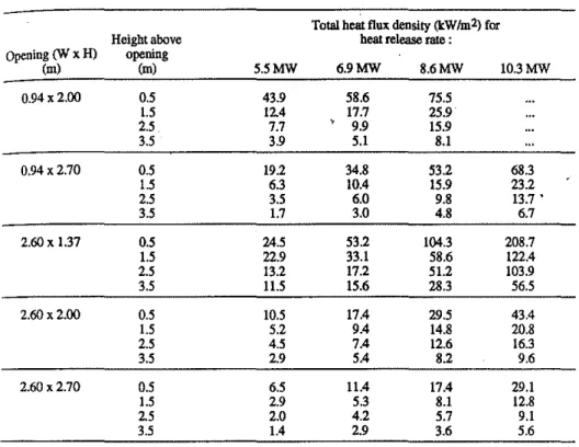
OLESZKIEWICZ ON FIRE TESTING AND REAL FIRE EXPERIENCE 131 Data frgm Propane Gas Fjres--The experimental fires were conducted using the larger test facility (Figure 1). Data collected in the
propane gas fires are summarized in Table 1.
TABLE I--Variation of time-averaged total heat flux density with heat
release rate, height above opening, and opening dimensions.
Total heat fluxdeuslty (kW/m2)for Height above heat releaserate :
Opening
CN
xH) opening (m) (m) 5.5MW 6.9MW 8.6MW 1O.3MW 0.94 x 2.00 0.5 43.9 58.6 75.5 1.5 12.4 17.7 25.9 2.5 7.7 9.9 15.9 3.5 3.9 5.1 8.1 0.94 x 2.70 0.5 19.2 34.8 53.2 68.3 1.5 6.3 10.4 15.9 23.2 2.5 3.5 6.0 9.8 13.7 • 3.5 1.7 3.0 4.8 6.7 2.60 x 1.37 0.5 24.5 53.2 104.3 208.7 1.5 22.9 33.1 58.6 122.4 2.5 13.2 17.2 51.2 103.9 3.5 11.5 15.6 28.3 56.5 2.60 x 2.00 0.5 10.5 17.4 29.5 43.4 1.5 5.2 9.4 14.8 20.8 2.5 4.5 7.4 12.6 16.3 3.5 2.9 5.4 8.2 9.6 2.60 x 2.70 0.5 6.5 11.4 17.4 29.1 1.5 2.9 5.3 8.1 12.8 2.5 2.0 4.2 5.7 9.1 3.5 1.4 2.9 3.6 5.6The data show that fire exposure to the exterior wall depends very much on both window opening dimensions and heat release rate. The wide and low window opening (2.6 m wide x 1.37 m high) provided the highest exposure. This can be explained by the velocity with which burning gases exit the fire compartment. The gases are driven by buoyancy, which increases with the height of the window opening. The low-velocity
flames issuing from the low window opening remained better attached to the wall above the window and transferred more heat to the wall than did the flames issuing from the taller windows.
Flame propagatjon oyer ComWlstjblg Claddjng System
The full-scale tests in the IRC/NRCC studies were conducted using a three-storey facility (Figure 1) providing fire exposure for 25 min. The fire exposure duplicated that recorded in wood crib fires. In those tests the average (during the steady statel heat flux density was
132 EXTERIOR INSULATION AND FINISH SYSTEMS
45 ± 5 kW/m2 measured 0.5 m above the opening and 27
±
3 kW/m2 measured 1.5 m above the opening on the noncombustible (marinite) cladding.VERTICAL CHANNEL TEST APPARATUS
TARGET WALL
BURN ROOM
FIGURE I--Full-scale test facility and vertical channel flame spread test apparatus
A representative set of combustible cladding systems was subjected to full-scale fire testing in order to evaluate the potential of flame spread. The same cladding systems were also subjected to a battery of smaller-scale fire tests in order to evaluate the applicability of these test methods for the assessment of flame spread potential.
The cladding systems evaluated included various insulations, sheathings and sidings, composite panels with plastic foam cores and FRP membranes and a large group of combustible exterior insulation systems applied to a noncombustible wall. Table 2 describes some of the tested assemblies, including the noncombustible wall {marinitel which was used for calibration and reference purposes.
The assemblies are grouped according to the flame spread distance recorded during the full-scale test. Assemblies 4.1, 4.2 and 4.3 showed flame spread to the top of the wall. ASSemblies 3.1 to 3.8 showed flame spread above the extent of the flame issuing from the window, but eventually the flame stopped and in most ゥョウエセョ」・ウL receded before the end of the test. Assembly No.2 did not show flame spread above the exposing flame, and Assembly No. 1 is the noncombustible wall.
p---OLESZKIEWICZ ON FIRE TESTING AND REAL FIRE EXPERIENCE 133 TABLE 2--Vertical flame spread distance and maximum heat flux densities
recorded in full-scale tests
Flame spread diS!. Heat flux density. kW1m2
Assembly [m] @3.5m @5.5m
1 Marinite over concrete block waIl 2.0' 16 10
2 Gypsum sheathing on glass fibre 3.0 15 10
insulated wood frame wall
3.1 Vinyl siding on gypsum sheathing on 3.0 23 17 glass fibre insulated wood frame walL
3.2 Aluminum siding on wood chip board 4.5 70 20 on glass fibre insulated wood frame wall
3.3 12.7 mm flame retardant treated plywood 3.0 29 20 on untreated wood studs. with phenolic
foam insulation in cavities
3.4 Aluminum sheet (0.75 mm) on flame 3.2 20 12
retardant treatedwoodstuds,with
,
phenolic foam insulation in cavities
3.5 EIFS with 76mmexpanded polystyrene 4.5 31 8 insulation, 7 mm resin modified coating
3.6 Composite panels (6 mm FRP membranes, 4.0 24 10 127mmpolyurethane foam core)
3.7 EIFS with 102mmexpanded polystyrene 4.5 48 37 insulation,3mm synthetic coating
3.8 EIFS with 76 mm expanded polystyrene 2.0 27 11 insulation, 3 mm synthetic coating
4.1 8 mm wood chip board on glass fibre 7.5 61 79 insulated wood frame wall
4.2 Vinyl siding on 8 mm wood chip board 7.5 82 111 on glass fibre insulated wood frame wall
4.3 Aluminum siding on 25 mm strapping, 25 mm 7.5 30 31 expanded polystyrene,19 mm plywood,
glass fibre insulated wood fmme wall a height of exposing flame
The division of the cladding systems into four groups corresponds to the fire hazard associated with the cladding's combustibility. Assembly No. 1 represents traditional noncombustible walls (masonry or concrete), which do not contribute any incremental fire hazard.
Assembly No. 2 was clad with gypsum sheathing which is not strictly "noncombustible" (contains two thin layers of paper), however, the incremental contribution of the combustible elements to fire hazard is negligible. Assemblies No. 3.1 to 3.8 pose some incremental hazard, which has to be evaluated and compared with acceptability criteria. Among those are EIFS systems, Assemblies No. 3.5, 3.7 and 3.8,
representing thick-coated EIFS with 76 nun (3") thick insulation, thin-coated EIFS with 102 rom (4") thick insulation and thin-thin-coated EIFS with 76 rom (3") thick insulation. Of all the EIFS tested, approximately 80% performed acceptably with regard to the requirements of the Canadian regulations (uP to 35 kW/m2 at 3.5 m and not mOre than 5 m flame spread distance). The test results indicate that エセ・ thickness of the foam
.\ 134 EXTERIOR INSULATION AND FINISH SYSTEMS
Assemblies No. 4.1 to 4.3 represent a significant fire hazard. considered by most to be unacceptable in high buildings.
Evaluatjon of Reduced Scale Tests
Conducting full-scale tests is costly and most testing
organizations do not have the facilities needed to carry out such tests. Consequently, NRCC has developed a less expensive reduced scale test. since the full-scale test is presumed to be representative of a typical fire scenario. good correlation of the results of a chosen reduced scale' test with the results of the full-scale test can be stipulated as an essential criterion.
The following four reduced scale test methods have been investigated:
Steiner Tnonel Test--Tests according to the Standard Method of セN
Test for Surface Burning Characteristics of Building Materials and, Assemblies CAN/ULC-Sl02/Sl02.2 (similar to ASTM E84, uses the same test apparatus but different calculation procedures), were conducted on all specimens to determine their flame spread ratings. Although the tunnel test method is able to differentiate between some of the specimens tested on the basis of their flame spread propensities, it is not able to adequately predict the full-scale performance of other types of wall assemblies (those that are made of multiple layers of composite
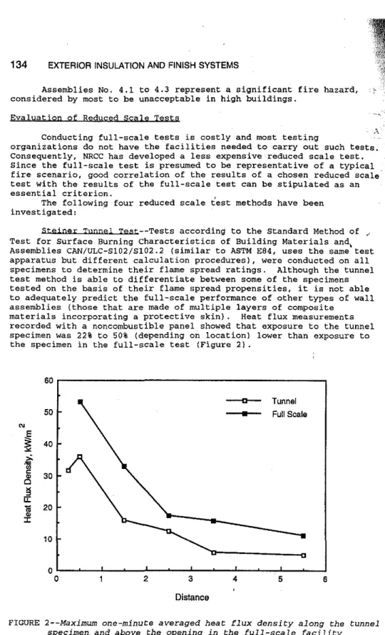
materials incorporating a protective skin). Heat flux measurements recorded with a noncombustible panel showed that exposure to the tunnel specimen was 22% to 50% (depending on location) lower than exposure to the specimen in the full-scale test (Figure 2).
60 50 N
.E
セ
40 セ Nセ 0 c 30 セ 0 セ II:m
20 J: 10 0 0 2 3 Distance 4 セ Tunnel • Full Scale 5 6FIGURE 2--Maximum one-minute averaged heat flux density along the tunnel specimen. and a-bove the opening in the full-scale facility
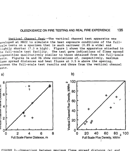
OLESZKIEWICZ ON FIRE TESTING AND REAL FIRE EXPERIENCE 135 yertjcal Channe] Tgst--The vertical channel test apparatus was developed at NRCC to simulate the heat exposure conditions of the full-scale tests on a specimen that is much narrower (0.85 m wide) and slightly shorter (7.3 m high). Figure 1 shows the apparatus attached to the full-scale test facility. The test gave indications of flame spread propensities qualitatively similar to those obtained from the full-scale tests. Figures 3a and 3b show correlations of. respectively, max1mum
flame spread distances and heat fluxes at 3.5 m above the opening, between the full-scale test results and those from the vertical channel tests.
+
20
40
60
80
2100
Full Scale Rux,oensity, kW/m
;
b)
'" 100 , - - - . . . , . ,
EセN
80
セ
セ
60
セu:
)40
() 20
i
8
2
4
6
Full Scale Flame Distance, m
8 , - - - ,
a)
E
FIGURE 3--Comparison between maximum [lame spread distance (a) and
maximum one-minute averaged heat flux density (b), in full-scale
test and in vertical channel test.
IMQ Surface Flammabjlity t・ウエセMtィ・ International Maritime
Organization (IMO) flame spread apparatus [7] was used to measure flame spread characteristics. There is not a good correlation between these results and those of the full-scale tests. This is attributed to the small size of the apparatus, which does not permit testing of the full thickness of a representative wall assembly nor does it allow the inclusion of all typical elements and features of the wall assembly (e.g., fasteners, expansion joints).
Mgdifjgd Standard Bpot peck Test--The standard (CAN/ULC-Sl07, UL 790, ASTM E-lOB) test apparatus was modified to provide exposure to a vertically mounted specimen. with its bottom edge adjacent to the burner slot. A steel grid was added above the burner to protect the burner from falling debris. The investigation indicated that this test method could not adequately and reliably predict the real fire performance of exterior wall assemblies because the lower heat exposure is insufficient to adequately challenge the specimens. The fire penetration into the tested assemblies was generally less than tQat observed in the full-scale tests. Consequently, assemblies with multiple layers of composite
- ; z
Aセ
, 0,z
,
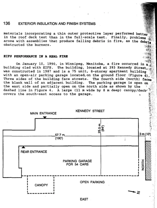
_____________ .J KENNEDY STREET PARKING GARAGE FOR 54 CARS MAIN ENTRANCEOn January 10, 1990, in Winnipeg, Manitoba, a fire occurred in building clad with EIFS. The building, located at 393 Kennedy was constructed in 1987 and is a 75 unit, B-storey apartment bUilding with an open-air parking garage located,on the ground floor (Figure 4),. Three sides of the building face streets. The fourth side (north) the blank wall of an adjacent building. The parking garage is open on the east side and partially open on the north side as shown by the dashed line in Figure 4. A large (11 m wide by 8 m deep) 」。ョッーケO、・」ォセ
covers the south-east access to the garage. EIFS PERFORMANCE IN A REAL PIRE
136 EXTERIOR INSULATION AND FINISH SYSTEMS
REAR ENTRANCE
materials incorporating a thin outer protective layer performed bette
in the roof deck test than in the full-scale test. Finally, problems
arose with assemblies that produce falling debris in fire, as the obstructed the burners.
セMMMMイMtMMMMMMMMMゥMMMMMMMMMMMMMMMMMM I : OPEN PARKING I CANOPY I
,
,
I ,!.._---.I
1--
LUWNWNセGlMMMMMMMKMMMMMMM⦅エ]⦅BQG (190') EASTFIGURE 4--Ground floor plan of 393 Kennedy Street
The building was not sprinklered except for the garbage chute and the garbage room. There were no fire detectors or sprinklers installed in the parking garage.
The building's exterior walls were covered with EIFS. Plastic foam insulation of different thicknesses was used on different portions of the facade. The EIFS was applied to an exterior grade gypsum sheathing on a steel stud frame or on masonrY. Most of the exterior walls of the building were also insulated with glass-fibre batts which filled the wall 'cavities between the steel studs. The foam insulation
OLESZKIEWICZ ON FIRE TESTING AND REAL FIRE EXPERIENCE 137 waS typically 76 rom HSセI thick, except in limited areas where thicker foam (140 rom (5 1/2·») was used to create architectural features. The north wall. located 3 m (10') from the adjacent building, was
constructed of masonry and insulated with the EIFS using the 140 rom (5 1/2") thick foam. No horizontal fire barriers (fire stopping) were incorporated within the EIFS.
The floor above the garage was a two hour fire resistance-rated reinforced concrete slab. A service space was created beneath this concrete slab by a suspended ceiling constructed of 16 rom (SIS") thick gypsum board. Rigid foam insulation 65 rom (2 1/2") thick was attached to the gypsum board from below and was covered on the garage side by an aluminum soffit.
The fire started in the garage and very quickly involved all 25 cars that were parked there. The flames issuing from the garage exposed and eventually ignited the EIFS on the exterior walls. The. fire spread on the facade extended to the top of the fourth storey, except for a narrow strip on the east facade, where the fire travelled up to the top of the seventh storey, and on the north facade, where the fire spread to the top of the wall.
The fire was extinguished quickly by the fire department using deluge and fog streams.
The rapid spread of fire throughout the parking garage can be, at least in part, attributed to the inadequate protection of the foamed plastic insulation board on the ceiling of the garage. This lightweight combustible thermoplastic insulation in the ceiling could have promoted fire spread in three ways:
reducing heat loss to the ceiling, thus allowing the initiating flames to stay hotter and extend farther horizontally than would be the case with a heat absorbing ceiling;
providing additional fuel to the flames travelling along the ceiling;
providing ignition sources to the cars, already preheated by the radiation from the flames at the ceiling, in the form of burning drops of molten plastic.
The damage to the concrete columns in the garage (spalled concrete) indicates that the fire in the garage was very intense and developed very rapidly.
In the central section of the east facade it can be estimated that the flames, originating in the garage, evidently reached the third storey. This is based on the marks left on the noncombustible portion of the facade (concrete block wall separating balconies) and on the damage to the EIFS below the balcony window on the third storey. This particular area could not have been damaged by flame propagation on the EIFS as it is isolated from the rest of the facade by non-combustible elements. Similar estimates cannot be made for other damaged areas because of the possible combination of the effects of the exposing
flames from the garage and the flame contributed by the EIFS.
Exposure to intense heat causes various degrees of damage to an EIFS, depending on the intensity and duration of the exposure. The damage results from shrinkage and melting of the plastic foam, decomposition of binders and melting of the reinforcing glass fibre mesh. The thermal destruction of an EIFS is usually accompanied by the combustion of gaseous hydrocarbons released by the decomposing organic components. A portion of the heat created by this combustion is fed back to the EIFS and helps in the further destruction of the system. The remaining heat is dispersed to the environment: In an extreme case, the
138 EXTERIOR INSULATION AND FINISH SYSTEMS
heat feedback from the burning wall is sufficient for destruction to continue, without any external heat exposure. This latter scenario would be expected to cause the fire to spread to the top of the wall; regardless of the height of the wall.
The damage to the EIFS in the 393 Kennedy Street fire was sUbstantial; however. in most areas it was as would be expected,
considering the fire to which it was exposed. There were two
.,:c"pt;!',n'
- a vertical strip on the East facade and the North facade. Both of these areas had 140 rom (5 1/2·) thick insulation board. In the NRCc research the thickest EIPS evaluated had 102 rom (4-) thick foam. However, there were other areas on the east facade where the thicker insulation board was applied and where fire spread was much less. Additional factors that could contribute to the extensive fire spread some areas, and not in others, were geometric factors. The north faced an adjacent building 3 m away. The vertical strip on the east facade was close to and downwind from the canopy. This area probably received a higher fire exposure than others. Such additional
could easily destroy the coating and force the fire into the foam.
A full description of the NRCC investigation of this fire can be found in Reference [8].
CONCLUSIONS
·'-'1:)
Certain combustible claddings can support unlimited vertical flame spread. Some combustible claddings, including the majority of EIFS used in North America, are not capable of sustaining vertical flame spread on their own (at a distance from the igniting window plume); these
claddings may be only marginal contributors to vertical fiie spread. Testing is needed to evaluate their flame spread propensity. Smaller scale test methods, including the standard Steiner tunnel test, the IMO surface flammability test, and the modified roof deck test methods, are not considered suitable for the assessment of the flame spread
propensity of combustible claddings. At this time, the full-scale test seems to be an appropriate means to distinguish between acceptable and unacceptable combustible claddings and exterior wall systems. The less expensive Vertical Channel Test should be considered for combustible cladding systems, such as EIFS, when only the surface flame spread is to be assessed.
The Winnipeg fire has brought three major problems to light: 1. The basic characteristics of any field-applied system should be the
same as those of a system tested for fire spread in a laboratory. Changing such characteristics as the foam thickness may change the
fire performance of the system.
2. The installation of fire stopping every storey or every second storey should be seriously considered especially when using combustible EIFS on high-rise buildings.
3. The potential severe fire hazard associated with an open parking garage that is not protected with any fire alarm or extinguishing system and exposes a building situated above it. A similar fire occurred in Richmond, British Columbia, in 1983. Poorly protected combustible insulation on the ceiling of 'the parking garages was the common factor in these fires.
p
OLESZKIEWICZ ON FIRE TESTING AND REAL FIRE EXPERIENCE 139 REFERENCES i1J [2 [ [3J 141 [51 [6J [7J [8J
andrus. J. and Petterson, 0., -Fire Hazards of Facades with Externally Applied Additional Insulation·, Report LUTVDG!(TVBB-3025), Lund Institute of Technology, Lund, Sweden, 1986.
Beitel, J.J. and Evans, W.R., -Multi-Story Fire Evaluation Program, Final Report, Volume I: Text: SWRI Project No. 01-6112-,
Department of Fire Technology, Southwest Research Institute, November 1980.
Rogowski, B.F.W., Ramaprasad. R., Southern, J.R., Fire Performances of external thermal insulation for walls of ュオャエゥセウエッイ・ケ「オゥャ、ゥョァウL
Building Research Establishment Report BR 135, Borehamwood. Hertfordshire, UK, 1988
Oleszkiewicz, l't -Fire Exposure to Exterior Walls and Flame Spread on combustible'C+adding-, Fire Technolggy, 26(4), QYYPセ pp.
357-340. .
ASTM E 5.11, Task Group 1, White Paper: -Assessing The Fire Performance Characteristics of Exterior walls·, 1989.
Oleszkiewicz, I., "Heat Transfer from A Window Fire Plume to A Building Facade", Collected Papers in Heat Transfer 1989, ASME, HTD-Vol. 123.
International Maritime Organization, Resolution A.516(14), "Recommendation on the Fire Test Procedures for Surface Flammability of Bulkhead and Deck Finish Materials (1985)". Oleszkiewicz, I., "Fire Performance of an Exterior Insulation system", Internal Report No. 596, Institute for Research in construction, National Research Council Canada, 1990.