Building Software Factories in the Aerospace Industry
by
Jose K. Menendez B.S. Aerospace Engineering University of Michigan, 1988
Submitted to the Department of Aeronautics and Astronautics in Partial Fulfillment of the Requirements for the Degrees of MASTER OF SCIENCE in TECHNOLOGY AND POLICY
and
MASTER OF SCIENCE in AERONAUTICS AND ASTRONAUTICS at the
Massachusetts Institute of Technology February 1997
© 1997 Massachusetts Institute of All Rights Reserved
Technology
Signature of Author:
January 17, 1997
Certified by:
John Deyst Professor of Aeronautics and Astronautics Thesis Supervisor
Accepted by:
Professor Richard de Neufville Chairman, Technology and Policy Program
Accepted by:
OF /
- Jaime Peraire
Profess of Aronautics and Astronautics Chair, Graduate Office
FEB
10 1997
Building Software Factories in the Aerospace Industry
by Jose K. MenendezSubmitted to the Department of Aeronautics and Astronautics in Partial Fulfillment of the Requirements for the Degrees of Master of Science in Technology and Policy and
Master of Science in Aeronautics and Astronautics ABSTRACT
The defense aerospace industry is currently in a phase of shrinking procurement budgets brought on by the end of the Cold War and pressures to reduce the national deficit and balance the Federal budget. Consequently, the Department of Defense has shifted its product development emphasis from system performance to system affordability. Simultaneously, software has become increasingly important for implementing
functionality in new systems and sometimes dominates total product development costs. The challenge for industry is to implement new processes and technologies that will allow the reliable, repeatable development of high quality software at reduced cost. One emerging practice capable of meeting this challenge is the software factory.
A software factory is an industrialized approach to software development which exploits technologies such as automatic code generation tools to secure cycle time reductions and quality improvements. Software factories also generate longer term savings by producing reusable assets suitable for future applications, allowing an organization to achieve economies of scope.
This thesis presents an overview of numerous technology development efforts in the aerospace industry which facilitate software factory development. A detailed case study of United Technologies is also presented. Productivity and quality metrics were collected to support a comparative analysis of the development of electronic engine control system software for the PW4000 Current and PW4000 Growth aircraft engines, which employed traditional and factory development methods respectively. Data reported by additional companies experimenting with software factory development has been compiled indicating that an immediate productivity improvement of 45% is consistent for the industry.
Despite clear successes, software factory processes are not in widespread use across the industry and experiences have been focused on a rather narrow range of applications for guidance, navigation, and control systems. Software factory processes have also been primarily applied in demonstration projects. Yet there are no insurmountable reasons why the software factory could not be applied to other software domains and production programs. This thesis closes with a discussion of challenges facing the widespread use of the software factory and the role policy plays in promoting its adoption.
KEYWORDS
automatic code generation, computer-aided software engineering (CASE), domain engineering, integrated environments, product-line development, software development productivity, software factory, software reuse, software quality
Thesis Supervisor: John Deyst
TABLE OF CONTENTS
BUILDING SOFTWARE FACTORIES IN THE AEROSPACE INDUSTRY ...1
CHAPTER 1: INTRODUCTION.. ... 9
Outline of Thesis ... ... 11
The Lean Aircraft Initiative and Acknowledgments... 13
CHAPTER 2: DEFENSE SOFTWARE DEVELOPMENT AND THE SOFTWARE FACTORY ... 15
Software Development in the Aerospace Industry... 15
Problems Affecting Software Development ... ... 20
T he Softw are F actory ... 23
Product-Line Application Development and Domain Engineering ... 24
Computer-Aided Software Engineering Technology... ... 25
Integrating CASE Technology into a Factory Support Environment... 26
CASE Tool Integration ... .... ... ... 29
Automatic Code Generation ... 32
Strategic M anagement... ... ... ... 35
CHAPTER 3: CASE TECHNOLOGY DEVELOPMENT IN THE AEROSPACE INDUSTRY ... 39
United Technologies / Pictures-to-Code ... ... 40
The Pictures-to-Code Process ... 40
The Pictures-to-Code Toolset ... 41
Automated Code Generation with PtC ... ... 43
G eneral Electric / BEA CON ... ... ... 47
The BEACON Integrated Environment ... ... 48
Integrated Systems, Inc. / MATRIXx ... ... 50
The M ATRIX x Product Fam ily ... .... ... ... 50
McDonnell Douglas / RAPIDS... ... ... 51
The RAPIDS Software Development Process ... ... 52
The RAPIDS Integrated Environment... ... 52
NASA-JSC / Rapid Development Lab ... ... 55
Lockheed / LEAP ... ... 56
The LEAP Integrated Environment ... .... ... . ... 56
Honeywell and the Domain Specific Software Architecture Program... ... ... 58
The D SSA Toolset ... 58
Charles Stark Draper Laboratory / CSDL CASE System ... 59
The CSDL CASE System ... 60
The SAO+SAGA Integrated Environment ... ... 62
S u m m ary ... 6 3 CHAPTER 4: INDUSTRY EXPERIENCES WITH SOFTWARE FACTORY DEVELOPMENT ... 65
United Technologies / Pictures-to-Code ... ... 65
Groundrules and Methodology for Pictures-to-Code Evaluation ... 65
The Pictures-to-Code Process... ... 66
Traditional versus Pictures-to-Code ... 69
Continuous Process and Toolset Improvement ... 74
The Japanese Software Factories... .. 77
Improving the Productivity and Quality of Software Development ... 80
The Benefits and Implementation of the Software Factory ... ... 84
CHAPTER 5: ASSESSING THE STATE OF THE SOFTWARE FACTORY ... ... 89
Diffusion of Software Factory Processes and Technologies ... 89
Challenges to Software Factory Adoption ... 94
Technology M aturity ... ... ... 94
Technology Domain Coverage ... ... 97
Technology M anagement ... ... ... 98
Product-line Scope ... ... ... ... 100
Software Ownership Rights... ... 101
A da versus C ... 102
The Role of Policy in Promoting the Software Factory ... ... 104
Areas for Further Research ... ... 106
LIST OF TABLES
TABLE 1.1 TYPES OF DOD COMPUTER SYSTEMS ... ... 10
TABLE 2.1 MIL-STD-498 SOFTWARE DEVELOPMENT ACTIVITIES ... ... 18
TABLE 2.2 MAJOR PROBLEMS OF TRADITIONAL SOFTWARE DEVELOPMENT ... 21
TABLE 2.3 ELEMENTS AND OBJECTIVES OF THE SOFTWARE FACTORY ... 23
TABLE 3.1 ENVIRONMENTS AND CASE TECHNOLOGY IN THE AEROSPACE INDUSTRY ... 39
TABLE 3.2 COMMON CHARACTERISTICS ... ... 64
TABLE 4.1 SOFTWARE PRODUCTIVITY ... ... ... 78
TABLE 4.2 SOFTWARE QUALITY ... 79
TABLE 4.3 % EFFORT BY SOFTWARE DEVELOPMENT ACTIVITY ... . 79
TABLE 4.4 ENCODING ERRORS IN AIRBUS SOFTWARE ... 82
TABLE 4.5 SHARED BENEFITS OF SOFTWARE FACTORY DEVELOPMENT ... ... .. 84
TABLE 4.6 SOFTWARE FACTORY IMPLEMENTATION ... ... 87
TABLE 5.1 OBSERVATIONS AND FINDINGS ON SW FACTORY DEVELOPMENT AND TECHNOLOGIES ... 89
TABLE 5.2 NATIONAL CRITICAL TECHNOLOGIES, SOFTWARE AND TOOLKITS AREA ... 90
TABLE 5.3 DOD PROGRAMS AIDING EMBEDDED SOFTWARE DEVELOPMENT ... 92
TABLE 5.4 CHALLENGES TO SW FACTORY ADOPTION ... 94
TABLE 5.5 DESIRABLE CAPABILITIES FOR AUTOCODERS... 97
LIST OF FIGURES
FIGURE 1.1 ANNUAL COSTS OF DOD COMPUTER SYSTEMS (ALL TYPES) ... ... 10
FIGURE 1.2 GROWTH OF AIRCRAFT SOFTWARE ... ... 11
FIGURE 2.1 DOD-STD-2167A SYSTEM DEVELOPMENT LIFE CYCLE ... 16
FIGURE 2.2 SOFTWARE ERROR TYPES DURING WEAPON SYSTEM DEVELOPMENT ... 22
FIGURE 2.3 THE THREE LEVERAGE POINTS OF SOFTWARE DEVELOPMENT ... 22
FIGURE 2.4 FORMS OF CASE INTEGRATION ... 28
FIGURE 2.5 LEVELS OF CASE TOOL INTEGRATION ... ... .30
FIGURE 2.6 NIST/ECMA REFERENCE MODEL ... ... ... 31
FIGURE 2.7 EVOLUTION OF CASE TECHNOLOGY... ... 33
FIGURE 2.8 AUTOMATIC CODE GENERATION BRIDGES THE GAP IN CASE TECHNOLOGY ... 34
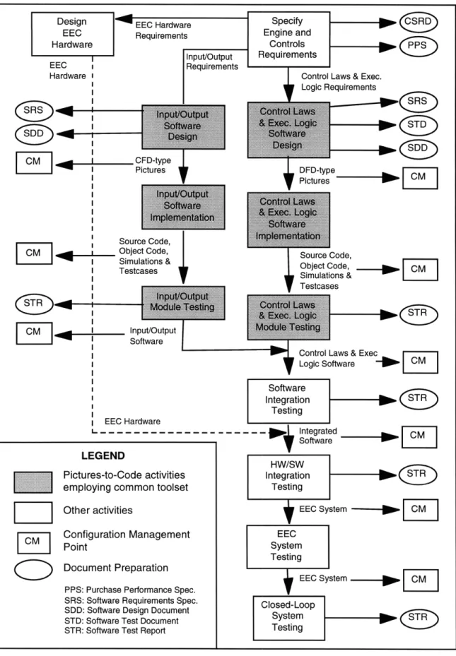
FIGURE 3.1 OVERVIEW OF THE COMMON DEVELOPMENT PROCESS FOR EEC SOFTWARE ... 42
FIGURE 3.2 FUNCTIONAL VIEW OF THE PICTURES-TO-CODE TOOLSET ... 43
FIGURE 3.3 CONTROL FLOW DIAGRAM AND STANDARD PART ... ... 45
FIGURE 3.4 DATA FLOW DIAGRAM AND STANDARD PART ... ... ... 46
FIGURE 3.5 THE BEACON ENVIRONMENT ... ... ... 49
FIGURE 3.6 SAMPLE SYMBOLS FROM BEACON... ... 49
FIGURE 3.7 THE RAPIDS SOFTWARE DEVELOPMENT PROCESS ... .. ... 53
FIGURE 3.8 THE RAPIDS ENVIRONMENT ... ... 54
FIGURE 3.9 LOCKHEED ENVIRONMENT FOR AUTOMATIC PROGRAMMING... 57
FIGURE 3.10 CSDL CASE SYSTEM ... 61
FIGURE 4.1 OVERVIEW OF THE COMMON DEVELOPMENT PROCESS FOR EEC SOFTWARE ... 68
FIGURE 4.2 % MODULE CYCLE TIME, 4000 CURRENT VS. 4000 GROWTH ... ... 72
FIGURE 4.3 DETECTED PROCESS ERRORS, 4000 CURRENT VS. 4000 GROWTH ... ... 72
FIGURE 4.4 MODULES CHANGED BY DEVELOPMENT METHOD VS. YEAR ... ... 73
FIGURE 4.5 % MODULE CYCLE TIME VS. YEAR, ALL LARGE COMMERCIAL PROGRAMS ... 73
FIGURE 4.6 DETECTED PROCESS ERRORS VS. YEAR, ALL LARGE COMMERCIAL PROGRAMS ... 74
FIGURE 4.7 % ERRORS BY PROGRAM VS. VERIFICATION ACTIVITY ... ... 76
FIGURE 4.8 % ERRORS BY VERIFICATION ACTIVITY FOR PTC METHOD ... 76
FIGURE 4.9 % ERRORS BY TYPE FOR PTC METHOD ... ... ... 77
FIGURE 4.10 COMPARISON OF PRODUCTIVITY INCREASES ... ... 81
FIGURE 4.11 COMPARISON OF REDUCTIONS TO ENCODING ERRORS ... 83
Chapter 1: Introduction
The United States military has become dependent on all types of computer systems to accomplish its mission as shown in Table 1.1. In 1995 alone, the Department of Defense
spent nearly 43 billion dollars to purchase computer systems (STSC, 1994). Only 7 billion of this expenditure purchased hardware, with the remaining 35 billion dollars going
towards the development and maintenance of software. Software has become the major factor affecting the cost of computer systems and the cost growth in software has also outpaced the cost growth in hardware. Figure 1.1 shows the costs for all Department of Defense computer systems for a period from 1985 to 1995 (STSC, 1994). Hardware costs increased by a factor of 2 while software costs increased by a factor of 3.
One of the many types of DoD software contributing to this cost growth is the real-time software embedded in weapon systems such as aircraft. Real-real-time embedded software has become increasingly important for implementing avionic systems functionality in all types of aircraft. Avionic systems in modem defense aircraft are highly sophisticated and complex. They are composed of multiple subsystems (navigation, radar, flight control,
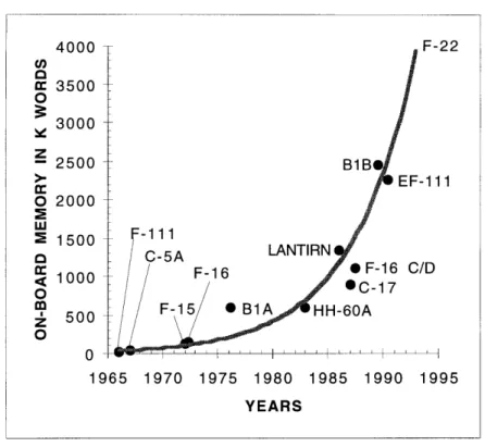
engine control, warfare systems, etc.) distributed over multiple processors throughout the aircraft. Software is embedded into each subsystem and is used to provide for overall system integration, making it critical to both the mission and safety of the aircraft. The increasing dependence of aircraft systems on embedded software is evident in Figure 1.2
(Babel) which illustrates an exponential growth of on-board memory size.
The growth in development costs and the amount of software to be developed have combined to form a major challenge for the aerospace industry: to develop high quality software in a reliable, repeatable manner while improving productivity. New processes and technologies are constantly being implemented to meet this challenge. One emerging
Table 1.1 Types of DoD Computer Systems
Embedded Systems
Command and Control Systems
Intelligence and Cryptological Systems All other weapon
Information System Resources Automated Information Systems Information Resource Management All other non-weapon
Figure 1.1 Annual Costs of DoD Computer Systems (all types) 45.0 40.0 35.0 30.0 c 25.0 o 20.0 15.0 10.0 5.0 0.0 LO CD I C cc 0) 0 - 3 O CC ) c cc cc cc ) C) 0 ) M) ) Year
Figure 1.2 Growth of Aircraft Software
practice, attempting to change the nature of software development from a craft to mass production, is the software factory.
Many organizations within the aerospace industry have begun to build software factories. A software factory is an industrialized approach to software development with the goal of using systematic reuse of design specifications to achieve economies of scope. This thesis takes an in depth look at the software factory and the technologies which support
software factory development in an attempt to determine the impact they are having on the
industry.
Outline of Thesis
Chapter 2 provides the context for the thesis by presenting an overview of the development of software for Department of Defense weapon systems. The chapter also introduces the concept of a software factory in greater detail. Added emphasis is given to
4000 F-22 u, 9 3500 O 3000 z 2500 B1B > EF-111 O 2000 2 1500 -111 SC-5A LANTIRN 1000 i F-16 * F-16 C/D o *00 OC-17 500 F-15 BlA HH-60A 500 0 ' 1965 1970 1975 1980 1985 1990 1995 YEARS
supporting practices such as the integration of computer-aided software engineering (CASE) technologies into a software factory environment and the use of automatic code generation.
Chapter 3 presents an overview of numerous technology development efforts in the aerospace industry. A description of integrated environments and CASE technologies developed by aerospace corporations, commercial tool vendors, and government agencies is included. Common characteristics of the technologies resulting from these parallel efforts are compiled.
Chapter 4 discusses experiences within the aerospace industry with using these technologies and other software factory practices. A case study of software factory
development at United Technologies forms the bulk of this chapter. Software developed for similar products and created by different development practices (traditional and factory) forms the basis of a comparative analysis. This analysis quantifies the impacts of factory practices on the productivity and quality of the development process. Data from additional companies has also been compiled in an effort to determine if the experiences of United Technologies are consistent with others in industry and to identify the expected benefits of implementing a software factory.
Chapter 5 begins with a summary of observations and findings. A diffusion model illustrating the widespread industry adoption of the software factory for production
programs is presented and followed by a discussion of issues requiring resolution. The thesis concludes with policy recommendations and the identification of areas for further research.
The Lean Aircraft Initiative and Acknowledgments
The research of this thesis has been supported by the Lean Aircraft Initiative (LAI). Sponsored by the U.S. Air Force and private corporations, the LAI is a research program jointly managed by the USAF Aeronautical Systems Center and the Massachusetts Institute of Technology. The LAI mission is to "define and help implement roadmaps for
fundamental change in both industry and government operations, based on best "lean" practices, resulting in: greater affordability of systems, increased efficiency, higher quality, enhanced technological superiority, and a stronger U.S. defense aircraft industrial base."
The LAI takes a broad view of the defense aircraft industry, encompassing all sectors of defense aircraft production, including airframe integrators and major supplier groups, such as producers of engines, avionics and electronic systems, and other equipment suppliers. The program has undertaken research in five major areas: Product Development, Factory Operations, Supplier Systems and Relationships, Organization and Human Resources, and Policy and External Environment.
There are numerous members of the Product Development Focus Group whom I wish to recognize for their contribution to this thesis. I wish to thank John Deyst, Charlie Boppe, Dave Hoult, John Miller, and all the other MIT members of LAI who provided encouragement and guidance. Also, I wish to thank the many from industry, including Al
Klein (Hamilton Standard), Jim Krodel (Pratt & Whitney), J.J. Liu (Hughes), and Marvin Ross (Hughes), who provided data and critical feedback. Their time and cooperation are
greatly appreciated. Although supported by LAI, the opinions expressed in this thesis are strictly those of the author and not those of LAI sponsors.
Chapter 2: Defense Software Development and the Software Factory
A major challenge for the defense aerospace industry is to develop high quality software in a reliable, repeatable manner while improving productivity. New processes and technologies are constantly being developed to meet this challenge. These developments have led to the emergence of the software factory. This chapter establishes the context for the thesis by presenting an overview of the development of software for Department of Defense weapon systems and providing a detailed introduction to the software factory and its supporting practices.
Software Development in the Aerospace Industry
Software development in the aerospace industry has been greatly influenced by the acquisition management practices of the Department of Defense. These practices include the creation of standards for software development and documentation; such as DOD-STD-2167a, DOD -STD-7935a, DOD -STD-1703, and MIL-STD-498; and the evaluation of the software development capabilities of government contractors. Standards are used to guide the activities of defense contractors by defining processes, methods, and engineering practices. Although recently superseded for new system acquisitions by MIL-STD-498, the long-standing DOD-STD-2167a had been the primary standard and has had a significant impact on software development. It specified the process for developing mission critical software for all military systems and defined standards for requirements specifications, traceability and documentation.
Figure 2.1 illustrates the life cycle and structured approach specified in DOD-STD-2167a. The process starts with users and systems analysts defining system level
Hardware (HWCI) Development
and software development efforts begin. Hardware and software requirements analyses are conducted to determine partitioning, with traceability back to all system requirements.
Requirements analysis is followed by the design phase, broken into preliminary and detailed design. The preliminary design phase defines the software architecture and allocates software functional requirements to program modules. The detailed design phase defines the internal specifics of each module and intermodular interfaces. The designs require implementation and testing. Implementation includes coding, debugging and re-coding (if necessary) while testing involves increasing levels of integration. First individual software modules are tested, followed by the testing of a complete software build. Finally the hardware and software are integrated and tested as a system. The maintenance phase occurs after the system is deployed. This phase primarily involves defining improvements and new system requirements, but may also find errors not detected during testing.
The DOD-STD-2167a process reflects a classic waterfall life cycle which implies that each phase is completed only once and in sequence. In reality, developing software is a very iterative process with many phases occurring simultaneously. Correct and complete requirements are rarely fixed when system development begins. Iteration allows re-evaluation of requirements until operational needs are fully met. Many other life cycle
models have evolved from the waterfall model to capture the iterative nature of the software development process. These include the iterative waterfall, the spiral and the prototyping models. Additionally, new software development processes have been developed such as object-oriented programming, which advocates a bottom-up methodology.
The Department of Defense has recently issued MIL-STD-498 to accommodate these new life cycle models and development methods. This new standard specifies requirements for 19 activities, Table 2.1 (Defense Acquisition University, 1996). It
emphasizes flexibility by stating that these activities may overlap, can be applied iteratively, can be applied differently to different types of software, and need not be performed in the
Table 2.1 MIL-STD-498 Software Development Activities
1. Project Planning and Oversight
2. Establishing a Software Development Environment 3. System Requirements Analysis
4. System Design
5. Software Requirements Analysis
6. Software Design
7. Software Implementation and Unit Testing 8. Unit Integration and Testing
9. CSCI Qualification Testing
10. CSCI/HWCI Integration and Testing 11. System Qualification Testing
12. Preparing for Software Use 13. Preparing for Software Transition 14. Software Configuration Management 15. Software Product Evaluation
16. Software Quality Assurance 17. Corrective Action
18. Joint Technical and Management Reviews 19. Other Activities
listed order. MIL-STD-498 is consistent with the acquisition reform initiatives of Defense Secretary William Perry who stated standards should be viewed as tools for guidance instead of strict requirements.
Regardless of which software development process an organization selects, the organization must have an effective management capability in order to repeatedly adhere to the process. The Software Engineering Institute has created a framework for describing an organization's process capability called the Capability Maturity Model for Software (Paulk,
1993). The Capability Maturity Model (CMM) includes five maturity levels which describe a path from ad hoc, chaotic processes to mature, disciplined software processes.
The five maturity levels of the CMM are:
1) Initial: The software process is characterized as ad hoc, and occasionally even chaotic. Few processes are defined, and success depends
on individual effort.
2) Repeatable: Basic project management processes are established to track cost, schedule, and functionality. The necessary process discipline is in place to repeat earlier successes on projects with similar applications. 3) Defined: The software process for both management and engineering activities is documented, standardized, and integrated into a standard software process for the organization. All projects use an approved, tailored version of the organization's standard software process for developing and maintaining software.
4) Managed: Detailed measures of the software process and product quality are collected. Both the software process and products are quantitatively understood and controlled.
5) Optimizing: Continuous process improvement is enabled by quantitative feedback from the process and from piloting innovative ideas and technologies.'
The CMM is used as a map for either a software process assessment or a software capability evaluation to appraise the maturity of an organization's execution of the software process. Software process assessments are used to determine the state of an organization's current software process, to determine the high-priority issues related to the organization's
software development process, and to obtain the organizational support for software process improvement. Software capability evaluations are used by the Department of Defense to identify contractors who are qualified to perform the software work or to
'Paulk, Mark C.; et al: The Capability Maturity Model For Software, Version 1.1, Software Engineering Institute Report No. CMU/SEI-93-TR-24, Carnegie Mellon University, 1993, Chapter 2.
monitor the state of the software process used on an existing software effort. Software capability evaluations are typically conducted by independent evaluation teams.
Problems Affecting Software Development
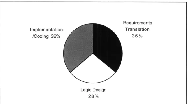
Difficulties persist with weapon systems software development despite Department of Defense efforts to positively influence software development management by defense contractors. Traditional software development is characterized by a hand-crafted approach with different specialists responsible for separate phases (i.e. requirements analysis, design, implementation, test and maintenance). The numerous problems with this approach, Table 2.2 (Hopkins, 1993), result in the introduction of errors, Figure 2.2 (Babel). The labor intensive nature of the craft approach also affects quality, which is difficult to maintain and control when large development teams are required, and often results in diseconomies of scale. It is common for average productivity to decrease as the number of developers on a project increases. Frequently, the end result is cost and schedule overruns as all detected errors must be removed before high quality software can be
fielded.
People, process, and technology are the major determinants of software quality and productivity, Figure 2.3 (Over, 1992). Together these three form the leverage points which must be addressed in order to attack the problems of traditional software development and reduce costs. One such holistic approach to software development is the software factory.
Implementation /Coding 36% Requirements Translation 36% Logic Design 28%
Figure 2.2 Software Error Types During Weapon System Development
Figure 2.3 The Three Leverage Points of Software Development
PEOPLE
PROCESS TECHNOLOGY
Major determinants of software cost, schedule, productivity, and quality
The Software Factory
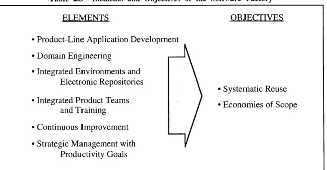
A software factory is an industrialized approach to software development with the goal of using systematic reuse to achieve economies of scope, Table 2.3. Economies of scope can be achieved within a software organization by reusing software assets across multiple projects. Software factories are characterized by the extensive use of highly
integrated computer-aided software engineering (CASE) technologies to form environments supporting process automation, with electronic repositories to store and retrieve software assets. By using standardized automation based development processes, software factories are able to leverage the efforts of personnel toward the early phases of development and implement product teams. Additionally, commitments to continuous improvement and
strategic management insures that the factory incorporates the latest development techniques and technologies. Strategic management also involves establishing productivity goals for the software factory and actively addressing any organizational resistance to factory implementation.
Table 2.3 Elements and Objectives of the Software Factory
ELEMENTS OBJECTIVES
* Product-Line Application Development * Domain Engineering
* Integrated Environments and Electronic Repositories
* Systematic Reuse
* Integrated Product Teams *Economies of Scope
and Training * Continuous Improvement * Strategic Management with
Product-Line Application Development and Domain Engineering
Software factories achieve reuse across projects by focusing on a single product line aided by domain engineering. A product-line is a family of systems that possess similar functionalities and share a common architecture. A software-intensive product-line can be either narrowly defined, such as radar systems or GPS-based navigation systems, or more broadly defined, such as fighter aircraft or airlifter. Product-line application development creates new software systems by incrementally building or extending from a common architecture through the assembly of reusable assets.
To support product-line application development, software assets (specifications, code, etc.) must be designed with reuse in mind, which is made possible by domain engineering. A domain is a distinct functional area within an underlying set of common requirements and capabilities. Control systems is an example of a software domain. There may be more than one domain within a given product-line and a given domain may support multiple product-lines.
Domain engineering involves those engineering activities necessary to implement a planned, systematic, product-line based reuse strategy. This strategy often includes: economic analysis, domain scoping and domain analysis, domain specific architecture design, reusable component development, domain-specific software tool development, and reuse process definition and documentation. ... Domain engineering defines which processes, methods, tools, and procedures to use to engineer the software product.2
2 Software Technology Support Center (STSC): Guidlines for Successful Acquisition and Management of
Computer-Aided Software Engineering Technology
Computer-Aided Software Engineering (CASE) is the use of support tools to automate much of the software development process. Automation of the implementation and testing phases can be used to reduce the overall labor requirement, significantly reduce errors introduced during coding, and provide leverage toward the front-end stages of the process. Additionally, providing automated support for analysis and design can eliminate many of the errors that occur during the requirements stage of development while
improving the reuse of software components. Jones and Turkovich provide further emphasis on the benefits of automation technology:
In order to achieve significant reductions in software costs it is necessary to treat the software problem not merely as a managerial problem but as a technological problem. By doing so, the software development process becomes automation based, as opposed to automation assisted. This automation based system is supported with knowledge acquired by experts as they interact with the system in operation. In this way, software development leverages accumulated knowledge that can be used from application to application. Instead of people acting as bottlenecks in a flow to analyze functionality, they serve to fine-tune accumulated knowledge as
appropriate on new projects.3
There are many uses for CASE technology. CASE technology can be used to enforce process control, ensuring that the process is disciplined and repeatable, and to automate source code generation, eliminating manual errors and reducing the need for debugging. Other labor-intensive tasks can also be automated, allowing software
development by small teams while leading to a reduction in cycle time and a shift of focus to requirements analysis rather than implementation. CASE technology can also be used to
3 Jones, Denise; and Turkovich, John; et al: "Automated Real-Time Software Development," Proceedings of the 3rd National Technology Transfer Conference & Exposition, NASA Conference Publication 3189, Volume 2, 1993, p. 184.
collect metric data, facilitating process improvement and schedule and cost estimation. However, before CASE technology can be introduced to improve both the quality and productivity of a software development process, the process must be clearly defined and should reflect the fundamentals of engineering practice. Furthermore, to fully benefit from all the capabilities of CASE technology, extensive integration into a cohesive software factory environment is required.
Integrating CASE Technology into a Factory Support Environment CASE technology includes both individual CASE tools and integrated CASE environments. There are two nonexclusive approaches to improving software quality and productivity, a micro-management approach and a macro-management approach (Sage and Palmer, 1990). A micro-management approach attempts to achieve incremental
improvements in the various phases of a software development process but leaves the overall process unchanged. A macro-management approach is systemic and holistic, attempting to achieve improvements by addressing the software development process in its entirety. Implementing individual CASE tools is a micro-management approach that frequently fails to achieve the desired results. A software factory requires an integrated environment to support and facilitate its practices.
Keith Bennett compiled a collection of research papers in his book on software engineering environments (Bennett, 1989). In the first part of Bennett's book, dedicated to Software Factories, Christer Fernstrom's chapter reemphasizes the need for a holistic approach to integration while discussing the evolution of CASE technology integration towards a Software Factory Support Environment:
Many development activities have, of course, long been supported by tools, and recent years have seen improvements in increased coverage and in tool quality. But it is still mainly the responsibility of the individual to effectively coordinate the use of tools. As the word 'tool' implies it is an approach to craftsmanship.
The need for a more industrial approach has long been recognized. It has been one of the major driving forces behind the increasingly ambitious efforts to tool integration. An early example of this is the integration of a compiler, and editor and a debugger into a Programming Support Environment. The next step was the inclusion of design tools, version management capabilities, document support, etc. into what is known as Software Development Environments. Now emerging IPSEs (Integrated Project Support Environments), providing total coverage for a whole project, including for example project management support, represent the next step.
A Software Factory represents yet another step. As the word 'factory' implies it aims at a more industrialized approach to software production. In particular, the Software Factory differs from the previous steps in that it represents a 'people centered view', because it is not only a support environment; it also explicitly includes the integration of people and their 'corporate knowledge'; their organization, their rules and policies, their
methods etc.
The inclusion of people into the system under consideration puts a very important interface in focus: the interface between the people part of the factory and the non-people part - the Factory Support Environment (FSE). The effectiveness of the entire factory is crucially dependent on the quality of this interface, because it determines whether the FSE is a true support to the organization.4
Implementing integrated CASE environments, such as a Factory Support
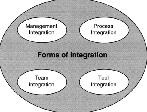
Environment, is a macro-management approach. Integration is key to achieving significant improvements in quality and productivity. Figure 2.4 shows the four important forms of integration required to create a fully integrated CASE environment -process, team, management, and tool (Bell and Sharon, 1995).
4 Bennett, Keith (ed.): Software Engineering Environments: Research and Practice, Ellis Horwood Ltd., 1989, p. 18.
Figure 2.4 Forms of CASE Integration
Process integration refers to using CASE tools that collaborate specifically to support the process and span the process life cycle. The process should not only identify the phases and tasks of software development but it should also identify the tools for each task and the sequence of their use. The tools should also provide for configuration control.
Team integration, or organizational integration, refers to integrating the Factory Support Environment and the organization. For example, tools can be used to electronically network software development teams. The tools should provide for communication and shared access to data while maintaining data integrity. Team integration provides for the "people centered view" of a software factory.
Management integration refers to using CASE tools to control and monitor software development. The tools should collect cost, productivity and quality metrics to allow
Tool integration refers to using CASE tools that share user-interfaces, data and functionality. A detailed discussion of tool integration is presented in the next section of this thesis.
The four forms of integration capture the essential capabilities of an integrated CASE environment: process management, project management, requirements management, configuration management, document management, a repository, and project verification and validation. In addition, the environment should be flexible, extendible and capable of supporting an organization working on multiple projects.
CASE Tool Integration
Of the four forms of integration, tool integration has been the subject of greatest focus. Tool integration addresses the mechanisms of linking individual CASE tools together. There are three dimensions of tool integration -user-interface or presentation integration, data integration and control integration. User-interface integration refers to using a common look and feel among various CASE tools to facilitate ease of use and quick learning. Data integration refers to the representation, conversion and exchange of data in a common standard. It determines to what degree data generated by one tool can be accessed and understood by another. Control integration refers to tool invocation, shared
functionality, and the ease of communications between tools. Data and control integration are closely related because tools share functionality by exchanging control messages that contain data and data references. Tools are called interoperable when full data and control integration exists between them.
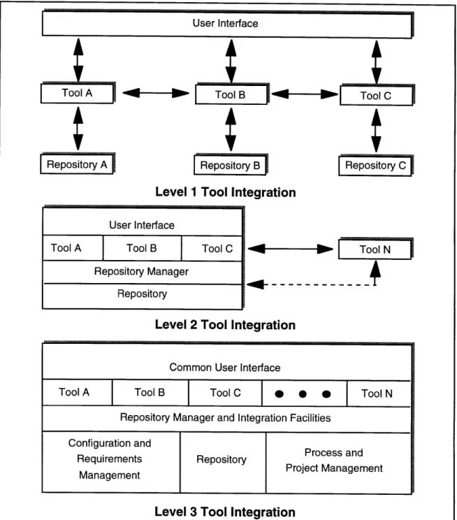
Figure 2.5 shows three levels of tool integration (Bell and Sharon, 1995), which are dependent upon how the tools are developed. Level 1 encompasses tools developed individually. Such tools are likely to have common user interfaces and data import/export formats but are unable to share a single repository. Level 2 encompasses tools developed as a suite. They are tightly integrated and optimized amongst themselves but their integration
STool B ToolC
Repository B Repository C
Level 1 Tool Integration
User Interface
Tool A Tool B Tool C Tool N
Repository Manager Repository
Level 2 Tool Integration
Level 3 Tool Integration
Figure 2.5 Levels of CASE Tool Integration
User Interface i
t
A
Reposito;yeostr AliFigure 2.6 NIST/ECMA Reference Model
with other tools remain at a Level 1 capability. Level 3 encompasses tools developed to meet formal interoperability standards such as accredited ANSI standards. These tools may have been developed individually but together they are capable of forming a highly
integrated environment.
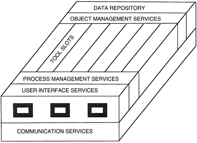
The "toaster" model, Figure 2.6, represents another form of Level 3 tool integration. The "toaster model" is a reference model for an integrated environment developed by the National Institute of Standards and Technology in conjunction with the Europe Computer Manufacturers Association. The model is not an implementation but rather a conceptual framework that includes a catalog of services an environment could provide (NIST/ECMA, 1993). One goal of the model is to be able to define points at which interoperability standards may be useful.
Automatic Code Generation
Software factories involve systematic reuse and the use of automation technologies to leverage efforts toward the early phases of software development. Figure 2.7 shows the evolution of CASE technology leading to automatic code generation (Fisher, 1988). Automatic code generation is an emerging CASE technology that aids software factories in both systematic reuse and leverage by allowing a change in focus from the reuse of code to the reuse of design specifications, which is potentially more cost-effective.
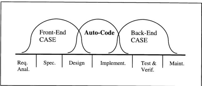
CASE technologies fall into two general groups, Front-End CASE and Back-End CASE (Schefstrom, 1993). Front-End CASE, or Upper CASE, includes graphical notations, editing tools, and other technology developed to support the early requirements and design phases of the software development life cycle. Back-End CASE, or Lower CASE, includes compilers, debuggers, and other technology developed to support the later phases of the life cycle. Figure 2.8 illustrates how automatic code generation bridges the gap between these two groupings of CASE technology by automating the implementation phase while taking advantage of existing technologies like compilers and graphical editors. Automatic code generators must be integrated into any environment if that environment is to support the full life cycle of software development.
Automatic code generation improves both quality and productivity. Producing defect free source code eliminates implementation errors which are one-third of the errors affecting weapon system development, as shown in Figure 2.2. Automating the coding process, a labor intensive task, is necessary to increase productivity. In fact employing CASE technology that delivers a design only, requiring manual implementation of code, can potentially reduce productivity. Employing CASE technology, with full automatic code generation, can create an environment that will increase productivity and reduce errors.
Figure 2.7 Evolution of CASE Technology
Figure 2.8 Automatic Code Generation bridges the gap in CASE Technology
Automatic code generation is the ultimate goal of most CASE tool vendors and certainly of all CASE tool users. Code generation is the ability to automatically generate working or compilable software directly from a design specification. Ultimately, the software designer's time is much better invested in fleshing out application specifications and architectures rather than in coding and debugging. Unfortunately truly generalized code generation is not available but code generation is available in a variety of focused tools. Code generation is a bottleneck in CASE technology.5
Fisher's assessment still holds today. There is no extensive use of generalized code generation in the defense aircraft industry. However there are several examples of the successful use of automatic code generation to create software for aircraft subsystems, discussed in detail in Chapters 3 and 4. Capable automatic code generators for guidance, navigation and control subsystems exist. Engineers have historically used block type diagrams to specify the detailed design of these subsystems. These code generators employ graphical editors used to create detailed design diagrams and multi-lingual translators used
to convert the diagrams into source code. Details of the programming language are hidden from the system designer. Automatic code generation also improves productivity by facilitating component reuse.
Component reuse, of course, does not just mean the reuse of code. It is possible to reuse specifications and designs. The potential gains from reusing abstract products of the development process, such as specifications, may be greater than those from reusing code components. Code contains low-level detail which may specialize it to such an extent that it cannot be reused. Designs or specifications are more abstract and hence more widely acceptable.6
Software factories support component reuse by storing reusable design
specifications in a electronic repository. These specifications can be retrieved from within a graphical editor to be incorporated into new applications and then automatically translated into code. If modifications to the specification are necessary, they can be readily created within the graphical editor. Reuse of design specifications with multi-lingual automatic code generators does not confine the application to a predetermined programming language. Also, reuse of design specifications aids portability, allowing the reuse of software across different operating systems and processors.
Strategic Management
Strategic management is an important aspect in any successful attempt to build a software factory. The problems plaguing software development are interrelated, difficult to separate and inherently systemic. Strategic management involves pursuing integrated solutions by combining organization, process, design, CASE technology and training to complement and reinforce each other.
This review of problems and solutions in software engineering suggests several observations. Individual engineers and managers know what difficulties they are likely to face, and they have a variety of tools, techniques and concepts to help them. Phases of the development process are interrelated, however, and large projects require many individuals and groups to complete and maintain. Meanwhile, companies continue to face shortages of experienced software personnel and engineers while programming tasks continue to grow in size, complexity, and costs. The result is that discrete solutions, such as in the form of stand-alone tools and techniques, are inadequate to address all the problems organizations face in managing software development.
Boehm and a colleague reinforced this argument in a 1983 article. Their studies of software cost and productivity at TRW, as well as of project performance at other firms, all pointed to the need for comprehensive, strategic efforts on the part of management. They noted that, "Significant productivity gains require an integrated program of initiatives in several areas, including tools, methods, work environments, education, management, personal incentives, and reusability." As for the benefits of such an approach, their studies indicated that, "An integrated software productivity program can produce productivity gains of factors of two in five years and factors of four in tens years, with proper planning and investment." Yet they did not suggest firms could achieve such gains easily, and warned that, "Improving software productivity involves a long, sustained effort and commitment."7
When implementing a software factory, management must assume a long-term view and link process improvements, research and development, training, and organizational changes to form an integrated approach. Also, clear quality and productivity goals should be established prior to embarking on any strategic initiatives. Initiatives include the
definition of the product-line, the analysis and standardization of the software development
process, investment in integrated CASE technologies, the active promotion of reuse, and the mitigation of resistance.
Process analysis and standardization must be completed prior to committing to specific CASE technologies. The process drives tool selection. Case studies have shown that building an integrated CASE environment can take years of effort. In addition to procuring commercially available CASE tools, building an environment may also require in-house development of CASE tools, which themselves may be specific to a particular domain of application or product-line. And these tools must be flexible enough to support a common process and integrated environment for use across multiple projects.
Training is an additional factor which must be implemented as an integral part of software factory development. Training must include teaching the common process and tool usage to make the development of quality software repeatable and predictable. An important focus of training is to improve employee skill-sets by also teaching the principles of high-level systems design, requirements analysis, team management and
communication. CASE technology can be met with resistance due to the tendency of automation to reduce skills. But it also breaks barriers of the distinct functional roles between systems and software engineering. Expanding the focus of training beyond tool usage is a strategy for leveraging the front-end of the development process. This allows the linking of CASE technology with organizational changes such as developing software with small integrated product teams in a product-line approach.
Strategic management also involves attention to reuse. Reuse can also be met with resistance and must be actively planned for and encouraged before it is likely to become systematic. Systematic reuse is the highest level of a scale also including ad hoc and opportunistic reuse.
Ad hoc reuse is a programmer's or workgroup's sporadic use of previously developed code. There is no defined reuse process for identifying and exploiting reuse opportunities, and success relies on the individual's initiative. Opportunistic reuse is characterized by identifying reusable assets
and applying them in a development effort where the software developer identifies and locates the applicable reuse components. This type of reuse is generally project-specific where a general reuse requirement is most likely defined in the project plan. Systematic reuse is reuse planned over a family of product developments with a robust, flexible architecture, where families of reusable assets are developed and maintained to provide large-scale reuse. With this type of reuse, new opportunities for reuse, based on
anticipated customer needs and technology innovation, are created.8
8 Department of Defense: DoD Software Reuse Initiative: Strategic Plan, Document No. PD436.6,
Chapter 3: CASE Technology Development in the Aerospace Industry
Numerous development efforts have been underway in the aerospace industry to develop computer-aided software engineering (CASE) technologies that support the creation of software factory support environments. These development efforts involve the creation of integrated environments themselves or enabling technologies like automatic code generation. This chapter provides an overview of some of the development programs and a description of the resulting environments and enabling CASE technologies.
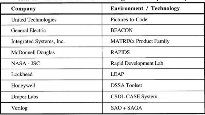
Technology development has been underway at various places including aerospace corporations, commercial tool vendors, and government agencies, Table 3.1. Table 3.1 also outlines the order of this chapter. The information presented for United Technologies is based on numerous visits to Pratt & Whitney Commercial Engines and Hamilton Standard. The information presented for the remaining companies is compiled from published reports and articles obtained through library research. This chapter closes by
summarizing the common characteristics shared by the developed technologies.
Table 3.1 Environments and CASE Technology in the Aerospace Industry
Company Environment / Technology
United Technologies Pictures-to-Code
General Electric BEACON
Integrated Systems, Inc. MATRIXx Product Family
McDonnell Douglas RAPIDS
NASA - JSC Rapid Development Lab
Lockheed LEAP
Honeywell DSSA Toolset
Draper Labs CSDL CASE System
United Technologies / Pictures-to-Code
United Technologies Corporation (UTC) applied an integrated approach to improving software development through Pictures-to-Code. Pictures-to-Code is a
standardized development process and integrated toolset used to create real-time embedded software for control systems. With Pictures-to-Code, UTC has been able to decrease cycle time by approximately 40% while reducing errors by more than 60%. UTC is now using the Pictures-to-Code process and toolset on 33 programs at Pratt and Whitney, Hamilton Standard and Sikorsky.
The Pictures-to-Code Process
In 1990, a controls software process improvement team was formed as a strategic decision to reduce software development cost by 50% and reduce software development time by 50%. The team included representatives from Hamilton Standard, Pratt and Whitney Government Engineering, Pratt and Whitney Commercial Engineering and Pratt and Whitney Canada. The primary software products of these divisions are embedded real-time programs for aircraft engine controls, environmental controls and fuel controls. Later their efforts were expanded to include flight controls at Sikorsky.
At each division, software development was driven by the standards of that
division's various customers including the Department of Defense (DOD-STD-2167A), the Federal Aviation Administration (RTCA/DO-178), Boeing (D6-35071) and the Canadian Department of Transportation. Recognizing that their existing software development practices were all basically similar, but tailored slightly to satisfy the standards of their various customers, the team recommended the implementation of a common software development process for both military and commercial programs. This common process would capture economies of scope, facilitate workload balancing, and be used across all projects and divisions.
The common process follows the familiar waterfall life cycle. The process steps are iterative with many activities occurring simultaneously. Figure 3.1 illustrates the application of the process to the development of software for an electronic engine control (EEC)
system. Constrained by customer standards, the common process does not represent a breakthrough in software development. What is unique, and imposes greater structure to the process, is the extensive use of a CASE toolset created by UTC to automate and optimize the process.
The Pictures-to-Code Toolset
In 1990 the UTC Pictures-to-Code Working Group was formed to define a common integrated CASE toolset to automate the common software development process. The toolset is common because it is to be used across product lines and divisions.
Requirements for the toolset were derived from the common software development process and were:
* database management to archive all objects ( software modules, documentation, etc.)
* configuration management to control and document changes to all objects
* automated creation of documentation (requirements specifications, design documents, etc.)
* utilities to create and edit diagrams and text files
* automatic code generator to create source code from diagrams * compilers, assemblers and linkers
* automated generation of module test cases and command files to execute them
* automated execution of the module test cases and generation of test reports
The working group comparatively evaluated the CASE tools used in each division as well as tools available on the commercial market. This approach made the toolset a synthesis of the best available tools. A preference was given to commercial tools which are
ICM
l-
I CFD-type SPictures Source Code, Object Code, Simulations & Testcases STR inputiOutp I Input/Output - - Software EEC Hardware L- ---Pictures -Source Code, Object Code, C Simulations & Testcases W- CControl Laws & Exec
Logic Software 0 CM
LEGEND
Pictures-to-Code activities employing common toolset Other activities
Configuration Management Point
Document Preparation PPS: Purchase Performance Spec. SRS: Software Requirements Spec.
SDD: Software Design Document
STD: Software Test Document STR: Software Test Report
Figure 3.1 Overview of the Common Development Process for EEC Software
I I
ICM
I
I I I I I II
CMI~I
IProcess Management
Picture& Automatic
Data Dict Code Picture Editing Generation Import
Figure 3.2 Functional View of the Pictures-to-Code Toolset
continually evaluated for inclusion in the toolset. Figure 3.2 provides a functional view of the Pictures-to-Code toolset.
Automated Code Generation with PtC
The core of the toolset is the automated code generator developed by Hamilton Standard. Hamilton Standard has been involved in controls systems since the 1960's and develops software for engine, flight and environmental controls. The automated code generator is based on a picture language. The picture language consists of block diagram representations used to create software specifications and detailed designs. The automated
code generator translates the picture language into a target source code (Ada, C, FORTRAN or Assembly).
An important element of the automated code generator is the Graphical Processing Utility (GPU). The GPU is a graphics editor used to create or alter design diagrams. Each design diagram is a pictorial representation of a separately compilable software module or unit. The GPU automatically creates source code from the design diagram and a data dictionary. The data dictionary defines the data type, ranges, and initialized value for all the variables of the software program and can be accessed from within the GPU. The GPU uses the data dictionary to create comment headers and declarative statements and uses the design diagram to create the executable statements.
There are three types of diagrams: Control Flow Diagrams, Data Flow Diagrams and Package Diagrams. Control Flow Diagrams illustrate the execution of several possible sequences of operations (statements including IF, CASE, Loops, etc.). These diagrams require specific entry and exit points. A sample Control Flow Diagram is presented in Figure 3.3. Data Flow Diagrams illustrate the execution of a specific sequence of operations (statements including mathematical expressions, function calls, etc.) and therefore do not require entry and exit points. Data Flow Diagrams are similar to control system block diagrams. A sample Data Flow Diagram is presented in Figure 3.4. Package Diagrams simply illustrate a collection of related Control Flow and/or Data Flow Diagrams.
The design diagrams are a collection of "primitives" (a shape/figure representing a function) wired together by lines. Each design diagram contains "pins" in the corner which illustrate the interface of the diagram with the Data Dictionary. The picture language is based on a standard library of fifty six data flow primitives and six control flow primitives.
There are three important aspects of the automated code generator: the inclusion of standard parts in the picture language, the inclusion of a compilation/diagnostic capability within GPU, and the final compilation capability of the GPU. Within the picture language a
Sample Standard Part:
GAIN
GAIN
IN_VAL- Faerftae
-
OUT_VALR GB
RESET GB
Sample Control Flow Diagram: (Standard Part Implementation)
SENTER )
RSR
F
TMP:=1N
VAL-EMR OUT VAL
TMP VAL: T
DP ANLG(SCALE(IN AL.
TMP <M TMP_VAL
OUT_VAL
Figure 3.3 Control Flow Diagram and Standard Part
M-INVAL ED-GAIN
ED-RESET DGB
Sample Standard Part:
RESET
IN_VAL FRer FstOrder ~-OUT _VAL
TC
TC
Sample Data Flow Diagram:
(Standard Part Implementation)
TC
RESET
Figure 3.4 Data Flow Diagram and Standard Part =- OVAL
C:).TC
CM.RESET
PAST RESET
PASTVAL-subset of the data flow primitives are called standard parts. These standard parts are functions which are used frequently in the domain of application. The standard parts include proven designs for a counter, timer, integrator, filter, switch and other basic
functions which no longer have to be recreated by users. The availability of useful standard parts increases productivity and ensures standardization across software programs. Figures 3.3 and 3.4 represent standard parts.
The GPU has a compilation/diagnostic capability. While in the GPU, a user may request that the diagram created be compiled. This function creates source code from the design diagram. The engineer is notified if the compilation is successful or provided diagnostics if the compilation fails. If there is a failure, the areas of the diagram which caused the problem are automatically highlighted. This capability allows the engineer to stay in the design-check cycle, testing the correctness of the software design before
submitting it for review or returning it to the software development library.
The GPU is a true compiler. This means that the diagrams are not simply translated into source code but that multiple primitives on a given diagram can be combined to form a
single line of source code for efficiency. Code efficiency is an important software characteristic for real-time embedded systems. While less efficient than the best software engineers, the GPU is at least as proficient in its use of time and memory as a highly experienced software engineer. Occasionally tight tolerances in timing or size limitations require the use of hand-coded software but this only accounts for 5-10% of total code.
General Electric / BEACON
General Electric (GE) Aircraft Controls applies an integrated approach to improving software productivity through BEACON. BEACON is a computer-aided engineering environment used to design, model, and generate code for a complete real-time controller. BEACON stemmed from an Independent Research and Development (IRAD) project
started within the GE Aircraft Controls Systems Department in 1984. The goal was to develop an automatic code generation capability and the IRAD project gained the attention of GE Corporate Research and Development. Full scale development of BEACON began in 1989 and was first used to create production code in 1992. GE reports that the use of BEACON has reduced the overall cost and cycle-time for developing aircraft engine controllers.
The BEACON Integrated Environment
BEACON is an integrated environment with the ability to automatically generate code, Figure 3.5 (Rimvall, 1993). The environment supports system design, system analysis and simulation, code generation, system integration and test, and auto-documentation. The major tools of BEACON are a graphical editor and an automatic code generator.
The graphical editor is used to design control systems. The editor has a menu bar, palettes and drawing screen used to create block-diagrams from symbols. The symbols represent some numerical or logical operator. Figure 3.6 presents some sample symbols. There are about 60 symbols allocated to nine palettes. The symbols can be interconnected to form either signal-flow diagrams or control-flow diagrams. These are equivalent in
function to the data-flow and control-flow diagrams of United Technologies Pictures-to-Code environment. Diagrams are grouped hierarchically to define the system. The BEACON system also comes with a symbol editor which allows users to develop new symbols.
Each symbol, or block, has a corresponding definition described in the BEACON Block-Definition Language (BDL). The definition describes the functionality of the symbol, input/output interfaces, and data declarations. The BDL is a special-purpose structured language which allows the automatic code generation to be independent of the target language. When a diagram is ready to be translated into a target language, the BDL descriptions for each symbol are combined into a netlist file. Prior to creating the netlist, the
Figure 3.5 The BEACON Environment
Figure 3.6 Sample Symbols from BEACON
user selects the check diagram option from the graphical editor menu bar. Warnings are provided if errors are made such as incomplete connections or the failure to define subdiagrams for a hierarchy block.
The netlist file is the input file to the automatic code generator. The automatic code generator translates the system design into source code. The automatic code generator is multi-lingual, able to create FORTRAN, Ada and 68020 Assembly code. The same netlist can be used to generate code in any of these languages. The choice of target languages is being expanded to include C, ACSL, MATLAB and SIMULINK. The generator includes optimization capabilities to create efficient code. The choice of target languages allows the control system designer to either simulate the system or execute it real-time on the final processor. S Documentation Fortran SSimulation Assembly Engine Controller