HAL Id: tel-01742424
https://hal.archives-ouvertes.fr/tel-01742424
Submitted on 24 Mar 2018
HAL is a multi-disciplinary open access
archive for the deposit and dissemination of sci-entific research documents, whether they are pub-lished or not. The documents may come from teaching and research institutions in France or abroad, or from public or private research centers.
L’archive ouverte pluridisciplinaire HAL, est destinée au dépôt et à la diffusion de documents scientifiques de niveau recherche, publiés ou non, émanant des établissements d’enseignement et de recherche français ou étrangers, des laboratoires publics ou privés.
Hardware Implementation of Pseudo Random Number
Generator Based on Chaotic Iterations
Mohammed Bakiri
To cite this version:
Mohammed Bakiri. Hardware Implementation of Pseudo Random Number Generator Based on
Chaotic Iterations. Cryptography and Security [cs.CR]. Université Bourgogne Franch-Comté, 2018. English. �tel-01742424�
■
Hardware Implementation of
Pseudo Random Number Generator
Based on Chaotic Iteration
Implémentation matérielle de générateurs de nombres
pseudo-aléatoires basés sur les itérations chaotiques
THÈSE présentée par
M
OHAMMED
B
AKIRI
pour obtenir le
Grade de Docteur de
l’Université de Bourgogne Franche-Comté
Département d’Informatique des Systèmes Complexes (DISC)
Ecole doctorale noED 37
Sciences Pour l’Ingénieur et Microtechniques
Spécialité :Informatique
Hardware Implementation of Pseudo Random
Number Generator Based on Chaotic Iteration
Implémentation matérielle de générateurs de nombres pseudo-aléatoires
basés sur les itérations chaotiques
Soutenue publiquement à Belfort le 8 janvier 2017 devant le Jury composé de :
M, ENRICOFORMENTI Professeur à l’Université Nice Sophia Antipolis Président M, SYLVAINCONTASSOT-VIVIER Professeur à l’Universités de Lorraine Rapporteur M, FRÉDÉRICMAGOULÈS Professeur à l’Universite Paris-Saclay Rapporteur M, CHRISTOPHEGUYEUX Professeur à l’Université Bourgogne Franche-Comté Examinateur M, JEAN-FRANÇOISCOUCHOT Maître de Conférences et HDR à l’Université Directeur de thèse
Bourgogne Franche-Comté
M, ABDELKRIMKAMELOUDJIDA Maitre de Recherche et HDR à Centre de Développement Co-Directeur de thèse des Technologies Avancées, Alger
A
CKNOWLEDGEMENTS
Je souhaite avant toutes choses remercier deux personnes pour leur encadrement, leur
disponibilité et leur amitié: Prof. Christophe Guyeux mon premier directeur de thèse
puis Dr. Jean-François Couchot présent dès le début en tant que co-directeur puis
directeur exclusif sur la dernière période. Ils ont su, malgré un emploi du temps bien chargé, être toujours présents à mes côtés, et me faire profiter de leur expérience, leur intelligence, et leurs connaissances des objets de ma recherche. Le travail que j’ai pu mener et ce document ne seraient pas ce qu’ils sont sans leur motivation et leurs en-couragements, leur patience, leur recul, leur regard critique et la pertinence de leurs conseils. Ce fut un grand plaisir de travailler avec eux, et j’espère pouvoir continuer à le faire longtemps encore.
Je tiens également à remercier aussi Dr. Abdelkrim Oudjida ainsi que les membre de l’équipe IPLS pour leurs encouragements, leurs conseils, et leur expertise dans le do-maine du digital aux sein du Centre de Développement des Technologies Avancées. Je suis infiniment reconnaissant envers Nouma Izeboudjen, Sabrina Titri, Samir Tagzout, Ibrahim Bouzouia et Mohand Tahar Belaroussi pour leur soutien, leurs encouragements, leur disponibilité et leur confiance. Ces quelques lignes de remerciement ne sont rien par rapport a ce que ce document leur doit.
Je tiens également à remercier les membres de mon jury de thèse particulièrement, Prof. Sylvain Contassot-Vivier et Prof. Frédéric Magoules qui m’ont fait l’honneur d’être les rapporteurs de cette thèse. Que Prof. Enrico Formenti soit aussi remercié pour avoir accepté d’être examinateur. Merci pour leurs suggestions et leurs précieux conseils, qui ont permis de clarifier et donc d’améliorer ce mémoire.
Je tiens aussi à remercier tous les membres de l’équipe AND à Belfort pour leur amitié et la bonne ambiance qu’ils contribuent à créer, spécialement Amor Lalama, Neserine Khernane et Prof. Raphaël Couturier.
Je ne remercierai jamais assez mes parents et mon épouse Radhia qui ont toujours été à mes cotés, mes frère et soeurs (Soumia, Foued, Karima et Walid), pour avoir toujours été présents, m’avoir toujours aidé et soutenu, et pas seulement durant mes études. Sans eux, sans leur gentillesse, leurs encouragements et leur dévouement, je n’en serais pas là.
C
ONTENTS
List of Abbreviations 7
I General Introduction 9
II Scientific Background 17
1 Random Number Generators on FPGA 19
1.1 General presentation . . . 19
1.2 Linear Pseudorandom Number Generators . . . 22
1.2.1 Linear Congruential Generators . . . 23
1.2.2 Linear Feedback Shift Register generators . . . 24
1.2.3 Look-up Table Optimized Generators . . . 26
1.2.4 Twisted Generalized Feedback Shift Register PRNG . . . 27
1.2.5 Cellular Automata based PRNGs . . . 30
1.3 Non-Linear Pseudorandom Number Generators . . . 33
1.4 True Random Number Generators . . . 37
1.4.1 Phase-Locked Loop TRNGs . . . 37
1.4.2 Ring Oscillator TRNGs . . . 38
1.4.3 Self-Timed Ring TRNG . . . 39
1.4.4 Metastability TRNG . . . 39
1.5 Experimental Results and Hardware Analysis . . . 41
1.5.1 Methodology . . . 41
1.5.2 Hardware Comparison . . . 42
1.6 Statistical Test Analysis . . . 43
1.6.1 Statistical results of FPGA based RNG . . . 47
1.7 Conclusion . . . 48
2 Chaotic Iteration based PRNG 49 2.1 Preliminaries . . . 49
2.1.1 Boolean domain . . . 50
2.1.2 Iteration Graphs . . . 51
2.2 Unary and Parallel chaotic scheme . . . 51
2.3 Generalized scheme . . . 54
2.4 Conclusion . . . 55
III Quantifying Hardware Performance of PRNGs on FPGA Platform 57 3 Quantifying Hardware Performance of Linear PRNGs 59 3.1 Methodology . . . 59
3.2 Linear Complexity . . . 59
3.3 Jump Complexity . . . 60
3.4 Arithmetic Operators and Dynamic Range . . . 62
3.5 Throughput and Latency . . . 63
3.6 Experimental Results . . . 65
3.7 Conclusion . . . 66
4 Hardware Test Platform and Comparison 67 4.1 FPGA Platform based on Zynq-EPP for PRNG . . . 67
4.1.1 General Presentation . . . 67
4.1.2 Hardware Platform . . . 68
4.1.3 SDK Firmware . . . 69
4.2 New Reconfigurable FPGA Platform for CIPRNG . . . 69
4.2.1 General Presentation . . . 70
4.2.2 Hardware Platform . . . 70
4.2.3 Firmware . . . 71
4.3 FPGA Global Comparison . . . 72
4.4 ASIC Platform for PRNG . . . 72
4.4.1 General Presentation . . . 72
4.4.2 ASIC Analysis . . . 72
4.5 Conclusion . . . 74
IV From Unary to Parallel Chaotic Iteration PRNG 75 5 Unary Chaotic Iteration PRNG: CIPRNG Multi-Cycle and XOR 77
CONTENTS 5 5.1 CIPRNG Multi-Cycle . . . 77 5.2 CIPRNG-XOR . . . 79 5.3 FPGA Implementation . . . 80 5.3.1 Global Comparison . . . 80 5.3.2 Comparison . . . 81 5.4 ASIC Implementation . . . 82 5.4.1 ASIC Comparison . . . 82
5.5 Statistical tests results . . . 84
5.6 Conclusion . . . 84
V Generalized Chaotic Iteration PRNG 87 6 Generalized Chaotic Iteration 89 6.1 General idea . . . 89
6.1.1 Iterated Function . . . 91
6.2 Mixing Function . . . 91
6.3 Chaotic behavior of our generator . . . 92
6.4 FPGA Implementation . . . 93
6.4.1 Statsistical tests results . . . 95
6.5 Conclusion . . . 95 VI General Conclusion 97 7 General Conclusion 99 7.1 Contribution Synthesis . . . 99 7.2 Perspectives . . . 100 VII Annexes 103 A Mathematical Proofs 105 A.1 Further investigations of the chaotic behavior of “chaotic iterations” . . . 105
A.2 Mathematical chaos of the proposed design of GCIPRNG . . . 109
A.2.1 First considerations . . . 109
A.2.2 Proof of chaos: the internal process . . . 109
B.1 Linear PRNG on FPGA . . . 115
B.2 Software part of SoC based Zynq . . . 117
B.3 Software part of AXI-Platform . . . 118
Bibliography 121
List of Figures 134
ABBREVIATIONS
RNG . . . Random Number Generator
PRNG . . . Pseudo Random Number Generator
TRNG . . . True Random Number Generator
CPRNG . . . Chaotic Pseudo Random Number Generator
LPRNG . . . Linear Pseudo Random Number Generator
CI . . . Chaotic Iteration
CIG . . . Chaotic Iteration Generalized
NIST . . . National Institute of Standard and Technologies
FIPS . . . Federal Information Processing Standard
FPGA . . . Field Programmable Gate Array
ASIC . . . Application-Specific Integrated Circuit
HDL . . . High Description Language
RTL . . . Register Transfert Level
HLS . . . High-Level Synthesis
SDK . . . Software Development Kit
SoC . . . System on Chip
IP . . . Intellectual Property (semiconductor)
CLB . . . Configurable Logic Block
IOB . . . Input Output Block
LUT . . . Look-Up Table
FF . . . Flip-Flop
SR . . . Shift Register
DSP . . . Digital Signal Processing
RAM . . . Random Access Memory
BRAM . . . Block of RAM
LFSR . . . Linear Feedback Shift Register generator
LCG . . . Linear Congruential Generator
MT . . . Mersenne Twister
TGFSR . . . Twisted Generalized Feedback Shift Register
CA . . . Cellular Automata
BBS . . . Blum Blum Shub generator
PLL . . . Phase-Locked Loop
RO . . . Ring Oscillator Generators
VCO . . . Voltage Controlled Oscillator
PS . . . Peripheral System
PL . . . Programmable Logic
AXI . . . Advanced eXtensible Interface
UART . . . Universal Asynchronous Receiver Transmitter
DMA . . . Direct Memory Access
S2MM . . . Slave to Memory Map
MM2S . . . Memory-Map to Slave
GE . . . Gate Equivalent
P&R . . . Place and Route
I
I
NTRODUCTION
M
OTIVATION ANDP
ROBLEMS
TATEMENTDespite its long history, random generation still remains a hot topic, with the emergence of the so-called Random or Entropy as Service [1] needs. It also becomes a key element in lightweight security core for IoT devices. Despite the common use of these generators in many applications as described above, their integration into System on Chip becomes highly desirable, particularly for IoT and Smart Cards. Therefore, the practical purpose of current research works in this field is to provide compact, with high throughput, secure, and reconfigurable pseudorandom generators for hardware applications.
Let us recall that a random number generator algorithm can be defined by the state space
S of the generator, the transition mapping function f , the output extractor function g from
a given state, and the seed x0.The random output sequence is y1, y2, . . . , where each yt
is generated by the two main steps described thereafter. The first step applies the
tran-sition function according to the recurrence xt+1 = f (xt), where xt and xt+1 both belong
to S . The mapping function f can be either an algorithm that deterministically produces random-like numbers in a discrete and finite state space. Such generators are denoted as pseudorandom number generators (PRNGs). On the opposite, f can be based on a physical source of entropy to produce randomness, thus making S a continuous space. The whole approach is thus called a “True” random number generator (TRNG). The sec-ond step consists in applying the function generator to the new internal state leading to
the output yt, that is, yt = g(xt). There is a large variety of such recursive generators,
which can be either linear or not, chaotic, and so on.
Pseudorandom number generation is more studied in mathematics and for software as-pects, whereas hardware and semiconductor solutions are deeply investigated for true random generation. On the one hand, linear PRNGs (LPRNG) are a special case of
linear recurrence modulo2 (that is, S is F2). Many research works and solutions are
reg-ularly proposed to increase their performance and statistical profile, and their linearity and security are investigated accordingly. Unfortunately, only a few of these linear PRNGs are analyzed in details at the hardware level, such as FPGA and ASIC. On the other hand, chaotic pseudorandom number generators (CPRNGs) are non-linear generators of the
form: x0∈ R and xt+1= f (xt), where f is a chaotic map. They are an attractive application
of the mathematical theory of chaos. Reasons explaining such an interest encompass their sensitivity to initial conditions, and their unpredictability. Truly chaotic generators are a good demonstration of these characteristics: their period is infinite, hardware resources
are compact, and statistical tests are often succeeded quite reasonably [2,3].
One natural question that arises is: how can we inject disorder in a deterministic digital system, while respecting the mathematical definitions of chaos provided by Devaney [4] on such finite state machines? A usual answer in digital embedded systems is to consider pseudo-chaotic generators instead of truly chaotic ones [5,6]. In spite of the quality of the
TRNG output based on a chaotic phenomenon, most of these techniques are however produced in a manner that is either slow (i.e, in a range of some Kbps to Mbps, to extract noise or jitter from a given component [7]) or costly (e.g., extracting or measuring some noise using oscilloscope or laser [3]). Additionally, to embed these TRNGs in a pure dig-ital platform is an extreme challenge, where the main concern is calibration of the bias phenomenon coming from analog inputs. Digital TRNGs lead thus to an uncontrollable uniformity and performance of the outputs compared to the theory. Conversely, chaotic PRNG (CPRNG) appears as a convenient solution in SoC platforms such as Zynq based FPGA [8]. However, due to the finite precision and quantization of floating point numbers, this latter may exhibit both deflated periods and non uniformly distributed outputs. Addi-tionally, these PRNGs have various drawbacks, particularly they fail some statistical tests, and from a cryptographer point of view, chaos is not related to security [9]. Thus, avoid-ing floatavoid-ing approximation and its consequences is a major research objective, which has been investigated in various state-of-the-art proposals.
A recent software approach has been developed within the DISC department of the FEMTO-ST Institute. Formally speaking, this is a random walk in the graph of iterations of a specific binary function. The direction to take and the path length are defined by the embedded generator(s). Practically, it can be seen as post processing treatment which adds chaos (as defined by Devaney) to the embedded PRNG. A first application of such an approach was presented in the PRNG framework, leading to the so-called chaotic
iterations based pseudorandom number generators (CIPRNG, [10,11]). Since then,
vari-ous improved versions have been proposed, one of them being designed specifically for FPGAs.
The objective of this thesis is to study the approach of generating pseudorandom numbers using chaotic iterations, in order to present the widest possible application coverage in terms of hardware implementation. Our interest focuses on using our skills on hardware/-software design with FPGA and ASIC facilities in Microelectronics department of CDTA research center to integrate, and implement on SoC/FPGA/ASIC, new chaotic iterations process as random number generator. In other words, the goal is to propose a series of chaotic post processing of pseudorandom generator, which increases their statistical pro-prieties, adds chaos, while preserving a large throughput, being cryptographically secure on hardware and software supports, and finally independent on the technology.
R
EQUIREMENTS ANDS
PECIFICATIONSA number of specifications are considered for our research in the field of hardware random number generators. They are summarized as follows:
• An initial FPGA implementation of CIPRNG has been proposed in previous re-search [11], where the generator is based on PRNGs that have already been proven their cryptographic security and their good behavior faced to statistical tests (BBS, ISAAC).
• Most statistical test analyses of the proposed CIPRNGs are only executed on soft-ware level, with a basic FPGA implementation.
• As already stated, PRNGs based on chaotic iterations (CIPRNGs) use a PRNG as a strategy to select which bit(s) are to be iterated. These PRNGs are weakly
Introduction 13
investigated and analyzed at hardware level. Moreover, most of them do not pass statistical tests.
• Most ASIC implementations of random number generators are based on true ran-dom number generators (TRNG), which use physical sources (laser, transistors, noise, ...). Conversely, pseudorandom generators are also weakly implemented, and have difficulties to pass statistical tests.
• Finally, none of hardware chaotic PRNGs on FPGA can pass the reputed BigCrush statistical test from TestU01 (319 tests), with the exception of our CIPRNGs. Therefore, the new hardware chaotic PRNGs need to establish these requirements:
• Inject most of the theory of chaotic iterations on digital system, where only fixed point representation and positive numbers are considered.
• The hardware implementations are technology-independent (no DSP or bloc mem-ories) and are easy to integrate on system on chip for FPGA and ASIC application. • A high throughput, small area, and low power consumption are required.
• Various range of data width (8, 16, 32, and 64 bits), period length, and k-dimension chaotic PRNG.
• Finally, a high rate of statistical test success including the hardest ones (e.g., BigCrush of TestU01).
C
ONTRIBUTION OF THET
HESISThis manuscript reports the design and evaluation of (generalized) Chaotic Iterations based PRNGs as a possible post-processing for hardware PRNGs, demonstrating its benefits compared to other linear and chaotic PRNGs. This proposal focuses on adding chaos on linear PRNGs as a post-processing, in which at each iteration, only a subset of components of the iteration vector is updated.
Our contributions in this thesis are summarized as follows:
• It presents a survey of a large set of selected hardware implementations of random number generators on FPGA. Both pseudorandom and true random generators are investigated, while linear and non-linear generators are discussed in the PRNG case. Each approach is explained in details, and a discussion of the results on both implementations and statistical tests are systematically given. Performance with respect to frequency, area size, weaknesses, and statistical evaluations are presented, if they are available.
• In order to investigate the strategy properties, 18 linear PRNGs belonging to 4 fami-lies (xorshift, LFSR, TGFSR, and LCG) have been physically implemented in FPGA and compared in terms of area, throughput, and statistical tests. Therefore, two design flows of conception are used for Register Transfer Level (RTL) and High-level Synthesis (HLS). Based on this study, the relations between linear complexity,
seeds, and arithmetic operations on the one hand, and the resources deployed in FPGA on the other hand, are deeply investigated. To the best of our knowledge, no published work has really deeply investigated hardware implementations of such linear PRNGs.
• It provides two FPGA test platforms based on Zynq and AXI interconnection BUS. They are used for implementation and randomness tests. Additionally, ASIC imple-mentations are proposed using UMC-65nm Low Leakage Technology and Cadence tools.
• Implementation and tests of these new families of post-processing PRNGs are pro-posed based on chaotic iterations for FPGA and ASIC. The first one is an up-date of CIPRNG [10], in which three CIPRNG variants for FPGA have been de-signed, namely the XOR-CIPRNG, the CIPRNG-MultiCycle, and Cycle Multi-Dimension (CIPRNG-MCMD) (see [12]). These hardware pseudorandom number generations can reach a very large throughput/latency ratio.
• A new chaos-based pseudorandom number generator implemented in FPGA, which is mainly based on the deletion of a Hamilton cycle within the N-cube (or on the vec-torial negation) plus one single permutation, is detailed. By doing so, the obtained generator has a better statistical profile than its input, while running at a similar speed. This generation can also reach a very large throughput/latency ratio.
This thesis has led to the submission and/or the publication of the following articles [12– 14].
PEER-REVIEWEDINTERNATIONAL JOURNALS
• Bakiri Mohammed, Jean-François Couchot, Christophe Guyeux. "CIPRNG: A VLSI
Family of Chaotic Iterations Post-Processings for F2-Linear Pseudorandom Number
Generation Based on Zynq MPSoC", IEEE Transactions on Circuits and Systems I: Regular Papers (2017), vol.PP, no.99, pp.1-14. doi:10.1109/TCSI.2017.2754650, Accepted (12 Septembre 2017)
• M. Bakiri, C. Guyeux, J.-F. Couchot, and A. K. Oudjida, “Survey on hardware imple-mentation of random number generators on fpga: Theory and experimental analy-ses,” Computer Science Review, vol. 27, pp. 135–153, 2018. [Online]. Available: https://www.sciencedirect.com/science/article/pii/S1574013716302271
PEER-REVIEWEDINTERNATIONAL CONFERENCES
• Mohammed B., Couchot J. and Guyeux C. (2016). "FPGA Implementation of F2-Linear Pseudorandom Number Generators based on Zynq MPSoC: A Chaotic Iterations Post Processing Case Study". In Proceedings of the 13th In-ternational Joint Conference on e-Business and Telecommunications - Volume
4: SECRYPT, (ICETE 2016) ISBN 978-989-758-196-0, pages 302-309. DOI:
Introduction 15
• Mohammed B., Couchot J. and Guyeux C. (2017). "One random jump and one per-mutation: sufficient conditions to chaotic, statistically faultless, and large throughput PRNG for FPGA". .In Proceedings of the 14th International Joint Conference on e-Business and Telecommunications - Volume 6: SECRYPT, (ICETE 2017) ISBN 978-989-758-259-2, pages 295-302. DOI: 10.5220/0006418502950302
NATIONAL CONFERENCES ANDCONGRESS
• Bakiri Mohammed, Couchot Jean-François and Guyeux Christophe. "FPGA and ASIC Implementation of a Pseudorandom Number Generator based on Chaotic Iterations". XIIème Colloque du GDR SoC-SiP, 14-16 June 2017, Bordeaux, France
OTHER PEER-REVIEWED PAPER
• A. K. Oudjida, A. Liacha,M. Bakiriand N. Chaillet, "Multiple Constant Multiplication
Algorithm for High-Speed and Low-Power Design," in IEEE Transactions on Circuits and Systems II: Express Briefs, vol. 63, no. 2, pp. 176-180, Feb. 2016. doi: 10.1109/TCSII.2015.2469051
• Ahmed Liacha, Abdelkrim K. Oudjida, Farid Ferguene, Mohammed Bakiri, and
Mohamed L. Berrandjia, "Design of High-Speed, Low-Power, and Area-Efficient FIR Filters ," in IET Circuits, Devices & Systems, ACCEPTED MANUSCRIPT, 23/08/2017, DOI: 10.1049/iet-cds.2017.0058, Print ISSN 1751-858X, Online ISSN 1751-8598
• G.Abdellaoui, S.Abeb, A.cheli, H.Adams, d.Ahmad, A.hriche, J-N.Albert, .D.Allard, A.lonso, L.Anchordoqui, V.Andreev, A.Anzalonel, W.Aouimeur, Y.Arain, N.Arsene,
K. Asan, R.Attallah, H.Attoui, M.Ave Pernas, S.Bacholle, M.Bakiri, et al, "Meteor
studies in the framework of the JEM-EUSO program", Planetary and Space Science 143 (2017): 245-255.
• G.Abdellaoui, S.Abeb, A.cheli, H.Adams, d.Ahmad, A.hriche, J-N.Albert, D.Allard, A.lonso, L.Anchordoqui, V.Andreev, A.Anzalonel, W.Aouimeur, Y.Arain, N.Arsene,
K. Asan, R.Attallah, H.Attoui, M.Ave Pernas, S.Bacholle,M.Bakiri, "Cosmic ray
ori-ented performance studies for the JEM-EUSO first level trigger." Nuclear Instru-ments and Methods in Physics Research Section A: Accelerators, Spectrometers, Detectors and Associated Equipment (2017).
O
RGANIZATION OF THET
HESISThe remainder of this manuscript is divided in four parts, as detailed below.
The first part consists of two scientific background chapters. The first chapter describes a state-of-the-art of random number generators, from mathematical considerations to FPGA implementation. Linear and non-linear PRNGs are presented, and true random ones too. Additionally, recalls regarding statistical batteries of tests are given, while scores of some well-known RNGs on FPGA are summarized at the end of this survey. In
the second chapter, an overview of the mathematical foundation concerning chaotic iter-ations based PRNGs, which are the main objects regarded during our thesis, is provided. In particular, we will recall two theoretical schemes of these discrete dynamical systems: the unary scheme [15] and the generalized one [16].
In the second part, Chapter3will analyze the FPGA implementation of a set of selected
linear pseudorandom number generators. Frequency, area size, weaknesses, and com-putation complexity are investigated to select which linear PRNGs can be used as a
strategy for our post-processing. Then, Chapter 4reviews two hardware platforms used
for all our implementations and test comparison: FPGA and ASIC.
The third part focuses on adding chaos on linear PRNGs studied in Chapter3as a
post-processing (CIPRNG), in which at each iteration, only a subset of components of the iteration vector is updated. Therefore, three CIPRNGs (namely: CIPRNG-XOR, CIPRNG Multi-Cycle, and CIPRNG Multi-Cycle Multi Dimension) are reviewed, implemented, and
tested on FPGA and ASIC. The final part (Chapter6) describes our new proposed design
for a new chaotic PRNG, targeting FPGA and ASIC implementations. It resumes new iterative functions based on chaotic iterations whose graph of generalized iterations is strongly connected and which has been obtained by removing a balanced Hamiltonian
cycle in aN-cube following the method suggested in [16].
Finally, this manuscript ends by a conclusion section, in which the contribution is summa-rized and the intended future work is outlined.
A
BBREVIATIONS FOR RANDOM NUMBER GENERATORSAbbreviation Definition
RNG Random Number Generator
TRNG True Random Number Generator
PRNG Pseudo Random Number Generator
LPRNG Linear Pseudo Random Number Generator
CPRNG Chaotic Pseudo Random Number Generator
II
1
R
ANDOM
N
UMBER
G
ENERATORS ON
FPGA
This chapter is a comprehensive survey on random number generators implemented on
Field Programmable Gate Arrays(FPGAs). A rich and up-to-date list of generators specif-ically mapped to FPGA are presented with deep technical details on their definitions and implementations. A classification of these generators is presented, which encompasses linear and nonlinear (chaotic) pseudo and truly random number generators. A compar-ison of their statistical evaluation through usual batteries of tests and of their area and speed performances is finally outlined. This chapter is mainly issued from an article in submission to ACM Elsevier Computer Science Review.
1.1/
G
ENERAL PRESENTATIONRandomness is a common word used in many applications [17] such as simulations [18], numerical analysis [19], computer programming, cryptography [20], decision making, sampling, etc. The general idea lying behind this generic word most of the times refers to sequences, distribution, or uniform outputs generated by a specific source of entropy.
In other words, the probabilities to generate the same output are equal (50% to have “0”
or “1”). If we take the security aspect, many cryptosystem algorithms rely on the genera-tion of random numbers. These random numbers can serve for instance to produce large prime numbers which are at the origin of cipher key construction [21] (for example, in RSA algorithm [22], in Memory Encryption [23] or Rabin signatures [24]). Furthermore, when the generators satisfy some very stringent properties of security, the generated num-bers can act as stream cyphers in symmetric crytosystems like the one-time pad, proven cryptographically secure under some assumptions [25]. Randomization techniques are especially critical since these keys are usually updated for each exchanged message. Even if an adversary has partial knowledge about the random generator, the behavior of this latter should remain unpredictable to preserve the overall security.
From a historical point of view, numerical tables and physical devices have provided the first sources of randomness designed for scientific applications. On the one hand, ran-dom numbers were extracted from numerical tables like census reports [26], mathemat-ical tables [27] (like logarithm or trigonometric tables, of integrals and of transcendental functions, etc.), telephone directories, and so on. On the other hand, random numbers were extracted also from some kind of mechanical or physical computation like the first
Figure 1.1: General random number generator architecture
machine of Kendall and Babington-Smith [28], Ferranti Mark1 computer system [29] that
uses the resistance noise as a physical entropy to implement the random number
in-struction in the accumulator, theRAND Corporation[30] machine based on an electronic
roulette wheel, orERNIE (Electronic Random Number Indicator Equipment [31]), which
was a famous random number machine based on the noise of neon tubes and used in
Monte Carlo simulations [32,33].
These techniques cannot satisfy today’s needs of randomness due to their mechanical structure, size limitation when tables are used [27], and memory space. Furthermore, it may be of importance to afford to reproduce exactly the same “random sequence” given an initial condition (called a “seed”), for instance in numerical simulations that must be reproducible – but physical generation of randomness presented above does not allow such a reproducibility. With the evolution of technologies leading to computer machines, researchers start searching for low cost, efficient, and possibly reproducible Random Number Generators (RNGs). This search historically began with John von Neumann, who presented a generation way based on some computer arithmetic operations. Neu-mann generated numbers by extracting the middle digits from the square of the previously generated number and by repeating this operation again and again. This method called
mid-square is periodic and terminates in a very short cycle. Therefore, periodicity and deterministic outputs that use an operator or arithmetic functions are the main difference with the earlier generators. They are known in literature as “pseudorandom” or
“quasiran-dom” number generators (PRNGs), while circuits that use a physical source to produce
randomness are called “true” random number generators (TRNGs).
In most cases a random number generator algorithm can be defined by a tuple (S , f ,
g, U, x0), in which S is the state space of the generator, U is the random output space,
f : S → S is the transition mapping function, g : S → U is the output extractor function
from a given state, and x0is the seed [34], see Figure1.1. The random output sequence
is y1, y2, . . . , where each yt ∈ U is generated by the two main steps described thereafter.
The first step applies the transition function according to the recurrence xt+1 = f (xt),
where f is an algorithm in the PRNG case and a physical phenomenon in the TRNG one. Then, the second step consists in applying the function generator to the new internal state
leading to the output xt, that is, yt = g(xt). The period of a PRNG is the minimum number
of iterations needed to obtain twice a given output (a PRNG being deterministic, it always finishes to enter into a cycle).
1.1. GENERAL PRESENTATION 21
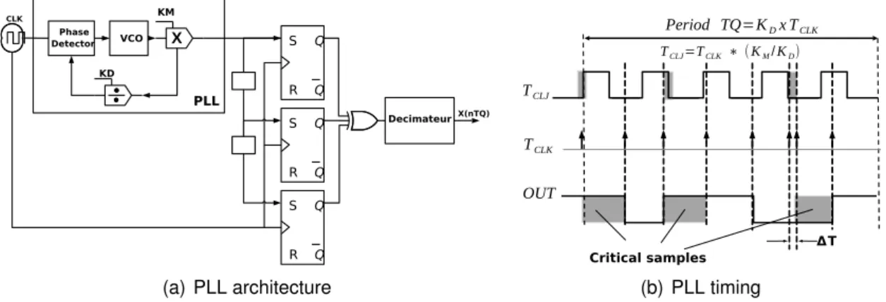
As stated previously, the old hardware manner to build such RNGs was to use a mechan-ical machine or a physmechan-ical phenomenon as entropy source, which can thus be based on noise [35], metastability (frequency instability [36]), semiconductor commercial or indus-trial component circuit (PLL [37], amplifier, filters [38], inverter,. . . ), or a variation in the CMOS/MEMS process technologies (transistor). In spite of the quality of the generated
randomness, most of these techniques are however, either slow processes (i.e,
extract-ing noise from a component) or costly (e.g., extracting or measuring noise may require
specific equipment like an oscilloscope). All these previous drawbacks are the motivation behind the development of hardware generators based on a software design. The latter consist of developing deterministic algorithms by targeting a specific hardware system, like a Field Programmable Gate Array (FPGA), before automatically deploying it on the hardware architecture by using ad hoc tools.
FPGA devices are reconfigurable hardware systems. They allow a rapid prototyping,i.e.,
explore a number of hardware solutions and select the best one in a shorter time [39].
The design methodology on FPGA relies on the use of a High Description Language
(i.e, Verilog, VHDL, or SystemC) and a synthesis tool. Because of this, FPGA has
be-come popular platforms for implementing random generators or complete cryptographic schemes, due to the possibility to achieve high-speed and high-quality generation of
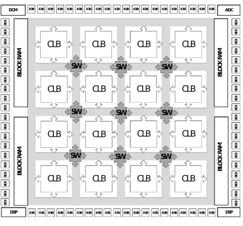
ran-dom. The general architecture of a FPGA presented in Figure 1.2 is based on LCA
(Logic Cell Array), which is composed of three parts, namely: Configurable Logic Block
(CLB) [40], Input Output Block(IOB), and interconnect switches. FPGA could
addition-ally include more complex components like aDigital Signal Processing(DSP), aRandom
Access Memory(RAM), aDigital Clock Manager(DCM), or anAnalog-Digital Converter
(ADC/DAC). The nomination of the internal blocks depends on the FPGA vendors (Xil-inx, Altera, Actel . . . ) even they have a similar functionality. The CLB structure is mainly based on Look-Up Tables (LUTs [41]), additionally with a Flip-Flop and some
multiplex-ers. A K-input LUT is a2K×1-bit memory array based on a truth table of K-bits inputs.
These later can executes any logic functions as XOR/ADD/SHIFT. . .
Different implementations of RNG on FPGA have diverse characteristics. First of all, does it provide true random or pseudorandom numbers? In the second reproducible case, which algorithm is implemented? The next characteristic is the way each block is deployed on the FPGA, namely by computing or in a hardware manner. For instance, for a polynomial division, there is a choice between look-up table in software and a hardware shift register. Furthermore, the quality of the FPGA model that implements a random number generator can be evaluated according to many criteria. In a statistical perspec-tive, the output has to be verified against some well-known test suite like the NIST [42], DieHARD [43], or TestU01 [44] ones. From the hardware perspective, one objective is to provide the highest frequency per randomly generated bit with less FPGA hardware resources (CLB, IOB, ...).
This chapter surveys a large set of selected hardware implementations of random number generators on FPGA. Both pseudorandom and true random generators are investigated, while linear and non-linear generators are discussed in the PRNG case. Each approach is explained in details, and a discussion on the choices of both implementations and generations are systematically given. Performance with respect to frequency, area size, weaknesses, and statistical evaluations are finally presented, when they are available.
The remainder of the chapter is as follows. Section1.2describes FPGA implementation
Figure 1.2: General structure of a FPGA by Xilinx
(CPRNG). The true random ones are detailed in Section1.4. Each of these three sections
ends by a FPGA implementations comparison regarding area resources and throughput
(see Section1.5). While, we recalls statistical batteries of tests and scores of some RNGs
on FPGA are provided in Section1.6. This chapter ends by a conclusion section, in which
the review is summarized and future investigative directions are outlined.
1.2/
L
INEARP
SEUDORANDOMN
UMBERG
ENERATORSThis section and the next one are devoted to pseudorandom number generators on FPGA. Recall that the latter are defined by a tuple containing a recurrent equation of
the form xt+1= f (xt). This recurrence may be linear or not. The linear case is investigated
in the current section, while the non-linear case is detailed in Section1.3.
Linear PRNGs are a special case of linear recurrence modulo 2. They are convenient
for low power and high speed requirement but, due to the limitation of the shift register
state (two possibilities: 0 and 1), the period of these generators is usually short.
Be-cause of this, many hardware optimizations are proposed to increase the period (they will be detailed thereafter). A linear PRNG of w bits can be defined by the following Equa-tions (1) [45]: xt+1= A × xt (a) yt = B × xt (b) rt = w P `=1y t `−12−`(c) (1)
Indeed the first equation (a) defines the function f , where xt = (xt
1.2. LINEAR PSEUDORANDOM NUMBER GENERATORS 23
the k-bit vector at step t (F2 is the finite field of cardinality 2 and S is the internal state
space of the generator). The other equations (b) and (c) define the function g, where
yt = (yt0, . . . , ytw−1) ∈ U = Fw2 is the w-bit output vector at step t, and U is the state space of the output. Additionally, A is a k × k transition matrix, B is a w × k output transformation matrix, which produces the output bits which corresponds to the internal RNG state, and
rt∈[0, 1] is the output at step t. All the elements of A and of B are in F2.
In the simplest case we have w = k and B is the identity matrix, which means that the
state bits are directly used as random output bits. In case where w < k, the output are either propagating in another circuit, or multiple state bits are XORed together to produce each output bit, as in the case of Mersenne Twister [46]. These linear generators are cov-ering Tausworthe or Linear Feedback Shift Register [47], polynomial Linear Congruential Generators [48], Generalized Feedback Shift Register (GFSR [49]), twisted GFSR [50], Mersenne Twister, linear cellular automaton, and combinations between them. More de-tails will be presented regarding each of these generators in this survey.
1.2.1/ LINEAR CONGRUENTIAL GENERATORS
Linear Congruential Generators (LCGs) [48] are founded on system of linear recurrence equations defined as:
xt+1= (axt+ b) mod 2k, (2)
where a (the “multiplier”), b (the “increment”), s.t. 0 ≤ a, b ≤ 2k−1 are parameters of the
generator,
This latter is often called aMultiplicative Congruential Generator[51] (MCG) if b= 0, and
Mixed Linear Congruential Generator, otherwise.
In [52], two optimized LCGs are proposed, namely the Ranq1 and Ran [53]. Ranq1 is
a MCG working modulo264, while its seed is produced by a64-bits right XORshift [54].
Let us first recall that the XORshift takes an input and iteratively executes an exclusive or (XOR) of the binary number with a bit shifted translation (left and right) of itself. The
second one, the Ran generator, combines a LCG generator with two XORshifts, and
the results are XORed by a Multiply with Carry (MWC) generator [55]. In MWC, the
equation (2) is modified as follows: the constant b is replaced by the carry bt which is
defined by b0, the initial carry, is less than a and bt+1= bax t+ bt
232 c.
Authors of [52] optimized the implementation of the64-bits constant coefficient multiplier
a × xt. However the64-bit multiplication is problematic due to DSP macro limitations that
support only 18-bit operations in Xilinx’s FPGA. This is why these authors proposed a
pipeline of multiplier-adder architecture, which takes 5 cycles for Ran and 4 for Ranq1,
while the output is the least significant 32 bits. Comparisons realized in their article
showed that these two new optimized implementations have a lower cost in the area than other PRNGs like the Mersenne Twister [46], which use memories or multiplier macros of the FPGA. But the authors were wrong when they assumed that the multiplication by a constant is similar to the multiplication by a variable. In the former (Oudjida et al [56–58]),
the multiplication is implemented in a multiplierless way, i.e., using only additions,
Authors of [59] have presented a coupling of two Coupling Linear Congruential
Genera-tors (CLCG), further denoted as CLCG-1 and CLCG-2. Each one generates a separate
output with different parameters described as follow: xt1+1= (a1xt1+ b1) mod 2k xt2+1= (a2xt2+ b2) mod 2k Ct1+1= ( 1 if xt+1 1 > xt2+1 0 otherwise. (3) xt3+1= (a3xt3+ b3) mod 2k xt4+1= (a4xt4+ b4) mod 2k C2t+1= ( 1 if xt+1 3 > xt4+1 0 otherwise. (4)
The first CLCG-1 of [59] is characterized by {xt+1
1 , xt2+1, C1t+1}while the second CLCG-2 is
defined with {x3t+1, xt4+1, C2t+1} (Ct1 and C2t are bit sequences). CLCG-2 aims at selecting
which bit must be taken from CLCG-1 as a final output yt: yt = Ct
1 if Ct2 = 0, otherwise
the bit Ct
1 is ignored. For instance, the authors assume a simple format of the multipliers:
a1 = a3= 2δ1+ 1 and a2= a4 = 2δ2 + 1, where 1 < δ1, δ2< k. Indeed, the new format of xt+1 1
for CLCG-1 (and similarly for x2, x3, and x4) is as follow:
xt1+1= ((2δ1 × xt
1 mod 2k)+ xt1+ b1) mod 2k, (5)
where2δ1 × xt is the result of shifting xt exactly δ
1 times to the left, and the modulation is
computed as the k least significant bits of what is in parentheses. However, a large value of k leads to a large latency. To solve this problem, an implementation of P stages of addition and comparison for the two CLCGs has been proposed in this article. It divides the k-bits numbers into P-pipeline parts, processes each k/P-bits part in a pipeline stage,
and finally generates1-bit of C1and C2simultaneously. Additionally, it takes the results of
each stage and sends them to both the previous and the next stages, in order to produce the current and the next outputs.
1.2.2/ LINEAR FEEDBACK SHIFTREGISTER GENERATORS
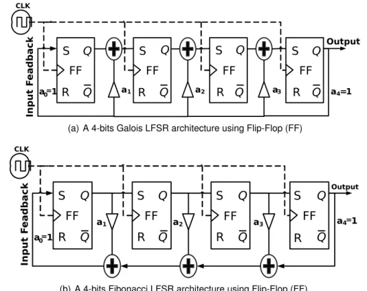
Linear Feedback Shift Register generators (LFSR) orTausworthe[47] are linear recurrent
generators. An LFSR uses a sequence of Flip-Flop (FF) as shift registers to generate one bit per iteration. Each register is connected to its neighborhoods, the binary value in each register is shifted at each iteration, while the last register produces the output (see
Figure 1.3). A XOR is operated on some designed registers to build a feeadback input
to the first register, which is expressed by a characteristic polynomial. As depicted in
Figure 1.3, two configurations are usually considered, namely the Galoisand Fibonacci
setups. These two aforementioned implementations are synchronized with a main clock (CLK), in which at each edge the maintained data (1-bit) in FF is released and a new
input is stored. The matrix A of Equation. (1) is in this case:
A= 0 Ik−1
ak ak−1, . . . , a1
!
. (6)
The characteristic polynomial of the matrix A is xt+1 = a
1xt+ · · · + akxt+1−k. In the above
equations, a1, . . . , ak represent the LFSR coefficients, each in F2. Accordingly, if any of
these coefficients exists, it deploys a XOR operand on the output (remark that the matrix
Bof Equation (1) is the identity matrix I).
Even though many FPGA implementations of such LFSRs can be found in the literature, only few of them are really optimized for this architecture. In [60], the authors present
1.2. LINEAR PSEUDORANDOM NUMBER GENERATORS 25
(a) A 4-bits Galois LFSR architecture using Flip-Flop (FF)
(b) A 4-bits Fibonacci LFSR architecture using Flip-Flop (FF)
Figure 1.3: A 4-bits linear feedback shift register generator with a feedback polynomial a0∗ X4+ a1∗ X3+ a2∗ X2+ a3∗ X+ a4(a0= a4 = 1).
of67 bits (LFSR-1 and LFSR-2). At each clock cycle, the SG directly takes the value of
the output bit which is generated by the second LFSR-2 if the output bit from the first
LFSR-1 is equal to 1; if not, both outputs are discarded. The second version, named
Alternating Step Generator(ASG), considers a third LFSR-3 of 141 bits in addition of the two previous ones. This latter is used to control which output bit will be taken from the two
first LFSRs of131/137-bits. For comparison purposes, if T1, T2, and T3 are the periods of
LFSR-1, LFSR-2, and LFSR-3 respectively, let us note that the SG has a total period of TS G = (2T1 −1) × (2T2 −1) (length ' 64 bits), while it is TAS G = 2T1(2T2 −1) × (2T3 −1) for
ASG (length '128 bits).
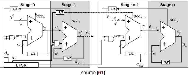
LFSR based Accumulator Generator proposed in [61] is a PRNG based onDigital
Sigma-Delta Modulator[62] made from accumulator circuits. This latter is used to divide the
fre-quency in aFractional-n Frequency Synthesizer[63]. Authors of [61] propose a pipeline
of N= 9 serial digital accumulators of w = 8 bits based FPGA as described in Figure1.4.
Each accumulator, which can produce M = 2w possible values, is a self-recursive
struc-ture based on quantization error mapping function formalized in Equation. (8), where
the accumulator’s feedback coefficients are time-varying, using another linear feedback
shift register. The accumulator, which is presented in Equation (7), is parameterized by
the input seed x0, the accumulator sum p, the carry output acc, the quantization error
e, and the feedback coefficients c = 2−w of the accumulators as outputs. The input of
each n= 0, . . . , (N − 1) stage during the processing uses the quantization error et−1 of the
previous stage. Therefore, the PRNG gives a better uniform outputs by propagating the
source [61]
Figure 1.4: Block-level model of a w-bit digital accumulator PRNG comprising n stages
is implemented with another accumulator. The latter are multiplied by a binary variable
dw ∈ {0, 1} of the LFSR to control the feedback depending on the period of LFSR. The final
output yt= e
outis the last generated etN−1evaluated in Equation (8).
ptn+1= x0+ et0+ acct1d0t, n= 0 etn−1+1 + etn+ acctn+1dtw−1+1, 0 < n < N − 1 etn−1+1 + etn, n= N − 1 (7)
etn+1= ptn+1 mod 2wand acctn = ( 1 pt n ≥ M 0 pt n < M (8)
1.2.3/ LOOK-UP TABLE OPTIMIZED GENERATORS
Look-up Table (LUT [41]) optimized generators use logic block as a digital component de-fined in a CLB provided by the FPGA vendors. It is used for implementing many function and operation generators for a hardware optimization purpose. A LUT consists of a block of RAM (Random Access Memory) implemented as a truth table that is indexed by the LUT inputs.
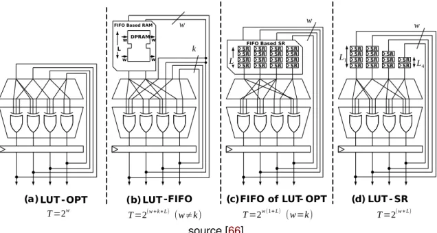
In [64–66], the authors present a series of LUT PRNGs based on F2 linear matrix
recur-sive algorithms (see Figure 1.5). The main idea is to produce a maximum efficiency at
area level. The authors associate either Flip-Flops (FF), Shift Registers (SR), or block of RAMs (RAM) with LUT to perform shift/multiplication operations in FPGA. However,
creating long period sequences T = 2w with this method is a difficult task. To solve this
problem, large optimized LUT based {FF, SR, RAM} pairs are investigated.
The first proposed PRNG is called LUT-OPT (LUT optimized, (a) in Figure1.5). It maps
each row of the recurrence matrix A as a XOR gate using just LUT and FF. To generate w
bits per cycle requires w LUT-FFs in a single LUT of k-bits during a period of T = 2wwhere
w = k (see Figure1.5). Their estimations of the FPGA resources conclude that even if
an application requires64 bits for each cycle, their implementations necessarily use 512
LUT-FFs to produce a period of 2512−1. The second one, the LUT-FIFO (b), is used to
1.2. LINEAR PSEUDORANDOM NUMBER GENERATORS 27
source [66]
Figure 1.5: LUT based shift-register and FIFO FPGA optimized PRNG: (a) maps each row of the recurrence matrix as a XOR gate using LUT-FF, (b) uses RAM block memory as k × k FIFO to store the recursive sequences, (c) loads the state in FIFO based shift-register SR instead of BRAM, (d) cascading of any number of Xilinx SRL32 to create a k-bit SR
block memory (dual-port RAM) of FPGA as L × k FIFO to store the recursive sequences. In this case, each new output bit is depending on one bit from the last iteration. They next
propose a FIFO based shift-register SR (c) with a fixed length L of1-bit, to load the w-bit
state in parallel instead of using dual-port RAM. They also propose a LUT-SR PRNG (d) that turns the use of LUT as a k-bit Shift-Register using “Xilinx SRL32”, with the length of
each “SR” varying as follows: 1 < Li< L. The “Xilinx SRL32”, allows the cascading of any
number up to32-bit shift registers to create a shift register with any size needed.
1.2.4/ TWISTED GENERALIZED FEEDBACK SHIFT REGISTER PRNG
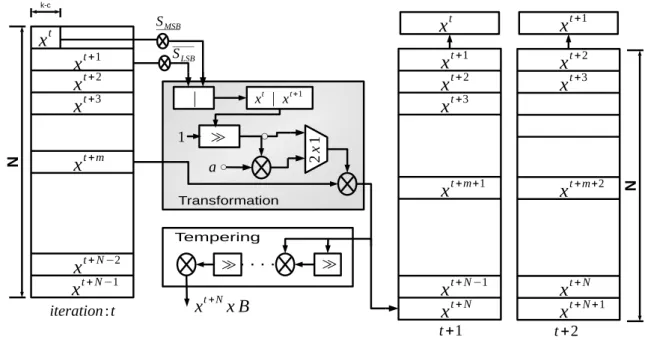
Twisted Generalized Feedback Shift Register (TGFSR) proposed in [50] is an extension of
Generalized Feedback Shift Register“GFSR” [49], which uses an array of shift registers to generate more than one bit for each state change. Therefore, a TGFSR is based
on recurrence of N sequences of words, x0, . . . , xN−1, each containing k-bits and two
parameters, namely a bitmask size c, such that c 6 k − 1 and a initial median position m
with1 ≤ m ≤ N.
TGFSR computes the t+ N-th word (t = 0, 1, . . . ) by operating with three words: the first
two words xt and xt+1with the median word xt+m. More precisely (see Figure1.6):
1. It computes the c least significant bits (LSB) of xt+1 and the k − c most significant
(MSB) ones of xt. These two vectors are obtained thanks to the two following
bit-mask vectors: Scfor(0, . . . , 0, 1, . . . , 1) and Sk−c for(1, . . . , 1, 0, . . . , 0). 2. These two vectors are further concatenated through(xt&S
Figure 1.6: Twisted Generalized Feedback Shift Register architecture: at each recurrence
operation t, it computes xt+N thanks to the three words xt, xt+1, and xt+m and generates
the output with tempering function
3. The result x0 is then "multiplied" with a matrix A, caracterized with values
(a0, a1, . . . , aw−1) as defined in Equation. (10).
4. The final results of the previous calculations are then XORed with the median word
xt+m.
By putting c= 0, then the Equation (9) represents the TGFSR PRNG [50], conversely it is
Mersenne Twister [46].
xt+N = xt+m⊕(((xt&Sk−c) | (xt+1&Sc)) × A), where (9)
x0× A= (
x0 1 if x00= 0
(x0 1) ⊕ (a
0, a1, . . . , aw−1) otherwise (10)
Consider c1 and c2 as given bitmasks and b1, b2, b3, and b4are constant integer
param-eters. At each iteration t, the value xt+N resulting of the recurrence Equation (9) serves
as input of the tempering module of the TGFSR. This step improves the equidistribution of the output. This step, which is described a sequence of bitwise/shift computation is
equivalent to a matrix product as formaized in Equation. (1)(b).
This one is defined in Equation (11) where c1, c2 (resp. b1, b2) are tempering bitmasks
(resp. bit shifts).
z= xt+N⊕(xt+N b 1), z= z ⊕ ((z b2)&c1), z= z ⊕ ((z b3)&c2), yt = z ⊕ (z b4). . (11)
1.2. LINEAR PSEUDORANDOM NUMBER GENERATORS 29
Mersenne Twister (MT) is proposed as a special case of TGFSR that has a long period
of2wN−c−1. To achieve this, the authors in [46] propose two MT configurations:
• “MT11213” with a period of 211213 −1 that has w = 32, N = 351, m = 175, c =
19, and a = 0xE4BD75F5 as recurrence parameters, and c1 = 0x655E5280, c2 =
0xFFD58000, b1= 11, b2= 7, b3= 15, and b4 = 17 for tempering ones
• “MT19937”, which has a period of 219937 −1, has w = 32, N = 624, m = 397, c =
31, and a = 0x9908B0DF as recurrence parameters, and c1 = 0x9D2C5680, c2 =
0xEFC60000, b1= 11, b2= 7, b3= 15, and b4 = 18] for Tempering ones.
Two FPGA implementations of Mersenne Twisters MT19937 and MT11213 are proposed
in [52] for Monte Carlo applications in finance. The authors implement many Block
RAM memory or namely “BRAM” for matrix multiplications: a single dual-port BRAM for MT11213 and two dual-port BRAM for MT19937. The RAM memory, configured in the read-before-write mode, operates like a feedback shift register. In this mode, the new inputs are stored in memory at appropriate write address, while the previous data are transferred to the output ports. This latter coming from BRAM are then processed
follow-ing the Equation (6). The same approach has been proposed in [67] for MT19937 using2
BRAM. Authors of [68], for their part, have implemented the MT11213 in three platforms for the sake of comparison, namely: FPGA, CPU, and GPU. Remark that, for testing the FPGA performances, initial and Tempering matrix parameters have been extracted from a PC software, due to the hardware cost consuming by the initialization stage of MT. How-ever, both transformation and Tempering modules are executed in FPGA. In this case, two dual-port BRAMs are necessary for the other stages. This structure reduces the area
compared to other MT implementations in FPGA, and the speed up is about ≈ 9× and
≈25× compared to GPU and CPU respectively.
In [69], the authors have proposed two parallel PRNG implementations with many levels of three different Mersenne Twisters: the MT19937-32bits, the MT19937-64bits, and the
SIMD-oriented Fast Mersenne TwisterSFMT19937 [70]. The first one is theInterleaved Parallelization(IP), that generates w-bits for each P memory block separately.
In the IP configuration, the N= 624-words state vector is located across multiple memory
banks of the same size. Each P memory bank has d input/output ports I/O of w-bits, while each I/O port generates v-bits per clock cycle every q read operation. Therefore,
the number of clock cycle τ required to generate a random number is equal to τ = (w ∗
(q+ 1))/v ∗ d. The second one is theChunked Parallelization(CP), that uses the output
bits of each RAM bank as the far recurrence input for the next RAM bank. Therefore, the N-words state vector is sequentially split into chunks across a number of banks of different size. Even though the IP version has a better throughput than the CP one, the latter uses lesser RAM blocks compared to the IP version (3 levels of CP use 2 BRAMs
while IP uses3).
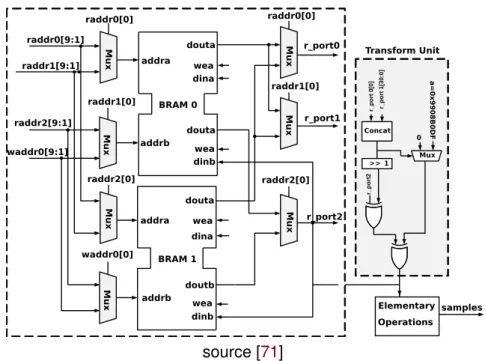
Authors of [71] give more hardware details for the deployment of RAM memories. Their
MT19937 implementation consists of a transform unit, a Temper Unit, a control unit
“Cross-bar" implemented using7 multiplexers, a 3R/1W RAM, and an address unit for RAM
ac-cess (3 read addresses and 1 address for writing). The main key of the latter is the
implementation of624 states of 32-bits register using BRAM memory of the FPGA (see
Figure 1.7). Therefore, instead of fetching the 3 state vectors using 3 BRAM as in [69],
source [71]
Figure 1.7: Mersenne Twister MT19937 architecture using 3R/1W BRAM: at each cycle,
R/W address is even address for BRAM0 and odd for BRAM1
write one. The R/W for the first BRAM operates with an even address, while the second R/W is in the odd address.
In [72], various degrees of parallelization of the MT19937 architecture (of degrees 2, 3, 4,
and 6) implemented in [71] and used for Monte-Carlo based simulations are proposed.
In this case, the configuration of BRAM is the key of the parallelism, where each degree
corresponds to the number of BRAM that are used (4 degrees= 4 implemented RAMs).
The authors use one 206 × 32-bit, two 207 × 32-bit dual-port BRAM, and four registers to
provide state consistency for the given parallelized states for 3 degrees as an example.
Here, all I/O ports of three BRAM are in read mode during initialization, while in the runtime just one is in read mode (the others being in write mode).
Finally, a recent FPGA implementation of Mersenne Twisters is presented in [73]. The
authors propose an alternative solution of the use of RAMs, which is named Circular
Buffer (CB). It is implemented for MT19937 (see Figure 1.8). The solution is based on
the fixed relationship between word indices. Words xt
j, x t
j+1, and x t
j+mwritten in the buffer
are passed to the transform unit. At each iteration, the first word xt
j is clocked out of the
buffer while new data xt+1
j is written to the free location. By this way, the linear recurrence
and the buffer of registers can be considered as a circular buffer. The linear recurrence is carried out by some combinational logic between the input and the output of the buffer. Therefore, the architecture is simplified since no logic operation for the table indices is needed.
1.2.5/ CELLULAR AUTOMATA BASED PRNGS
Cellular Automata (CA) is a discrete model, proposed by John von Neumann and Stan Ulam [74] as formal models of self-reproducing robots. The basic representation of one dimensional CA PRNG includes N cells with an internal state machine that can be a
1.2. LINEAR PSEUDORANDOM NUMBER GENERATORS 31
(a) BRAM configured as 3R/1W (b) Circular Buffer
source [73]
Figure 1.8: Different deployments of the linear recurrence (L.R) for Mersenne Twister PRNG: (a) using BRAM configured as 3R/1W, (b) using Circular Buffer of registers (L.R is linear recurrence of transferring function of MT)
Boolean function rule and k = 1-bit output as described in Equation (12). The latter
consider the function f : {0, 1}N → {0, 1} as the local transition rule, and the cells
neigh-borhood size N is2∗rd+1, where rd is the radius that represents the standard 1-D cellular
neighborhood. Therefore, at each iteration t, the CA structure can hold and update the
internal state for each cell, depending on the local rules and the states xt ∈ {0, 1} of their
neighborhoods j ( j = 1, . . . , N). There are 2N (rd = 1 and N = 3) states for a single CA
producing256 (28) possible rules classed by theWolframcode [75].
xtj+1= f (xtj−rd. . . xtj. . . xtj+rd) (12)
As an example, let us consider that N = 3, which leads to xtj+1 = f (xtj−1, xtj, xtj+1). The
184 rule updates the middle bit xt
j and then left shifts the input in the next iteration t as
follows: f(111) = 1, f (110) = 0, f (101) = 1, f (100) = 1, f (011) = 1, f (010) = 0, f (001) = 0,
f(000)= 0 (i.e. 11101011 → 101011).
Hybrid CA generator (HCA) is defined with more than one rule and can be integrated as a
state transition machine of2N/2 cycles between 2Nrules. Each transition cycle has a2×2N
length cycle. Two hybrid CAs are proposed in [76] as part of an encryption system. The first one is a PRNG of single state transition using rules90, defined by f (xt1, xt2, x3t)= xt1⊕xt3,
and 150, defined by f (xt
1, xt2, x3t) = xt1 ⊕ xt2⊕ xt3 to generate an encrypting real-time key
stream. The second one is a block cipher of two state transitions, each having 8 cycles
length with51/153/195 rules. The aim of this application is to use the first HCA to select
the transition sequences between rules used by each cell of the second HCA in the block cipher. The FPGA implementation of each CA is done with a logic combinational circuit (LCC) to define the rules. Then it uses LCG to control the loading operation of the CA and stores the data into a D flip-flop. Authors of [77], for their part, create an automatic software tool to generate the RTL code of any HCA configuration. Finally, in [78], authors increase the ratio of frequency/area and the security of their previous PRNG [77] by using a chain of HCAs instead of a single one.
Mixed CA generator is proposed in [79], where the author mixes the outputs of a37-bits
source [81]
Figure 1.9: Self-Programmable cellular automata generator: uses a super-rule90/156 to
dynamically determines when the rules have to change in each CA cell
drawbacks of this implementation are revealed during statistical evaluation, which can be surpassed only if the two PRNGs are clocked at different clock frequencies. This is why a new solution is presented in [80]. In this article, authors propose to XOR the last bit
of HCA with the last bit of LFSR to generate 1-bit per clock cycle. As a repercussion,
they found that the optimal combination for a PRNG of high quality is16-bits for CA with
a37-bits LFSR.
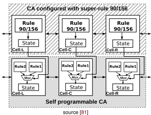
Self-Programmable CA (SPA) was presented first as a new rules for CA generator in [81]. The topological behavior of the generator proposed in [82] is the use of a super-rule 90/156 to dynamically determine when the rules have to change in each CA cell (see
Figure 1.9). In practice, the input rules of each neighbor cell are also a second CA
which is executed in parallel with the main cellular automata. Remark that, despite SPA gives a better throughput than the LFSR/HCA combination PRNG [80], it fails to pass the statistical tests of DIEhard battery.
Another cellular automata based PRNG is proposed in [83]. This latter combines a CA with a Non-LFSR (NSFR) generator based on A2U2 stream cipher design. Recall that the
stream cipher A2U2 [84] was presented as a new key cryptographic generator of 56-bits
for RFID tags application. It has a LFSR counter of 7-bits and two non-linear feedback
shift registers (NFSRs,17 and 9-bits). However, NFSR is known for its short period length.
Hence, their main contribution is to associate a CA PRNG of9-bits to increase the period
of NFSR, both having feedback between them (which means that the seed of NFSR is provided by CA and vise versa). This approach improves resistance to various forms of cryptanalysis like correlation attacks and algebraic ones. For the sake of completeness, notice that the authors of [85] have proposed a different implementation concept of the usual rules in CA. In their proposal, the initial state configuration of CA and its length depend on the current date.
1.3. NON-LINEAR PSEUDORANDOM NUMBER GENERATORS 33
1.3/
N
ON-L
INEARP
SEUDORANDOMN
UMBERG
ENERATORSChaotic generators (CPRNGs) are non-linear generators of the form x0∈ R: xt+1= f (xt),
where f is a chaotic map. They are attractive applications of the mathematical theory of chaos. Reasons explaining such an interest encompass their sensitivity to initial con-ditions, their unpredictability, and their ability of reciprocal synchronization [86]. From a cryptographer point of view, these chaotic PRNGs have major drawbacks often re-ported [9].
Chaotic Mapping PRNG are based on a polynomial mapping that uses a non-linear dynamic transformation, which is a quadratic mapping. Most of these generators are
based on the Logistic Chaotic Map called also “LCG” map [87], defined as follows:
xt+1 = α × xt(1 − xt), where 0 < xt+1 < 1 and α is the biotic potential (3.57 < α < 4.0).
The logistic map is mainly depending on the parameter α: its chaotic behavior is lost
when α is out of the range provided above. Moreover, if α > 4 and for almost all initial
values, the outputs diverge and leave the interval[0, 1]. The second most frequently used
function is the H´enon chaotic map [88], which takes a point (xt,yt) within the plan square
unit and maps it into a new point (xt+1, yt+1). This map is defined by these equations:
xt+1= 1 + yt− a(xt)2and yt+1= bxt, where a and b are calledcanonical parameters.
In [89], the authors have used fixed point representation [90] to implement the logistic map using Matlab DSP System Toolbox software. Fixed-point format is an approximation of real numbers, with much less precision and dynamique range than the floating-point format. Nevertheless, it has the merit of being very efficient in high-speed and low-power applications. This unit requires less power and cost to manipulate such kind of numbers than usual floating-point circuitry. They generate many designs with different lengths
from 16 to 64 bits, where the resources are depending on the precision (24 to 53 bits).
The multiplication is implemented with DSP blocks of FPGA that perform18x25 bits
mul-tiplications, while the multiplication by a constant α is a simple series of add and left-shift operations.
Authors of [91] compare the implementation of logistic map with the H´enon one. Unlike
the logistic map, the 64 bits multiplication in H´enon [88] map cannot be implemented
with a left shift operation, which leads to the use of DSPs blocks of the FPGA for all
multiplications needed to implement ax2. Two optimized versions of PRNGs based on
chaotic logistic map are proposed in [92], which aim to reduce resources and increase frequency, unlike in [89,91]. The first one is based on LUT and DSP blocks of the FPGA.
The second one rewrites the logistic map equation as follows: xt+1 = αxt −α(xt)2. The
objective of these two PRNGs is to pipeline the multiplication operations and synchronize them while adding some delays into each stage, in order to ensure a parallel execution
of sequences. The outputs are generated for each8-16 clock cycles and in each cycle a
new seed is inserted.
In [93], the authors vary the biotic potential α and observe the divergence of random
for almost all initial values. Accordingly, they propose a range of the form [α, 1 − α],
where thebiotic potentialis α <0.5. Another way to select the parameter α is presented
in [94]. They propose a couple of two logistic map PRNGs, each having different seed and
parameter (x0, α1and y0, α2respectively), where both generates pseudorandom numbers
synchronously. The main idea is to recycle the pseudorandom number generated by
the first chaotic map, namely xt+1, as the biotic potential α2 for the second one (yt+1)