Development of a MEMS Turbocharger and
Gas Turbine Engine
by
NICHOLAS SAVOULIDES
Bachelor of Science in Aeronautics and Astronautics, MIT, 1998 Master of Science in Aeronautics and Astronautics, MIT, 2000
Submitted to the Department of Aeronautics and Astronautics in partial fulfillment of the requirements for the degree of
Doctor of Philosophy
at the
Massachusetts Institute of Technology February 2004
@ Massachusetts Institute of Technology 2004. All rights reserved
I /
I-
)
A uthor I IC) Certified by MIASSACHUSETTS INS OF TECHNOLOGYLIBRARIES
AEiRO
Department of Aeronautics and AstronauticsJanuary 26, 2004 IL 14 -- I R.C. Maclaurin Certified by Certified by c ' Certified by_
Professor Alan H. Epstein Professor of Aeronautics and Astronautics, Committee Chairman
1) Professor S. Mark Spearing
Associate Pjdfssor ofAerogautics andstronautics
A. Waitz
K~ofqssor and Deputy Head of Aer hwiii and Astronautics
/4 'I 'I V A . ~ / Certified by Dr. Stuart A. Jacobson Research Engineer
Professor Edward M. Greitzer H. N. Slater Professor of Aeronautics and Astronautics Chair, Committee on Graduate Students
Development of a MEMS Turbocharger and
Gas Turbine Engine
by
NICHOLAS SAVOULIDES
Submitted to the Department of Aeronautics and Astronautics
on January 26, 2004, in partial fulfillment of the requirements for the degree of
Doctor of Philosophy
Abstract
As portable electronic devices proliferate (laptops, GPS, radios etc.), the demand for compact energy sources to power them increases. Primary (non-rechargeable) batteries now provide energy densities upwards of 180 W-hr/kg, secondary (rechargeable) batteries offer about 1/2 that level. Hydrocarbon fuels
have a chemical energy density of 13,000-14,000 W-hr/kg. A power source using hydrocarbon fuels with an electric power conversion efficiency of order 10% would be revolutionary. This promise has driven the development of the MIT micro gas turbine generator concept. The first engine design measures 23 x 23 x
0.3 mm and is fabricated from single crystal silicon using MEMS micro-fabrication techniques so as to
offer the promise of low cost in large production.
This thesis describes the development and testing of a MEMS turbocharger. This is a version of a simple cycle, single spool gas turbine engine with compressor and turbine flow paths separated for diagnostic purposes, intended for turbomachinery and rotordynamic development. The turbocharger design described herein was evolved from an earlier, unsuccessful design (Protz 2000) to satisfy rotordynamic and fabrication constraints. The turbochargers consist of a back-to-back centrifugal compressor and radial inflow turbine supported on gas bearings with a design rotating speed of 1.2 Mrpm. This design speed is many times the natural frequency of the radial bearing system. Primarily due to the exacting requirements of the micron scale bearings, these devices have proven very difficult to manufacture to design, with only six near specification units produced over the course of three years. Six proved to be a small number for this development program since these silicon devices are brittle and do not survive bearing crashes at speeds much above a few tens of thousands of rpm. The primary focus of this thesis has been the theoretical and empirical determination of strategies for the starting and acceleration of the turbocharger and engine and evolution of the design to that end.
Experiments identified phenomena governing rotordynamics, which were compared to model predictions. During these tests, the turbocharger reached 40% design speed (480,000 rpm). Rotordynamics were the limiting factor. The turbomachinery performance was characterized during these experiments. At 40% design speed, the compressor developed a pressure ratio of 1.21 at a flow rate of 0.13 g/s, values in agreement with CFD predictions. At this operating point the turbine pressure ratio was 1.7 with a flow rate of 0.26 g/s resulting in an overall spool efficiency of 19%.
To assess ignition strategies for the gas turbine, a lumped parameter model was developed to examine the transient behavior of the engine as dictated by the turbomachinery fluid mechanics, heat transfer, structural deformations from centrifugal and thermal loading and rotordynamics. The model shows that transients are dominated by three time constants - rotor inertial (104sec), rotor thermal (Isec), and static structure thermal (10sec). The model suggests that the engine requires modified bearing dimensions relative to the turbocharger and that it might be necessary to pre-heat the structure prior to ignition. Finally, the model suggests that the relatively large thermal mass of the combustor reduces the risk of compressor surge during the ignition transient.
Suggestions for future work include a re-design of the thrust bearing system, the addition of a functioning thrust balancing system, and improvement of the design used to introduce anisotropy to the journal bearing so as to reduce static torques acting on the rotor.
Thesis Supervisor: Alan H. Epstein
ACKNOWLEDGMENTS
First and foremost I would like to thank my fiancee, Rhea Kollias, for having stood by me throughout all of this effort. Her encouragement, affection, and mere presence proved to be invaluable to me. Next are my parents and the rest of my family who have always supported me in every possible way. I truly and deeply thank you all.
I would also like to greatly thank Prof. Alan Epstein, for having mentored me
through all my research and for his willingness to spend time talking about any issue almost whenever I knocked on his office door. Of course I would also like to thank the rest of my committee, Prof. Mark Spearing, Prof. Ian Waitz and especially Dr. Stuart Jacobson who was essentially a second advisor to me.
Outside of my committee I would like to thank Prof. Zoltan Spakovszky for his interest, time, and help as well as Dr. Frederique Ehrich who rarely failed to challenge my ideas. From the students, I would like to especially thank Chiang Juay Teo who spent endless hours with me testing devices and processing data. Thanks! I would also like to thank Lixian Liu for having run a multitude of simulations to help with my work. Finally, I would like to thank Bobby Sirakov and Yifang Gong who helped me with any
CFD calculations and Chris Spadaccini who helped me understand the details of the
operation of the micro-combustor as well as provide me with valuable data.
Fabrication of the turbocharger relied on a great team whose members worked extensive hours to deliver what was asked for. I would like to make special note of Li Wang, Hanqing Li, Ravi Khanna, and Dennis Ward. Essential to this work was also the support from a long list of staff including Viktor Dubrowski, Jack Costa, James Letendre, Paul Warren, Lori Martinez, Diana Park, Mary McDavitt, Susan Parker, Holly Anderson, Julie Finn and Marie Stuppard. I would like to thank you all for having made my stay here a more pleasant one.
Finally I would like to thank all of the faculty, staff, and students at the GTL for having made this a fun and rewarding experience, making special note of Chris Protz, and Chris Spadaccini with whom I shared many laughs and memories.
This research was supported by the Army Research Office and the Army Research Laboratory Collaborative Technology Alliance. This support is gratefully acknowledged.
I dedicate this work to my beloved grandfather, Theofilos Savoulides (1999). He will always live in my memory as a paradigm...
CONTENTS
CHAP TER ... 21
Introdu ction ... 2 1 1.1 Background ... 21
1.2 Demo Engine Research... 22
1.3 Objectives and Approach... 27
1.4 Applications of Research... 28
1.5 Previous Work ... 29
1.5.1 Systems Integration... 29
1.5.2 Thermal, Structural, and Materials Design... 30
1.5.3 Combustion... 31
1.5.4 Turbomachinery and Fluid Dynamics ... 31
1.5.5 Bearing Design and Rotor Dynamics ... 32
1.5.6 Electrical Machinery ... 33
1.5.7 Fabrication and Packaging ... 33
1.6 Literature Review... 34
1.6.1 MEMS Gas Turbine Engine - Tohoku University (Japan) ... 34
1.6.2 Micromachined Gas Turbine Generator- IHI and Tohoku University... 34
1.6.3 Micromachined Gas Turbine - Stanford CA and Honda Japan ... 35
1.6.4 Ultra Micro Gas Turbines - University of Tokyo ... 36
1.6.5 MEMS Rotary Engine - UC, Berkeley... 36
1.6.6 MEMS Free-Piston Knock Engine - Honeywell... 38
1.6.7 Other Projects... 39
1.6.8 Advantages / Disadvantages of Other Approaches... 39
1.7 Organization of Thesis... 39
1.8 R eferences... 4 1 CHAP TER 2 ... 51
Engine Design Evolution and Fabrication... 51
2.1 Fabricated Devices... 51
2.2 Turbocharger Layout ... 52
2.3 Fabrication ... 55
2.3.1 Constraints ... 56
2.3.2 Special Fabrication Processes ... 57
2.3.3 Manufacturing Yield... 63
2.4 Design Evolution ... 65
2.4.1 Initial Design ... 65
2.4.2 t Re-Design (Builds A, B and C)...67
2.4.3 2 d Re-Design (Build D , D3, 4)...69
2.5 Sum m ary ... 90
2.6 References... 90
C H A P T E R 3 ... 93
Rotordynam ics - A nalysis and D esign... 93
3.1 Engine Rotordynam ics Overview ... 93
3.1.1 Thrust Bearings... 95
3.1.2 Journal Bearings... 97
3.2 Journal Bearing D esign M ethodology ... 106
3.2.1 Single Bearing D esign ... 106
3.2.2 A nisotropy... 112
3.2.3 Dual Bearings... 113
3.2.4 Design Implementation and Rotor Deformations... 114
3.3 Assessment of Static/Dynamic Journal and Seal Geometries... 119
3.3.1 Evaluating Effects of Com pressibility ... 120
3.3.2 Static Seal and Journal Flow Model Results... 122
3.3.3 Dynam ic A xial Eccentricity M odel ... 125
3.4 Isotropic/A nisotropic Stiffness M odels ... 127
3.4.1 Isotropic Stiffness M odel... 128
3.4.2 A nisotropic Stiffness M odels... 130
3.5 Rotor M om ents ... 138
3.5.1 M ask A lignm ent... 138
3.5.2 Bond A lignm ent... 138
3.5.3 Etch U niform ity ... 139
3.5.4 Im balance M odel ... 142
3.5.5 Principle A xis M odel... 147
3.6 A ssessm ent of Rotor M om ents ... 149
3.6.1 Fabrication M easurem ents... 150
3.6.2 Fiber D ata M easurem ents ... 150
3.7 Sum m ary ... 151
3.8 References... 152
C H A P T E R 4 ... 155
Experim ental Setup... 155
4.1 G as H andling System and Instrum entation... 155
4.2 D ata A cquisition System ... 159
4.3 References... 159
C H A P T E R 5 ... 161
Testing - Rotordynam ics... 161
5.1 A ssessm ent of D evice G eom etries... 161
5.1.1 Thrust Bearing G eom etry ... 162
5.1.2 Journal Bearing and Seal G eom etry ... 165
5.2 Testing Procedure - Spinning for the 1st Tim e ... 168
5.3 A ssessm ent of Rotordynam ic Stiffnesses ... 169
5.3.2 Axial Stiffness... 175
5.4 A ssessm ent of Rotor M om ents ... 177
5.4.1 1st M om ents... 177
5.4.2 A xial-Radial Coupling -2"d M om ents... 178
5.5 Rotordynam ic Stability Phenom ena ... 179
5.5.1 Radial Instability ... 179
5.5.2 Axial Instability ... 179
5.5.3 Sum m ary of Crashes... 181
5.6 Sum m ary ... 182
5.7 References... 182
C H A P T E R 6 ... 183
Testing -Turbom achinery... 183
6.1 High Speed Challenges... 183
6.2 Test Procedure ... 185
6.3 H igh Speed D ata ... 189
6.4 H igh Speed D ata Analysis ... 194
6.5 Sum m ary ... 198
C H A P T E R 7 ... 201
D em o Engine Startup Transient M odeling ... 201
7.1 Ignition Setup and Operational Overview ... 201
7.2 A ssum ptions and Boundary Conditions... 202
7.3 Cold Flow ... 203
7.3.1 Com pressor M ap... 204
7.3.2 Turbine M ap... 205
7.3.3 Cold Flow Equilibrium Running Point... 206
7.4 Ignition Transient... 207
7.4.1 Therm al Analysis... 208
7.4.2 Rotor Inertia... 218
7.4.3 Structural Deform ations... 219
7.4.4 Rotordynam ics ... 220
7.5 M odel Validation ... 221
7.5.1 A ngular A cceleration... 221
7.5.2 Com bustion... 224
7.6 Results and Ignition Acceleration Strategies ... 226
7.6.1 Sim ulation 1 -Baseline... 226
7.6.2 Sim ulation 2 - Baseline + Clearance V ariation... 235
7.6.3 Sim ulation 3 - Baseline + Device Pre-Heating ... 239
7.6.4 Simulation 4 -Baseline + Thermally Isolated Compressor... 243
7.6.5 Other Strategies... 247
7.7 Sum m ary ... 247
7.8 References... 249
C H A P TE R 8 ... 251
8.1 Rotordynam ic Design Space... 251
8.2 Radial-A xial Coupling ... 254
8.3 Suggested Rotordynam ic D esign Changes ... 256
8.3.1 Thrust Bearings... 256
8.3.2 Journal Bearing ... 257
8.3.3 A nisotropy System ... 258
8.3.4 Thrust Balance System ... 259
8.4 Sum m ary ... 259 8.5 References... 260 C H A P T E R 9 ... 261 Conclusion ... 261 9.1 Sum m ary ... 261 9.2 Contributions... 262 9.3 Future W ork ... 263 A P P E N D IX ... 265
Journal/Seal Flow M odel... 265
A .1 Incom pressible ... 265
A .2 Isotherm al Com pressible ... 266
A .3 M odel Com parison... 270
A .3.1 Flow Com parision... 271
A .3.2 Force Com parison... 272
A P P E N D IX B ... 275
Anisotropic Stiffness M odel ... 275
A P P E N D IX C ... 279
Packaging... 279
C.1 Cold Flow Packaging... 281
C.2 H ot Flow Packaging... 282
C.3 Com bustion Flow Packaging ... 284
A P P E N D IX D ... 291
U ncertainty Analysis... 291
D .1 U ncertainty of the Independent M easurem ents ... 291
D .1.1 Pressure ... 291
D .1.2 M ass Flow Rate... 292
D .1.3 Speed... 292
D .2 U ncertainty of D erived Quantities... 293
D .2.1 Bearing Clearance... 293
D .2.2 Thrust Bearing N ozzle Diam eters... 294
D .2.3 Com pressor Rotor Inlet Flow Rate ... 294
D .2.4 Com pressor Pressure Ratio ... 295
D .2.5 Turbine Pressure Ratio (Reciprocal)... 295
A P P E N D IX E ... 297
Parasitic Pow er Loss M odel... 297
A P P E N D IX F ... 301
Com pressor M ap Interpolation ... 301
C H A P T E R G ... 305
LIST OF FIGURES
Figure 1-1: a) Baseline Engine including generator, with compressor and turbine... 24
Figure 1-2: 3-D Schematic of Demo Engine (courtesy Diana Park)... 24
Figure 1-3: The turbocharger is built by etching two dimensional features ... 26
Figure 1-4: The turbocharger is built by bonding six wafers... 26
Figure 1-5: (a) Top view of real engine and compressor... 27
Figure 1-6: Steel 13mm diameter rotor rotary engine. (Courtesy Femandez-Pello)... 37
Figure 1-7: Components of the Imm MEMS rotary engine... 37
Figure 1-8: Honeywell knock engine... 38
Figure 2-1: Turbocharger cross section indicating main components ... 53
Figure 2-2: Schematic of the bearing system of the turbocharger... 54
Figure 2-3: Demo Engine: Identical to the turbocharger with the exception ... 54
Figure 2-4: Turbocharger pressure tap locations ... 55
Figure 2-5: Etch non-uniform ity... 57
Figure 2-6: Narrow and large feature etching... 58
Figure 2-7: Two masking materials can be used to etch overlaid features... 59
Figure 2-8: Stand alone bearing etch process. ... 60
Figure 2-9: Compressor bearing fabrication process... 62
Figure 2-10: Oxide pad rotor release scheme ... 63
Figure 2-11: Timeline of devices delivered by fabrication team... 64
Figure 2-12: Initial design of the turbocharger... 66
Figure 2-13: 1st R e-D esign... 67
Figure 2-14: 2nd R e-D esign... 70
Figure 2-15: Hydrostatic journal supply resistor network model... 73
Figure 2-16: Pressure drops in hydrostatic supply system... 75
Figure 2-17: 0-Ring force per unit length for varying cross sectional area. ... 77
Figure 2-18: Deflection at center of device due to 0-Ring compressive force ... 78
Figure 2-19: Effect of center O-Ring on thrust bearing flow rate. ... 79
Figure 2-20: Bond alignment feature... 81
Figure 2-21: 1st Turbine blade design change... 82
Figure 2-22: B uild Locos 4 ... 83
Figure 2-23: Compressor blade and fiber optic tab re-design... 85
Figure 2-24: Rotor deformation schematic due to centrifugal loading... 86
Figure 2-25: (a) Variation of seal clearance with speed. ... 88
Figure 2-26: 2"d Turbine blade design change... 89
Figure 3-1: 3D schematic of turbocharger rotor ... 94
Figure 3-2: Hydrostatic thrust bearing operation... 96
Figure 3-4: Hydrostatic journal bearing operation... 99
Figure 3-5: Jeffcott rotor... 100
Figure 3-6: Example of amplitude of journal's center precession from bearing center. 102 Figure 3-7: Effect of natural frequency on precession amplitude... 103
Figure 3-8: Objects want to spin about principal axes... 105
Figure 3-9: Relation between bearing clearance and length... 107
Figure 3-10: Stability boundary for a 330 ptm long compressor bearing... 108
Figure 3-11: Compressor bearing design chart... 109
Figure 3-12: Effect of imbalance on the compressor bearing clearance tolerance... 111
Figure 3-13: Anisotropic journal bearing ... 112
Figure 3-14: Effect of anisotropy on stability boundary... 113
Figure 3-15: Cross section of (a) single compressor bearing design... 115
Figure 3-16: Finite element analysis of the rotor structural deformation... 116
Figure 3-17: Rotor tip axial and radial deflections ... 117
Figure 3-18: Stability boundary for a single compressor bearing... 118
Figure 3-19: Mass flow rate comparison between incompressible and compressible.... 120
Figure 3-20: Pressure profile along a bearing with no entrance loss... 121
Figure 3-21: Force acting on bearing wall with no entrance loss... 121
Figure 3-22: Compressor bearing flow rate... 123
Figure 3-23: Turbine bearing flow rate... 124
Figure 3-24: Seal flow rates for seal which reduces flow entering turbine gap ... 125
Figure 3-25: Flow resistance network for computation of rotor axial position ... 126
Figure 3-26: Flow model used to determine the axial position of rotor.. ... 127
Figure 3-27: Stiffness of a 16x330 pm compressor bearing... 128
Figure 3-28: Natural frequency of a 16x330 pm compressor bearing... 129
Figure 3-29: Anisotropy Designs A, B, C, and D... 132
Figure 3-30: Stiffness anisotropy for design A... 133
Figure 3-31: Stiffness anisotropy for design B ... 134
Figure 3-32: Resistance network for anisotropic bearing ... 135
Figure 3-33: Natural frequency for anisotropic single compressor bearing... 136
Figure 3-34: Effect of plenum height on single compressor bearing device anisotropy. 137 Figure 3-35: Blade depth measurement locations for old compressor design... 139
Figure 3-36: Circumferential blade depth measurements for a single compressor. ... 140
Figure 3-37: Amplitude of sinusoidal blade depth measurements... 141
Figure 3-3 8: Imbalance contributions from each of the four sources... 146
Figure 3-39: Angle between rotor principal axis and rotor perpendicular... 149
Figure 3-40: Fiber optic eccentricity measurement schematic. ... 151
Figure 4-1: Turbocharger flow path setup ... 156
Figure 4-2: G as handling system . ... 157
Figure 4-3: Fiber optic operation schematic ... 158
Figure 5-1: Static flow test results example for the front thrust bearing... 163
Figure 5-2: Thrust Bearing "S-Curves" for the entire build C... 165
Figure 5-3: Static flow test results example for the turbine bearing... 166
Figure 5-5: Measurement of journal natural based on fiber data... 171
Figure 5-6: Summary of Build C turbine bearing natural frequency... 172
Figure 5-7: Single compressor journal bearing natural frequencies. ... 173
Figure 5-8: Fiber data taken showing that the anisotropic compressor bearing. ... 174
Figure 5-9: Extended single turbine journal bearing natural frequency. ... 175
Figure 5-10: Thrust bearing natural frequency ... 176
Figure 5-11: Thrust bearing flow rates decreasing with increasing speed... 178
Figure 5-12: Thrust bearing instability. ... 180
Figure 6-1: Rotordynamic acceleration map... 187
Figure 6-2: Thrust bearing flow rate changes during an increase in... 188
Figure 6-3: Summary of high speed data. ... 192
Figure 6-4: Spool overall efficiency. ... 195
Figure 6-5: Turbine/compressor efficiency relation ... 197
Figure 6-6: Power distribution in turbocharger. ... 198
Figure 7-1: Interpolation scheme example results... 205
Figure 7-2: Turbine map based on experimental results... 206
Figure 7-3: Engine Station definitions... 208
Figure 7-4: Static structure thermal model ... 209
Figure 7-5: Rotor 1 -D finite element model. ... 215
Figure 7-6: Spindow n test... 223
Figure 7-7: Combustor experimental results overlaid with the model predictions... 225
Figure 7-8: Simulation 1 -Compressor map(s). ... 228
Figure 7-9: Simulation 1 -Turbine flow rate... 228
Figure 7-10: Simulation 1 -Temperatures... 229
Figure 7-11: Simulation 1 -Rotor heat flux... 229
Figure 7-12: Simulation 1 -Static structure heat flux... 230
Figure 7-13: Simulation 1 -Bearing clearance ... 230
Figure 7-14: Simulation 1 -Speed, stability boundary, and natural frequency ... 231
Figure 7-15: Simulation 2 -Nominal Bearing Clearance 16 pm... 236
Figure 7-16: Simulation 2 -Nominal Bearing Clearance 17 pm... 237
Figure 7-17: Simulation 2 -Nominal Bearing Clearance 18 pm... 238
Figure 7-18: Simulation 2 -Nominal Bearing Clearance 17.5 pm... 239
Figure 7-19: Simulation 3 (Co = 17 pm) -Compressor map(s)... 241
Figure 7-20: Simulation 3 (C0 = 17 pm) -Temperatures ... 241
Figure 7-21: Simulation 3 (C0, 17 pm) - Bearing Clearance ... 242
Figure 7-22: Simulation 3 (Co 17 pm) - Speed/Stability ... 242
Figure 7-23: Simulation 4 - Compressor map operating line... 244
Figure 7-24: Simulation 4 -Temperatures... 245
Figure 7-25: Simulation 4 - Bearing Clearance ... 245
Figure 7-26: Simulation 4 - Speed/Stability... 246
Figure 8-1: Turbocharger constraints imposed by fabrication tolerances. ... 252
Figure A-1: Figure A-2: Figure A-3: Figure A-4: Figure A-5: Figure B-1: Figure B-2: Figure Figure Figure Figure Figure Figure Figure Figure C-1: C-2: C-3: C-4: C-5: C-6: C-7: C-8:
Schematic of isothermal compressible flow between two flat plates ... 266
Mass flow rate comparison ... 271
Numerical procedure followed to compute pressure along the duct... 273
Pressure profile along a bearing with no entrance loss ... 273
Force acting on bearing wall with no entrance loss ... 274
Total flow rate through each node in the circumferential direction... 276
Pressure at each node. ... 277
Turbocharger layout. ... 279
Turbocharger cold package. ... 281
Turbocharger hot package (external electrically heated air)... 283
Thermocouple plug for hot package... 284
Glass bead package schematic ... 285
Glass bead packaged turbocharger... 286
C om bustion package ... 288
Vacuum control system for combustion package... 289
Figure E-1: Thrust bearing power loss modeled as Couette flow... 297
Figure E-2: Parasitic power loss breakdown. ... 300
Figure F-1: CFD compressor map for 220 pm blade span (Sirakov)... 301
Figure F-2: CFD compressor stage efficiency for 220 pm blade span (Sirakov)... 302
LIST OF TABLES
Table 2-1: 1st Re-Design Changes ... 68
Table 2-2: 2"d Re-Design Changes ... 71
Table 2-3: Hydrostatic supply line pressure drop model (at 0.039 g/s -2000sccm)... 74
Table 2-4: Extrapolation of force per unit length for 0.406mm (0.016inch) O-Ring... 77
Table 2-5: Calculated performance of original and improved turbine designs ... 82
Table 2-6: 3rd Re-D esign Changes... 84
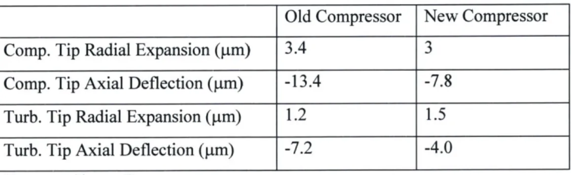
Table 2-7: Performance of original and improved compressor designs ... 86
Table 2-8: Rotor deformations based on both compressor blade designs ... 86
Table 3-1: Thrust bearing design... 96
Table 3-2: Typical values of parameters (single compressor bearing design)... 103
Table 3-3: Optimal bearing geometries (with no deformations) ... 110
Table 3-4: Journal Bearing Design (including deformations) ... 119
Table 3-5: Imbalance introduce by plane-like etch non-uniformity ... 142
Table 3-6: Imbalance model for turbine bearing device... 143
Table 3-7: Predicted levels of imbalance based on fabrication capability estimates... 144
Table 3-8: Imbalance model for compressor bearing device... 145
Table 3-9: Predicted levels of imbalance based on fabrication capability estimates... 145
Table 5-1: Thrust bearing geometry example -Build L4, Die 2 ... 164
Table 5-2: Journal bearing geometry example -Build C, Die 8... 167
T able 5-3: Seal G eom etry ... 168
Table 5-4: Measured Imbalance of devices ... 177
Table 5-5: Stability boundary predictions for turbine bearing devices... 181
Table 6-1: Summary of high speed devices... 189
Table 7-1: Natural convection parameters... 212
Table 7-2: Conduction param eters... 213
T able 7-3: Silicon properties... 215
Table 7-4: Spindown Test Comparison with Model... 223
Table 7-5: Baseline simulation parameters... 226
Table 7-6: Sim ulation 2 param eters... 235
Table 7-7: Sim ulation 3 param eters... 240
Table 7-8: Sim ulation 4 param eters... 244
Table 8-1: Tilt Angle Due to Etch Variations of Hydrostatic Plenum (@ 6.9 kPa)... 255
Table C-1: Turbocharger layout connection ports... 280
Table D-1: Pressure Transducer Uncertainty... 292
Table D-2: Mass Flow Meter Uncertainty ... 292
Table D-3: Journal Bearing Clearance Uncertainty... 294
Table D-4: Thrust Bearing Nozzle Diameter Uncertainty ... 294
Table D-5: Turbine Pressure Ratio Uncertainty ... 295
Table D-6: Compressor Fluidic Power Uncertainty ... 296
Table D-7: Turbine Fluidic Power Uncertainty ... 296
NOMENCLATURE
Roman
A area
Bi biot number
c damping, specific heat capacity of silicon
C journal bearing clearance
C, specific heat at constant pressure
Dh hydraulic diameter
E imbalance (mg-um)
e imbalance (um)
f moody friction factor (darcy friction factor) ffan fanning friction factor (f / 4)
Fo fourier number
h clearance
I rotor moment of inertia
Imb imbalance divided by rotor mass (um)
imb imbalance (mg-um)
k stiffness, thermal conductivity
L length
m rotor mass
ms static structure mass
m mass flow rate
M mach number
P perimeter, power
p static pressure
Q
heat flux (watts) r radius R gas constant (C, - CV) Re reynolds number t time T static temperature Tt total temperature U velocityGreek
ac principal axis angle w.r.t. geometric axial axis, thermal diffusivity thermal expansion coefficient
y ratio of specific heat at constant pressure and constant volume
c eccentricity ratio
journal bearing damping ratio
Tispool spool efficiency
p viscosity
TE pressure ratio ( Ptn+1 / Pt,)
p density
aY steffan boltzmann constant
torque, shear stress
Co angular speed
CHAPTER 1
INTRODUCTION
As electrical devices proliferate and become a part of ever day life for personal and military use (cell phones, laptops, GPS, radios etc.) the capability of conventional batteries to supply the requisite long duration energy and power to drive these devices is being sorely pressed. Primary (non-rechargeable) batteries can provide energy densities upwards of 180 W-hr/kg at reasonable power levels, but these batteries are expensive and contain hazardous waste. Secondary (rechargeable) batteries provide about half the energy density of primary batteries. Imagine the potential of a portable power source which has well over five times the energy density of today's best primary batteries. Hydrocarbon fuels have a chemical energy density of 13,000-14,000 W-hr/kg. A power source using hydrocarbon fuels with an electric power conversion efficiency of 10% would be revolutionary. This concept has driven the development of Power MEMS and the MIT microengine program.
This chapter will first introduce the mircroengine concept, giving a background discussion followed by an overview of the project. The objectives of this research as well as possible applications of microengines shall then be discussed. As this project has been ongoing for almost ten years some time will be spent presenting previous work done along with an extensive list of references. Finally, a literature review of similar research in Power MEMS will be presented.
1.1 Background
In 1994, Epstein et al. [1] proposed the concept of a MEMS (micro electro-mechanical systems) centimeter-scale gas turbine engine that would be manufactured using micro-fabrication techniques. This idea led to the creation of a multidisciplinary research program that currently employs about forty students, staff, and faculty. The device was to be made of silicon/silicon-carbide and was designed to operate based on a
Brayton cycle, just like conventional gas turbine engines. Successful creation of the device would rely on the development of high precision micro-fabrication techniques, speed turbomachinery, speed gas bearings, compact combustion systems, high-power micro electrical generators, high-temperature micro-scale packaging, high performance structures, and advanced materials. Possible applications considered at the inception of the program included propulsion, electrical power generation, motor-driven compressors for fluidic pumping and pressurization, micro-coolers for microchip cooling, and micro-rockets for small scale space propulsion [2,3,4,5,6,7]. Later the project focus shifted to electrical power generation and micro-rockets. This thesis will focus entirely on the gas turbine engine suitable for the electrical power generation application.
Even at a conventional scale, aircraft gas turbine engine design is challenging due to the fact that it consists of highly stressed high speed rotating components which are exposed to high temperature gases, must operate reliably and must be very light so as to be of any value for an aircraft. Fluid dynamic, thermodynamic, and structural concerns must be satisfied simultaneously for every component. In addition, all the secondary components such as the ignition system, secondary flow systems, starter motor, and electrical generator must be able to reliably operate at elevated temperatures.
Micro electro-mechanical systems are also highly interdisciplinary. Most MEMS devices rely on structural analysis, packaging design, circuit design, controls design, and fabrication process design. This makes a MEMS device challenging to build, usually requiring the effort of many people with different skills.
The microengine relies on both gas turbine engine design theory as well as MEMS design. This has led to the creation of a large team which occupies students, staff, and faculty from a large array of fields, which is split into several groups, each of which deals with a separate problem while retaining compatibility with each others work.
1.2 Demo Engine Research
The original idea conceived by Epstein was to build a micro gas turbine generator. The baseline design consisted of a single stage rotating spool with an integrated combustor and electrical generator. Efforts initially focused on building and testing a demo gas turbine engine and an electrical generator separately. Furthermore, the demo
engine development focused on two separate devices: a combustor and a turbocharger. The combustor retains all the features of the demo engine but does not have a rotating spool. The objective of this device is to characterize and determine the feasibility of combustion at the micro level and assess the thermal integrity of the design. The turbocharger is nearly identical to the desired demo engine, including a rotating spool and a combustor, it only differs in that the flow path of the compressor is separated from that of the turbine. The objective of this device is to characterize the performance of the turbomachinery, and test the rotordynamics. To further test the rotordynamics of the device a bearing device was also built and tested. This device consisted of just a turbine supported by a bearing system that was similar to the one in the engine. This thesis will focus entirely on the turbocharger and gas turbine engine. Figure 1-1 depicts the original baseline design, the demo engine design and the turbocharger design. Figure 1-2 is a 3-D schematic of the demo-engine.
Starter/
Co.mnrQe.nr Generator Fuel Diffuser Rotor
Vanes Blades Inlet
Fuel Manifold
Combustion Exhaust Chamber Nozzle
Turbine Turbine Rotor Nozzle Centerline Blades Vanes of Rotation
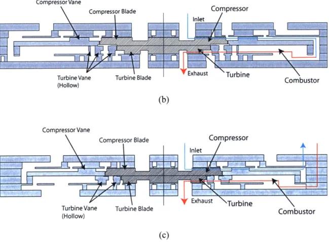
Compressor Vane
Compressor Blade Compressor
Turbine Vane Turbine Blade Ehaust Turbinembustor
(Hollow) (b) Compressor Vane Compressor Blade
IIle
Turbine Vane (Hollow) Compressort
I
haut BurbineTurbine Blade Combustor
(c)
Figure 1-1: a) Baseline Engine including generator, with compressor and turbine separated by a shaft. b) Demo Engine (removed generator and shaft). c) Turbocharger (separated compressor and turbine flow paths, but retains capability to run as an engine
by externally connecting flow paths of compressor and turbine).
Figure 1-2: 3-D Schematic of Demo Engine (courtesy Diana Park) Inlet
The current turbocharger measures 23x23x2.9 mm and is made entirely of silicon. It consists of an 8 mm diameter compressor and a 6 mm diameter turbine that spin at 1.2 million rpm. Integrated in the device is a combustor which encircles the turbine. The airfoil spans for both the turbine and compressor are 210 pim. Once testing of the turbocharger has been completed, engines with the compressor flow path connected to the turbine flow path will be assembled. Design operating conditions for these devices call for a combustor exit temperature of 1600 K a compressor pressure ratio of 2 with an adiabatic efficiency of 65%, a mass flow rate of 0.55g/s and are expected to have a marginally closed cycle. The blade spans would also have to be increased to 400 ptm. With some additional improvements to the design, an overall (chemical to electrical) conversion efficiency of order 5-10% is expected.
The turbocharger is fabricated using MEMS semiconductor microfabrication techniques. Each engine is assembled from six 100 mm diameter single-crystal wafers that are etched to define features and then bonded together to form complete engines. Each wafer corresponds to one or more engine components. The bonded set of wafers is then cut into four individual engines (called 'dies'). Figure 1-3 and Figure 1-4 depict the assembly process and Figure 1-5 includes several views of a completed real engine.
Fwd. Cap G G G G G [ Fwd. Thrust Bearing Compressor Turbine Aft Thrust Bearing Aft Cap
Figure 1-3: The turbocharger is built by etching two dimensional features on six separate
levels which are then bonded together (Courtesy of Diana Park)
Figure 1-4: The turbocharger is built by bonding six wafers which gives rise to 10 dies
-which was later reduced to the 4 corner dies due to etch uniformity concerns. (Courtesy of Diana Park)
(a) (b)
(c)
Figure 1-5: (a) Top view of real engine and compressor. (b) Bottom view of real engine
and turbine. (c) Cross section of real engine
1.3 Objectives and Approach
This research has two primary objectives. The first objective is to demonstrate high speed operation of an all-silicon micro turbocharger and characterization of the turbomachinery performance. The second objective involves an analytical assessment of the transient aero-thermo-rotordynamic coupling during the ignition transient of the micro-gas turbine engine.
The approach that was followed to achieve the first objective involved the experimental identification of governing rotordynamic phenomena, the development of tools to assess and evolve the design, and finally the development of an operational strategy to achieve high speeds based on experimental results, modeling and analysis.
The approach that was followed to achieve the second objective was to develop a discrete time simulation which captures the fluid mechanics, the thermal dynamics, and the rotordynamics which govern the ignition transient of the device. The model employs results from CFD and FEA models, as well as other analytical tools in addition to
-kUPWOMMMpl-experimental results. It accounts for geometric changes of the device during the transient
- due to structural loadings and thermal expansions. It also captures the effect of the non-adiabatic compressor during the transient and examines how the transient would be affected if the level of heat addition in the compressor was reduced. The model includes the effect of the highly thermally conductive combustor on the combustor exit temperature during the transient. Finally the modeling concludes by assessing ways of igniting the engine.
1.4 Applications of Research
Microengines have potential to revolutionize portable power generation. If
successful, mircroengines will have superior performance over traditional compact power sources such as batteries and perhaps fuel cells.
All else being equal, the power of a gas turbine engine scales with the square of
its size (inlet area), whereas its weight scales with the cube of its size (volume). As a result, in shrinking a gas turbine engine the power to weight ratio is expected to increase. In concept a microengine could produce on the order of 100 times the power to weight ratio of a conventional gas turbine [1]. It should be noted though that such ratios are not currently achievable due to factors that will be discussed later. With an appropriate electrical generator, calculations indicate that the microengine could produce between 10 and 25 Watts of electrical power. This power range is very well suited for portable electronic devices.
When compared to batteries, microengines have a very fundamental and crucial difference. Microengines convert chemical energy of hydrocarbon fuels (-43.3 MJ/kg) to mechanical and then electrical energy whereas batteries convert chemical energy to electrical energy by reaction process which delivers much less energy per unit weight of the chemical (~0.5 MJ/kg). Due to the small size of microengines the weight of a full electrical power system is dominated by the weight of the fuel. As a result, for even very low thermal efficiencies such as 5%, the microengine would offer a power density that was 5-25 times better than today's batteries [1].
1.5 Previous Work
The development of the demo microengine is part of a larger multi-disciplinary effort which is based on seven major areas of research, each of which address a specific aspect of microengine technology. These areas are: (1) systems integration (2) thermal, structural, and material design, (3) combustion, (4) turbomachinery and fluid dynamics, (5) bearing design and rotordynamics, (6) electrical machinery, and (7) fabrication and packaging. The work done in each area is summarized below.
1.5.1 Systems Integration
The concept of the microengine was initially proposed by Prof. A. H. Epstein [1,2]. Groshenry studied the overall system integration and laid the foundation of the demo engine, defining the initial geometry with its gas bearings, radial turbomachinery, integrated combustor, and electrical generator [8]. Esteve studied the role of the secondary flow system on the design and Liu studied the fluid-thermo-structural dynamic response of microengines [9,10].
The baseline design was for a single-spool, single stage engine with a shrouded compressor and an integrated electrical generator/starter. The design had a nominal thickness of 3mm, a die size of 10mm, compressor and turbine diameters of 4mm, and a journal bearing shaft length of 900 ptm. There were eight wafers varying in thickness from 200 pm to 800 pm; one each for the fuel manifold, electrical generator/starter, compressor, gas bearing system, turbine, and exhaust nozzle. The combustor was made up of a combination of these wafers. The engine was designed to deliver a core mass flow of 0.15g/sec at a pressure ratio of 4:1, with a compressor tip speed of 500m/sec, a rotor speed of 2.4 million Rpm, and a turbine inlet temperature of 1600K. The material to be used was silicon. The rotor was to be supported radially by an eccentric hydrodynamic journal bearing and axially by hydrodynamic thrust bearings
Due to its high fabrication complexity the baseline design was simplified by Protz who led the effort of design and initial testing of the first demo engine [11]. The simplified design was built from six 100 mm diameter single crystal silicon wafers and
measured 21x21x3.3 mm. The engine had an 8 mm diameter compressor and a 6 mm diameter turbine designed to spin at 1.2million rpm. The compressor and turbine blades were designed to be 400 pLm tall - but were built to 200 pm to ease fabrication complexity. The compressor design pressure ratio and efficiency were 1.8 and 0.5 respectively. The combustor was to operate at 1600 K. The journal bearing was initially designed to operate in a hydrodynamic mode but with minor modification was changed to operate hydrostatically. The engine was designed to ingest 0.36g/sec of air and have a thermal efficiency of 2 %. The device was spun up to 30,000 rpm.
In an attempt to increase the performance of the engine, Evans and Phillipon
[12,13] did cooling studies where they examined possible schemes that could be used to
cool the turbine and reduce heat transfer between the turbine and the compressor. Sirakov is currently working on designing an advanced engine that will have substantially improved performance over the current design [14]. His designs involve further optimizing the dimensions of each component and possibly including a second spool to increase the pressure ratio.
1.5.2 Thermal, Structural, and Materials Design
As with conventional gas turbine engines, to achieve high performance levels the microengine has to operate at high temperatures (1400-2000 K gas and 800-1600 K structural), high tip speeds (around 500m/s), and thus high stress levels (100s of MPa). In addition though, the microengine faces the challenge of being built using microfabrication techniques. As a result structural and advanced material models had to be created. Chen did an initial comprehensive study of the materials and structural issues of the baseline microengine design focusing on silicon as the material of fabrication
[15,16,17,18,19]. Huang and Ye continued Chen's analysis for the demo engine [20,21].
Lohner studied silicon carbide and other advanced materials and showed that carbide could be incorporated into a silicon structure [22]. Miller extend Chen's and Lohner's analyses in developing the concept of a hybrid carbide/silicon structure [23]. Moon and Choi further extended the work on a silicon carbide engine [24, 25]. Finally, Berry has helped with several specific structural topics in designing the current engine [26].
1.5.3 Combustion
Microengines rely on combustion which requires ingestion of air, fuel injection, fuel-air mixing, and chemical reaction of the fuel-air mixture. One challenge in the combustion process is to have enough time to mix and react the flow before it exits the combustor. While mixing times do decrease with scale, chemical reaction times are independent of scale and as a result micro-scale combustion is a challenging problem. The increase in surface area to volume resulting from reduced scale makes controlling heat loss through the walls another key challenge. This heat loss causes the combustor overall efficiency to be lower than the combustion efficiency itself.
Tzeng and Guaba first demonstrated pre-mixed combustion of hydrogen at micro-engine scales in a centimeter-scale steel and quartz combustor [27,28,29]. Mehra extended these results to a microfabricated silicon combustor that resembled the one used for the demo engine [30,31,32,33,34]. Lee did CFD studies of Mehra's experiments [35]. Cadou and Spaddacinni extended Mehra's results to hydrocarbon combustion with and without catalysts [36,37]. Spaddacinni is currently completing research that will help understand the characteristics of combustion with an array of different catalysts. Peck will be continuing Spaddacinni's work [38].
1.5.4 Turbomachinery and Fluid Dynamics
Being less than one hundredth the size of conventional gas turbine engines, the micro-engine turbomachinery operates in laminar and transitional flow regimes with high heat transfer coefficients. The chord-based Reynolds number for the compressor is approximately 20,000 and for the turbine approximately 5,000, and secondary flow systems are well into the laminar regime (Re<2300). Heat transfer coefficients range
from 1000 W/mA2/K to 20,000 W/m^2/K. In addition, microfabrication constraints only
allow two-dimensional features. The turbomachinery was initially studied by Jacobson
[39]. Mehra extended Jacobson's 2D CFD calculations to 3D [40,41]. Gong extended
extended Mehra's turbine calculations to include the effects of heat transfer and possible blade cooling [13]. Phillipon also re-designed the turbine for better performance. Jacobson, Shirley, Khan, and Cadou studied micro turbomachinery in a dynamically scaled macro-compressor rig experimental facility [39,43,44,36]. Sirakov re-designed the compressor for better performance and is examining the effects of variable span blades [45]. Such blades were recently shown to be fabricationally feasible by a collaborative research team at the University of Maryland [46].
1.5.5 Bearing Design and Rotor Dynamics
The high angular speeds required for appropriate thermodynamic performance make supporting the rotor a challenging task. The smallest available ball bearings are about the size of the engine, maybe a bit smaller, the issue is that since they are of comparable size, the ball speeds required are vary large resulting in overwhelming friction losses. As a result, it was decided to support the rotor with air bearings. Orr, Piekos, Savoulides, Jacobson, Breuer, Ehrich, Wong, Teo, Liu, Paduano, Brisson, Spakovsky, et al have studied gas bearings. Piekos studied hydrodynamic journal bearings and showed that the rotordynamic stability requires that the rotor be spinning at a distance of approximately 1 pm from the static structure [47,48,49]. Orr demonstrated both hydrostatic and hydrodynamic gas bearings in a dynamically-scaled macro bearing rig [50,51]. Savoulides did analytical studies on hybrid gas bearings [52,53]. Lin, Wong, Frechette, Jacobson, et al. demonstrated high-speed operation of microfabricated bearing test rigs [52,53,54,55]. The highest speed achieved was 1.4 million rpm with a 4 mm diameter rotor. Wong demonstrated operation of hydrodynamic thrust bearings [56]. Teo is doing experimental work that is helping to better understand the governing rotordynamics of the bearing rig [57]. Liu is doing analytical work on hydrostatic gas bearings [58].
1.5.6 Electrical Machinery
Producing electricity from the demo-engine requires an integrated electrical generator. The generator could also be run as a motor to either start the engine or make a compressor run like a pump. Nagle designed and tested a non-rotating electrostatic 'tethered motor' to demonstrate microfabricated electrical machinery [59]. Frechette designed and tested a microfabricated motor driven compressor based on the microfabricated bearing device of Lin [52,53,54,55]. Livermore et al. in collaboration with Lincoln Labs developed a metal process, microfabricated electrical generator motor and Steyn is currently testing this device [60]. Koser, Lang, Allen et al. worked on developing a microfabricated electromagnetic motor [61]. Das is further developing the electromagnetic motor design [62].
1.5.7 Fabrication and Packaging
Microengines are MEMS devices built using semiconductor fabrication technology for precision fabrication and batch processing. A number of researchers including Ayon, Zhang, Khanna, Ghodssi, undertook extensive efforts to develop deep etching and bonding processes required to build the first set of demo engines [63-72] Their work was continued by Li, Ho, Miki, Wang, Ward, who focused on refining some procedures such as the journal bearing etches as well as developing new processes required for the always evolving design.
London developed glass fritt micro packaging for fluidic interconnects that were required in order to operate a hot device [73]. Harrison did further studies of this packaging scheme [74]. Shim is further extending Harrison's work [75]. Mehra, Lin, Frechette, London, Nagle, Spadaccinni, and Protz also performed considerable process developments for their respective microengine-related devices [76].
1.6 Literature Review
Since the inception of the microengine project several other research institutions have become involved in building micro heat engines that produce electricity in the range of 10mW to 100 Watts. This section provides an overview of some of these projects.
1.6.1 MEMS Gas Turbine Engine - Tohoku University (Japan)
Similar to the MIT micro-engine project, this team is also working on building a
MEMS micro gas turbine generator [77]. The efforts of the team are currently focused on designing, building, and testing a turbocharger to characterize the performance of the turbomachinery. Their design also employs a 2-D centrifugal compressor and turbine but contrary to the MIT design has the compressor and turbine placed on the same side of the rotor - with the compressor on the outside. This was done to alleviate some of the challenges associated with the alignment of the two high speed rotors.
Their design is also fabricated from six wafers, two of which are Pyrex glass (the second and fifth levels). The fabrication process relies on deep RIE, anodic bonding, and precision mechanical drilling and wet etching for the glass. For rotordynamic support, the rotor relies on hydrostatic thrust bearings and a hydrostatic journal bearing. This device has been designed and fabricated and testing is underway.
1.6.2 Micromachined Gas Turbine Generator- IHI and Tohoku University (Japan)
This team is working on building a palm sized micro gas turbine engine. Their engine is not fabricated using MEMS techniques; instead it is made by 5-axis micro-milling which produces fully 3-dimensional geometries [78]. The engine consists of a 10mm diameter centrifugal compressor, a combustor and a 10 mm diameter radial inflow turbine. The target cycle calls for a mass flow rate of 2 g/s, a compressor pressure ratio of 3:1, a combustion exit temperature of 1050 0C and is expected to have a thermal
efficiency of 6% outputting 100 watts of electric power. The effort has been split into three separate categories. The first is the development of a micro turbocharger with a design rotational speed of 870,000 rpm. The second is the development of a micro combustor which can achieve stable self-sustaining combustion with appropriate thermal
isolation. The third is the development of fabrication techniques for the turbines, which are required to operate at high temperatures.
The turbocharger consists of a compressor and turbine which are separated by a shaft. The entire rotor is made of titanium and both the compressor and turbine are fully 3-dimensional. The shaft relies on herring bone grooves for the journal bearing and a thrust disk with spiral grooves for thrust bearings. This hydrodynamic setup is accompanied by hydrostatic gas bearings that are only used during startup and stopping procedures.
For the combustor, two separate designs were examined: a doughnut shape combustor and a canister shape combustor. The doughnut shape design exhibited a higher heat loss and as a result the canister shape was selected for the baseline design. A 2 cc canister shape combustor was tested with hydrogen and achieved 99.9 % efficiency. In addition a larger, 15 cc, version of the combustor was tested with methane and also achieved 99.9 % efficiency.
Fabrication advances have also been made. A 3-dimensional silicon nitride
impeller has been made by 5-axis micro-milling. Also a method called silicon lost molding has been developed to create 2-dimensional impellers from materials such as silicon carbide which allow for high temperatures. Finally, MEMS fabrication techniques were used to create a 2-dimensional silicon rotor.
1.6.3 Micromachined Gas Turbine - Stanford CA and Honda Japan
This team is also developing the necessary technologies to produce a 100 watt fist sized gas turbine engine [79]. At this stage the team has built and tested a micro-turbocharger with a centrifugal compressor and turbine. The two rotors measure 12mm in diameter and are designed to spin at 800,000 rpm (500 m/s tip speed). They are mounted back-to-back on a shaft which is overhung from a conventional ball bearing.
The rotors are fully 3-dimensional and are made from silicon nitride by employing a Mold SDM process which was developed at Stanford University. The compressor is designed to have a flow rate of 2.38 g/s, a pressure ratio of 3:1 and an adiabatic efficiency of 65 %. This device was successfully tested up to 420,000 rpm. Experimental
compressor maps were created and compared positively with CFD predictions. Due to its larger size it was possible to also include thermocouples to deduce efficiency which also compared favorably with CFD predictions. The device was not spun to higher speeds due to rotordynamic instabilities.
1.6.4 Ultra Micro Gas Turbines - University of Tokyo
This team is working on the development of a button size gas turbine engine [80]. Their final engine design would consist of a wave rotor with 8mm diameter centrifugal turbomachinery, a recuperator, and an ultra thin-type generator. As part of the development process the team has initially focused on building and testing of a 10 times-size engine as well as the development of the components of the original times-size engine.
The team has successfully demonstrated combustion in a canister type combustor for both the original size and 10 times-size combustors using hydrogen as the fuel, achieving 1500K combustor exit temperatures. The team has built and tested 10 times size turbines (3-dimensional and 2-dimensional) and compressors (qausi 2-dimensional). Finally, the team tested the entire 10 times size engine design under ignition conditions but did not achieve self-sustained operation
1.6.5 MEMS Rotary Engine - UC, Berkeley
This group is working on building a MEMS micro-Wankel heat engine [81]. To prove the basic rotary engine design, the team initially fabricated an engine from steel using EDM techniques at ten times the scale of the MEMS design. This engine had a rotor diameter of 13 mm, an engine depth of 9 mm, a displacement of 348 mm3 and
achieved a power output of 4 watts at 9,300 rpm using a H2-air mixture.
The MEMS rotary engine is fabricated from silicon, silicon carbide, and silicon dioxide. Two separate engines are being developed at the UC Berkeley Microfabrication Laboratory: one has a displacement of 0.08 mm3 with a 1mm rotor diameter and the other has a displacement of 1.2 mm3 with a 2.4 mm rotor diameter. The smaller of the
fabrication tolerances for the larger device would be. The 1 mm rotary engine's rotor is
300 ptm thick and is estimated to operate at a maximum speed of 40,000 rpm producing 10-100 mW. Figure 1-6 and Figure 1-7 depict the steel and the 1 mm diameter MEMS
rotary engines respectively.
Figure 1-6: Steel 13mm diameter rotor rotary engine. (Courtesy Fernandez-Pello)
-rn--M
Figure 1-7: Components of the 1mm MEMS rotary engine.
on the right is the rotor housing. (Courtesy Fernandez-Pello)
On the left is the rotor and
Fabrication of the engines involves multiple masks, deep reactive ion etching and wafer-to-wafer bonding. All the parts of the engine that are exposed to high temperatures and stresses are built using molded SiC or a Si substrate with a thin SiC coating. An
important aspect of the process is that for final assembly it is necessary to manually assemble the engine.
In order to produce electricity, an electric generator has been designed to be integrated into the engine. The generator uses a 40 % - 60 % nickel-iron alloy which is
electroplated onto the rotor poles so that the rotor itself also acts like the generator rotor. The stator is external to the engine and is comprised of discrete components including a coil and a permanent magnet. This stator design eases the fabrication, improves the efficiency due to the larger volume of copper in the coil and relieves the issue of degrading magnetic properties at high temperatures due to the distance that separates it from the combustion chamber.
1.6.6 MEMS Free-Piston Knock Engine - Honeywell
This group is working on a free piston knock engine generator [82]. It is built using MEMS fabrication techniques and its design power output is 10-50W. The piston return system relies on compressed air which acts like a restoring spring. In order to produce electricity, the piston is magnetic, and is placed within a coil. As the piston oscillates during the thermodynamic cycle it excites the coil producing electricity. This electricity generation scheme is also used to start the engine. Figure 1-8 depicts this engine. Exhaust/Air Intake Fuel/Air - 3mm ... Compressed Air
Combustor Piston Air Spring/Compressor