Publisher’s version / Version de l'éditeur:
Vous avez des questions? Nous pouvons vous aider. Pour communiquer directement avec un auteur, consultez la première page de la revue dans laquelle son article a été publié afin de trouver ses coordonnées. Si vous n’arrivez pas à les repérer, communiquez avec nous à PublicationsArchive-ArchivesPublications@nrc-cnrc.gc.ca. Questions? Contact the NRC Publications Archive team at
PublicationsArchive-ArchivesPublications@nrc-cnrc.gc.ca. If you wish to email the authors directly, please see the first page of the publication for their contact information.
https://publications-cnrc.canada.ca/fra/droits
L’accès à ce site Web et l’utilisation de son contenu sont assujettis aux conditions présentées dans le site LISEZ CES CONDITIONS ATTENTIVEMENT AVANT D’UTILISER CE SITE WEB.
AUSTRIB 2006. Session: Tribology of materials [Proceedings], 2006
READ THESE TERMS AND CONDITIONS CAREFULLY BEFORE USING THIS WEBSITE.
https://nrc-publications.canada.ca/eng/copyright
NRC Publications Archive Record / Notice des Archives des publications du CNRC :
https://nrc-publications.canada.ca/eng/view/object/?id=1519f2bc-378e-4aae-b442-5e235a7107a4 https://publications-cnrc.canada.ca/fra/voir/objet/?id=1519f2bc-378e-4aae-b442-5e235a7107a4
NRC Publications Archive
Archives des publications du CNRC
This publication could be one of several versions: author’s original, accepted manuscript or the publisher’s version. / La version de cette publication peut être l’une des suivantes : la version prépublication de l’auteur, la version acceptée du manuscrit ou la version de l’éditeur.
Access and use of this website and the material on it are subject to the Terms and Conditions set forth at
Assessment of materials for gouging abrasion applications
Llewellyn, Rees J.; Hall, Robert A.; Du, JunRong
Assessment of Materials for Gouging Abrasion
Applications
Rees J. Llewellyn
National Research Council Canada, Vancouver, BC, Canada
Robert A. Hall and JunRong Du
Department of Mining & Mineral Processing Engineering, University of British Columbia, Vancouver, BC, Canada.
Abstract
Various materials are used to resist wear in crushing and sizing equipment in mining and mineral processing. They include steels, white irons and hardfacing deposits. Within each of these classes there are a number of options available.
Jaw crusher testing using a modified ASTM G81 procedure, has been carried out to assess the resistance of some of these materials to gouging abrasion. The method involves a comparison of the wear losses that occur for reference and selected test plates when a controlled amount of standard feed rock is comminuted in a laboratory jaw crusher.
Materials evaluated are Q&T abrasion resistant (AR) plate steels, cast austenitic manganese steel, chromium and chromium molybdenum white irons as plain castings and in laminated forms, and also chromium carbide and tungsten carbide overlaid wear plates and hardfacing.
In addition to obtaining a performance ranking for material selection purposes, the microstructural, compositional and hardness influences on gouging abrasion attack have been investigated.
1. INTRODUCTION
Crushing and grinding in mineral processing involve some of the most severe contact interactions and arduous wear conditions in industrial service. In hard rock operations it has been a traditional high maintenance problem and a variety of ferrous-based materials are used mainly, to resist the combination of impact, indentation and gouging and also high and low stress sliding abrasion that occurs in different locations with the diverse equipment that are employed.
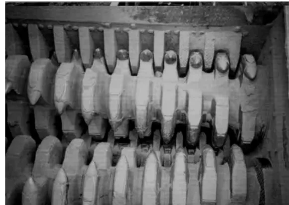
The oil sands industry in Northern Alberta is a relatively new but rapidly growing mining and mineral processing sector with enormous strategic and commercial value to Canada. Latterly the traditional dry mining schemes used in the first decades of commercial operation, have been replaced by hydraulic ore transportation. This has brought about an increased need for effective and reliable crusher, breaker, sizer (Figure 1) and classifying systems to comminute, screen and handle large rocks and oil sands lumps prior to slurrying and pipelining the ore to bitumen extraction and separation processes. This is particularly demanding when the oil sand is in a frozen state during winter mining when temperatures can fall to below -40°C.
Figure 1. Sizer for crushing rock and frozen oil sands lumps
This situation has presented another wear materials challenge to an industry that has perpetually faced very severe abrasion and erosion problems caused mainly by fine quartz grains that constitute the bulk of oil sands deposits. Gouging abrasion involving larger solids and high indentation and impact forces, has made a much lower contribution to overall wear in previous dry mining schemes than low and high stress abrasion and rolling contact abrasion modes (Llewellyn, 1997). Unlike these mechanisms, laboratory testing under gouging abrasion conditions has not been carried out previously to evaluate and compare material options specifically for oil sands service.
A procedure based on the ASTM G81 specification
has been claimed that it closely models field
range of materials has been evaluated in the past.
he materials selected for this program covered a
Table 1. Steels and white irons
Type Ident. Ha Description
has been used in the present work. It is a method for determining gouging abrasion resistance using a jaw crusher. It and variants have been employed mainly to assess materials for crushing and grinding service (Tylczak et al., 1999; Hawk et al., 1999; Marks et al., 1976, and Borik, 1972).
It
abrasion conditions on crushers, shovel and excavator teeth and scoop lips thus it has direct relevance to the oil sands industry which employs double roll crushers and sizers with arrays of breaker tips (Figure 1). However, the evaluation also has relevance to materials for rotary breakers, tractor undercarriage parts, shovel bucket lips, truck boxes, open gears and chains.
A
These have included structural steels, white irons, manganese steels and chrome carbide (CrC) overlay materials (Tabrett et al., 1996; Bednarz, 1999; Hawk et al., 1999; Tylczak et al., 1999). T
range of well-established and more recently developed products. This included abrasion resistant, quenched and tempered rolled steel plates to nominally 600 HB hardness, austenitic manganese steel and hypereutectic and CrMo white iron castings and laminates, CrC overlays and plasma transferred arc welded (PTAW) tungsten carbide (WC)-based hardfacing deposits. With the exception of Mn steel, which is a traditional choice for some crusher components in hard rock mining, all material types are being used in various gouging abrasion and other high wear situations in oil sand operations. The successful
use of WC hardfacing particularly as PTAW deposits, on a variety of oil sands wear components has grown very significantly over the last ten years but there have been no comparative properties data available for this specific wear condition.
2. MATERIALS
The test and reference plates used for this work were nominally 19 mm or 25.4 mm in thickness. Details of the materials tested are given in Tables 1 & 2.
The plates were cut to provide 76.2 mm wide, 229 mm long sections with ends tapered to fit into specially designed holders. In addition, test surfaces were ground to a flat, consistent finish to remove any decarburized layers in steels and any surface zones in tungsten carbide overlays that could have suffered sinking of dense carbide particles in the weld pool during deposition. Hardness tests were carried out on all ground test surfaces and are also reported in Tables 1 & 2.
3. GOUGING ABRASION TESTING
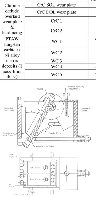
3.1 Equipment
The crusher system and plate assembly are shown schematically in Figure 2. As stipulated, plates were arranged such that a test material was facing a reference steel. The minimum jaw opening was set as specified at 3.2 mm. The test was stopped regularly to confirm the gap and reset if necessary.
rdness - HB
Q & T 100 232 -240 Reference ASTM A 514 Grade B rolled structural steel
AR 400 384
AR 450 390
AR 500 462
AR 600 552
Rolled CMnB abrasion resistant (AR) steels. Quenched and tempered to various nominal hardness
levels.
AR 450 (TRIP) 435 TRIP (Transformation induced by plasticity) AR steel Steels
AustMnSt 205 Solution treated ASTM A 128 Grade A austenitic
manganese steel casting
CrMo WI 730 ASTM A532 11B (3%C 15%Cr 3%Mo) alloy
White Iron H
Castings yperCrWI 710 Proprietary hypereutectic Cr white iron
Lam. CrMo WI 755 ASTM A532 11B alloy casting brazed to a steel backing plate
L
Plates Lam. HyperCrWI 640
Proprietary hypere asting brazed to a steel backing plate
aminated White Iron
Wear utectic Cr WI c
Table 2. O Hardnes HB(*HRC) verlays s – Description Type Ident.
CrC SOL wear plate 564 6.4 mm one pass ~ 4%C 30%Cr bal. Fe deposit CrC DOL wear plate 595 9.6 mm two pass ~ 4%C 30%Cr bal. Fe deposit
CrC 1 585 9 mm two pass 7%C 28%Cr bal. Fe deposit
Chrome carbide overlaid wear plate hardfacing Fe deposit &
CrC 2 621 9 mm two pass 5%C 25%Cr 1%Mo 0.5%B bal.
WC1 46-49* 60Wt.% cast and crushed WC.W2C eutectic
carbide in a 50HRC matrix
WC 2 40.6* 60Wt.% macrocrystalline (monolithic) WC in a 30HRC matrix WC 3 48.5* 60Wt.% macro. WC in a 50HRC matrix WC 4 42-55* 65Wt.% macro. WC in a 30-35HRC matrix PTAW carbide / tungsten deposits (1 p Ni alloy matrix ass 4mm
thick) WC 5 52-55* 65Wt.% macro. WC in a 50HRC matrix
Figure 2. Schematics (top) of jaw crusher and (lower) of test/reference plate arrangement.
Figure 3. Pre-crushed rock feed (left) and crushed product (right).
weight ng
fraction ic,
18.8% granitic and 16.3% of other rock types. A omparison of the rock before and after crushing is
ughput. It was determined at there was a linear relationship between the
and the amount of material rushed. These results correlated with information
r WC verlay materials and no quantified data for CrC
luated using ported density values. A final test wear ratio WF Pre-crushed morainal rock with a size range of 25
to 50 mm was used as the jaw crusher feed. The
% composition consisted of the followi s: 44.2% volcanic, 20.7% metamorph c
illustrated in Figure 3.
3.2 Procedure
In an initial test, plates were weighed at four ~ 227 kg intervals up to the ASTM G81 recommendation of 909 kg of rock thro
th
plate weight loss c
published previously (Marks et al., 1976).
It was decided that reliable results could be obtained for steels and white iron castings after crushing only 455 kg of rock. This significantly reduced testing time and labour. However, since there was no gouging abrasion test results fo o
overlays, and as it was anticipated that they would both display very low losses, they were tested using 909 kg of rock to obtain more easily measured values. This difference does not invalidate data as every assessment also involved a comparison against reference plates.
Moveable and stationary test and reference plates were cleaned and weighed before and after crushing and the mass loss recorded. From this result a volume loss could be easily obtained for all the ferrous-based materials eva
re
could then be calculated using the following formula.
4
reference plates. In all instances except
for WC erials
ere very similar and the mass losses could be
re based on reported ensities of 15.6 g/cc and 16.55 g/cc for monolithic
lometry. HS abrasion wear ars were relatively small and very suitable for
. GOUGING ABRASION TEST DATA
CrMo white iron laminated wear late which was the superior performer in the first sting campaign, has also been included in Figure
Figure 4. ASTM G81 WF values for steels and white iron castings and laminated wear plates.
. WEAR SURFACES AND STRUCTURES
tron icroscopy and metallography from the regions of ighest gouging abrasion attack
.
These were dge of stationary plates.reagent used for white ons castings and CrC overlays was Glyceregia.
re 6) compared to scoring ttack of AR steels which decreased as their
ere was much lower amage to CrMo castings and laminates (Figure 7).
f a Q&T 1
WF = 0.5 (XS/RS + XM/RM) (1)
Where Xs and Xm are the volume losses for the
stationary and movable test plate and RS and RM
are the volume losses for the stationary and moveable
overlays, the densities of the test mat w
used to calculate WF values.
In the case of composite WC materials, theoretical density values of 11.73 g/cc for WC overlays and 12.17 g/cc for the eutectic WC.W2C form were
used for 60% carbide deposits and 13.08 g/cc for 65% WC overlays. These we
d
and eutectic carbides respectively and 8.4 g/cc for nickel matrix alloys.
The validity of this approach has been supported using high stress (HS) steel wheel abrasion tests on identical materials. Calculated volume losses compared fairly closely with values measured directly by laser profi
sc
laser profilometry compared to the areas involved in gouging abrasion test plates which were too large to be scanned reliably.
One very noticeable characteristic was that stationary plates suffered much greater attack than moveable parts.
4
Wear Factor values are presented in Figures 4 and 5. The value for
p te
5 for comparison purposes.
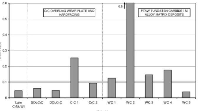
Figure 5. ASTM G81 WF values for CrC wear plates and hardfacing and PTAW WC overlays.
Multiple tests were carried out on several of the materials and good consistency was obtained.
5
Sections were cut for scanning elec m
h
located approximately 25 mm from the bottom e
Steels were examined metallographically, after etching with 4% nital except for AustMnSt which was etched in 4% nital, rinsed in methanol and re-etched in 15% HCl. The
ir
The PTAW WC based deposits were examined in the unetched condition.
5.1 Surface Damage
Significant micro-scratching had occurred to the soft reference steel (Figu
a
hardness increased. Th d
Figure 6. Scoring damage to the surface o 00 steel reference plate.
0 0.1 0.2
AR 400 AR 450 AR 500 AR 600 AR 450
(TRIP)
AustMn CrMoWI HyperCrWI Lam
CrMoWI Lam HyperCrWI Material W ear Factor 0.3 0.4 0.5 0.6
STEELS WHITE IRON CASTINGS
LAMINATED WHITE IRON WEAR PLATES
0 0.1 0.2 Lam CrMoWI SOLCrC DOLCrC CrC 1 CrC 2 WC 1 WC 2 WC 3 WC 4 WC 5 Material W ear F acto r 0.3 0.4 0.5 0.6 0.8
CrC OVERLAID WEAR PLATE AND PTAW TUNGSTEN CARBIDE / Ni
HARDFACING ALLOY MATRIX DEPOSITS
d p te.
urfaces of many of the overlay materials
frac e high C
the
nce steel plates had suffered n distortion unced in AR rock 100 refer ct zone. Aust
echanical twinning (Figure 12) and significant work hardening in
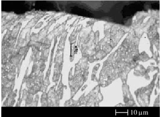
Figure 7. Limited depth micro-scoring an indentation in the surface of LamCrMoWI la
S
particularly those with structures with higher volume fractions (CVF) of hard carbides, exhibited a combination of micro-fracturing of M7C3
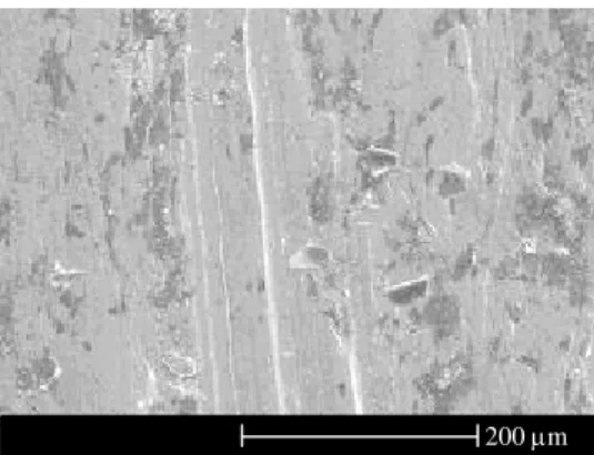
carbides in CrC materials (Figure 8) and of WC and eutectic carbides in PTAW tungsten carbide-based overlays (Figure 9). Micro-scoring was also pronounced in the softer Ni alloy matrices of the latter deposits.
Figure 8. Scoring and widespread micro-turing of M7C3 carbides in th
content CrC1 hardfacing.
Figure 9. Micro-cracking of WC carbides and micro-scratching of the Ni-based matrix in WC5 PTAW overlay.
5.2 Microstructural Features
Surface zones of refere
significant deformation and grai (Figure 10). This became less prono
steel test plates with increasing hardness, as illustrated for the AR 450 (TRIP) steel in which adiabatic shear bands had developed in the worked surface zone (Figure 11).
Figure 10. Pronounced grain distortion in the crushing contact zone of Q&T ence steel.
Figure 11. Less grain distortion and adiabatic shear bands in the AR 450(TRIP) steel conta
Figure 12. Work hardened surface of the MnSt casting. 200 µm 100 µm 100 µm 50 µm 50 µm 100 µm M
microhardness values in excess of 450 HV provided evidence of
the contact zone of the austenitic manganese steel
when their carbide structures were omparable. Hypoeutectic or eutectic forms
e
eute e of
CVF and at larger primary carbide zes (Figure 14).
Figure carbide
% C,
ion and its nominal
m trix. It
dam
n e
igure 16. Uneven distribution of micro-actured WC grains at the contact surface of
white iron
7 3
plate.
Cr and CrMo white iron materials as castings and weld deposits, exhibited similarities in surface damage
c
displayed some ability to be indented and to deform without resulting in micro-fracture of eutectic M7C3 carbides (Figure 13).
Figure 13. Indentation and deformation of th ctic structure in the surfac LamCrMoWI.
An increased propensity to cracking and spalling of primary carbides was prevalent in hypereutectic forms at higher
si
14. Significant primary M7C3
cracking at the contact surface of the 7 high CVF CrC1 hardfacing.
Damage to tungsten carbide PTAW deposits was influenced by the uniformity of carbide distribution; its volume fract
matrix hardness. Of the two 65Wt.% carbide bearing overlays, WC5 was the most resistant
a soft matrix product with an uneven carbide structure (Figure 16).
Figure 15. Limited carbide cracking in a uniformly distributed carbide structure of th hard matrix WC5 PTAW deposit.
F fr
the soft matrix WC4
product evaluated. It consisted of a dense onolithic carbide dispersion in a hard ma exhibited much less carbide cracking and spalling
age (Figure 15) compared to WC4 which was
PTAW overlay.
6. DISCUSSION
Very pronounced differences in gouging abrasion erformance were observed between the different p
classes of materials and also between products from the same class.
The most resistant materials displaying the lowest WF values were: a 65% WC-bearing PTAW
verlay; ASTM A532 IIB CrMo 10 µm
50 µm
50 µm
o
(casting and laminate) and a double pass CrC weld overlay plate material.
The heat - treated, eutectic structure of CrMo WI plates containing a significant distribution of fine utectic and secondary M C carbides in a hard e
martensitic matrix, appeared to be particularly well suited for resisting gouging abrasion attack.
These products also have a capability to be produced in relatively thick sections.
50 µm
The likely service performance benefits suggested by the slightly superior WF value for the PTAW deposit, would arguably be overshadowed by the ct that the thickness of its protective surface layer
d likely ase metal dilution. Thus it would not compare
came higher as the increasing fraction nd size of hard and brittle primary M7C3 carbides
the resence of a consistent dense carbide structure in
e cheaper, ightly harder, cast and crushed eutectic form,
the ommercial PTAW WC and hypereutectic CrC
steel was more resistant than a andard Q&T AR 450 steel plate but it did not
ic manganese steel had ork hardened to 450 HB and in this condition it ad displayed a WF value that was similar to that
l.
nsidered to be the superior option of e products assessed when the thickness of
r white iron castings and CrC ardfacing alloys were prone to micro-cracking
relatively thin PTAW 65% WC/50HRC nickel
W deposits combined ith hard Ni alloy matrices displayed superior
oft Ni–based matrices were not conducive to
acrocrystalline and eutectic tungsten carbides re comparable.
late exhibited superior WF values to ore expensive and thinner claddings of some ypereutectic CrC overlays and soft matrix PTAW fa
would be much less than that available for CrMo WI, in either straight casting or laminate forms. The behaviour of the DOL CrC wear plate was considered to be non-representative as it was not in its nominal hypereutectic condition. Ironically its high hardness hypoeutectic structure involving relatively fine eutectic carbides, provided a much tougher condition than its intended form. As in the case of all weld-deposited hardfacing layers, it would suffer from thickness limitations an
b
favourably with CrMo white iron castings and laminates, in overall protection capability.
The presence of high M7C3 carbide volume
fractions and particularly those containing coarse primary carbides, affected deleteriously the gouging abrasion performance of hypereutectic Cr white iron castings and more obviously CrC weld overlays and hardfacing. The WF values for these alloys be
a
enhanced their propensity to cracking and spalling damage.
Raising the nominal carbide content in PTAW deposits from 60 to 65% resulted in superior performance but more important influences appeared to be the matrix hardness and to a lesser extent the uniformity of carbide distribution. It is considered that the wear resistance and support provided by a high matrix hardness and p
the contact surface, are critical requirements to minimize micro-cracking and spalling damage. There was no clear distinction between monolithic / macrocrystalline WC and th
sl
when present in similar nominal contents in PTAW deposits with the same matrix hardness.
The performance of AR steels was influenced by their hardness with the AR 600 grade exhibiting GA resistance that was superior to some of c
hardfacing products. Steel plate properties would also be maintained throughout their thickness The TRIP AR 450
st
satisfy a claim that it could match the performance of AR 500 steel.
The surface of the austenit w
h
of 450 HB Q&T AR stee
7. CONCLUSIONS
ASTM A532 11B CrMo white iron castings exhibited very high resistance to gouging abrasion. They were co
th
available wear protection layer was included in the comparison.
High C - bearing C h
and micro-spalling of primary M7C3 carbides and
were less resistant A
alloy matrix deposit, provided the lowest WF value or highest GA resistance.
Higher WC-bearing PTA w
GA resistance compared to lower carbide content /softer binder composites.
S
achieving low GA wear factors in PTAW WC deposits.
M
behaved similarly in PTAW deposits when other factors we
The WF of AR steels was inversely proportional to hardness. AR 600 steel p m h WC deposits. 8. REFERENCES
Bednarz, B. (1999), Abrasive Wear of Hardfacing
Materials, Australasian Welding Journal, 44, (2), 40-43.
Borik, F. (1972), Using Tests to Define the
Influence of Metallurgical Variables on Abrasion,
999). Laboratory Wear Test Investigations
0 (1012),
ysical Metallurgy
ips in
Abrasion and Field ear Results. Wear, (225-229) 1059-1069.
ood F.W., Sare, I.R and Constantine, A.G.,
is of Jaw Crusher ouging Abrasion Tests. Journal of Testing and
ppreciated. Contributions by Lynsey Driver, onald Tolfree, Perry Liang, Dhade Setiaputra, evin Hergott and Persio Rosario, to testing and xamination of materials and to compilation of the ata and this paper are acknowledged gratefully. Metals Engineering Quarterly, (2), 33-39.
Hawk, J.A, Wilson. R, Tylczak, J.H. and Dogan, O.N., (1
of Test Methods and Alloy Correlation. Wear, (225-229), 1031-1042.
Llewellyn, R. (1997), Resisting Wear in Oil Sands
Mining and Processing, CIM Bulletin 9 75-82.
Marks, G.L., Mutton, P.J., and Watson, J.D. (1976), Gouging Abrasion Tests on Several Irons
and Steels. Broken Hill Proprietary Melbourne Research Lab. Report MRL/113/76/002.
Sare, I.R. and Arnold, B.K., (1995). The Effect of
Heat Treatment on the Gouging Abrasion Resistance of Alloy White Cast Irons. Metallurgical and Materials Transactions A. Ph
and Materials Science. 26A (2), 357-370.
Tabrett, C.P., Sare, I.R. and Ghomashci, M.R, (1996), Microstructure-property relationsh
high chromium white iron alloys. International Material Reviews, (41) 2, 59-83.
Tylczak, J.H, Hawk, J.A and Wilson. R. (1999), A
Comparison of Laboratory W
W
(1991), Design and Analys
G
Evaluation. (19) 5, 408-412.
ACKNOWLEDGEMENTS
The authors would like to thank sponsoring members of the Collaborative NRC/Industry Mining Wear Materials Program for their support of this work. The generosity of the manufacturers who supplied the test plates is also very much a D K e d