Development of a Museum-Quality Display of Mechanisms
by
Trevor Shannon
Submitted to the Department of Mechanical Engineering in Partial Fulfillment of the Requirements for the degree of
Bachelor of Science in Mechanical Engineering at the
Massachusetts Institute of Technology
June 2011
02011 Trevor Shannon
All rights reserved
MASSACHUSETTS INSTITUTE
OF TECHNOLOGY
OCT
2 0
2011
LIBRARIES
ARCHIVES
The author hereby grants to MIT permission to reproduce and to distribute publicly paper and electronic copies of this thesis document in whole or in part in any medium now known or
hereafter created.
Signature of Author:
Department of Mechanical Engineering May 6, 2011 .1 1 Certified by:
J
Barbara Hughey, PhD Instructor [hesis Supervis Accepted by: Professor J. Lienhard V Collins Professor of Mechanical EngineeringChairman, Undergraduate Thesis Committee
Acknowledgements
Dr. Barbara Hughey, for providing inspiration, knowledge, and support Bill Cormier, for providing sound design advice
Development of a Museum-Quality Display of Mechanisms
byTrevor Shannon
Submitted to the Department of Mechanical Engineering on May 12, 2011 in Partial Fulfillment of the Requirements for the Degree
of Bachelor of Science in Mechanical Engineering
ABSTRACT
Three interactive models were developed as part of a museum-quality exhibit of interesting mechanisms. Models of Peaucellier's linkage, Klann's linkage, and a Geneva drive were designed, analyzed, and fabricated. Peaucellier's linkage is a simple mechanism that contains seven links and is able to generate a mathematically exact straight line from only the rotation of cleverly-arranged rigid members. Klann's linkage is able to simulate the walking motion of an animal and is often compared to a crab or spider gait. A Geneva drive is a device that converts continuous into intermittent rotary motion. The models were made from brass and aluminum for both the aesthetically-pleasing quality and relative durability of the materials. All three models were created successfully and work quite well. However, as with any project, there are a few aspects of the mechanisms that could be improved, namely excessive deflections in the Klann linkage and interference issues in the Peaucellier linkage model. The ultimate goal for these exhibit pieces is to display them in the Pappalardo Laboratory for educational purposes.
Thesis Supervisor: Dr. Barbara Hughey Title: Instructor
CONTENTS
D evelopm ent of a M useum -Quality Display of M echanism s ... 1
A b stra c t ... 3
C o n te n ts ... 4
1. Introduction ... 5
2. Candidate M echanism s for Study... 5
2.1 W ankel Engine ... 6
2.2 D ifferential Gears ... 7
2.3 U nconventional G ears ... 8
2.4 H art's Linkage... 9
3. Developm ent of a Peaucellier's Linkage M odel ... 10
3.1 G enerating Straight Lines... 10
3.2 D esigning a Peaucellier's Linkage M odel ... 11
3.3 Fabricating a Peaucellier's Linkage M odel... 15
3.4 A nalysis of Peaucellier's Linkage M otion... 18
4. Developm ent of a Klann Linkage M odel ... 21
4.1 O f Spiders and Linkages ... 21
4.2 D esigning a Klann Linkage M odel ... 22
4.3 Fabricating a Klann Linkage M odel... 27
4.4 A nalysis of the W alking M otion... 30
5. Developm ent of a G eneva Drive M odel... 32
5.1 Clockwork and Film Projectors ... 32
5.2 D esigning a G eneva Drive M odel... 33
5.3 Fabricating a G eneva Drive M odel ... 39
5.4 A nalysis of the Geneva M ovem ent... 42
6. Conclusion... 44
7. Appendices ... 44
Appendix 1: Peaucellier Linkage Proof and Inverse Geometry... 44
Appendix 2: Derivation of Geneva Drive Geometric Conditions... 46
Appendix 3: Additional Peaucellier Linkage Im ages... 47
Appendix 4: Additional Klann Linkage Im ages ... 49
Appendix 5: Additional Geneva Drive Im ages ... 50
Appendix 6: Geneva Drive M ATLA B Script ... 51
References ... 54
Figure Sources ... 54
1.
INTRODUCTION
In the course of a mechanical engineering education, a student grows to appreciate the satisfying motions of a purely mechanical system. Through exceedingly clever arrangements of very simple gears, cams, levers, pivots, and springs, mechanisms can be assembled that exhibit a vast range of behaviors. These machines can be complex and obfuscated, a style made famous
by Rube Goldberg, or pleasingly simple and elegant. Mechanisms can be made to amuse, as
with Arthur Ganson's kinetic sculptures, or be made to do work, as with an internal combustion engine. To the mechanical engineer, nothing is more satisfying than watching a well-made machine run.
Mechanisms and mechanical systems result from the application of theory from many areas of mechanical engineering. While these fundamental theories are studied rigorously in the education of a mechanical engineer, the fascinating area of mechanisms, drives, and linkages is too often ignored. The only way to fully understand the motion of a mechanism is to physically interact with such a mechanism. This can be in the form of an actual machine partially disassembled for study, or in the form of a simple model meant to isolate one particular mechanism for observation. The work of this thesis focuses on the development of a set of relatively simple, high-quality, interactive mechanical models built for education. Hopefully, after playing with one of these model mechanisms, the viewer will leave with both a higher understanding of the physics behind the mechanism and an appreciation of its beauty.
The full designs for three models are presented as part of this thesis: Peaucellier's linkage, Klann's linkage, and a Geneva drive. Each mechanism was fabricated by the author and is presented alongside a discussion of the geometry required for that mechanism to function. Additionally, an analysis of the motion of each mechanism is presented, to supplement the models and the viewer's knowledge.
2.
CANDIDATE MECHANISMS FOR STUDY
In designing a display of mechanisms for a general audience, there are a number of considerations that must be taken into account. The display must be interesting if people are to play with it, robust if it is to endure many years at the hands of overzealous visitors, and educational so that the visitors, while playing, may just find themselves learning something. These considerations shorten the list of candidate mechanisms somewhat. A full six-speed automotive gearbox may provide insights to someone well-educated in mechanical systems, but the enormous complexity of this type of integrated system can limit the educational value of such a display. Through its simplicity, a display of a single lever can provide a very clear understanding of how such a device pivots and moves, but this would be a very boring display
indeed. Key candidate mechanisms are those that viewers may have never seen before, yet are simple enough to be explained and understood in a relatively short amount of time. What follows is a list of all the mechanisms considered for display with a short description of each. Note that this list omits the four mechanisms actually selected, as these are dealt with in detail in the following sections. The mechanisms that were selected were chosen because they are both interesting and relatively easy to build. However, this does not mean that the following mechanisms are not interesting or easy to build! Time and cost constraints simply limited the number of mechanisms that could be pursued further. Note also that the following list is not exhaustive, as any reasonable mechanism or movement can be made into an educational model.
2.1
Wankel Engine
The Wankel engine is a type of rotary internal combustion engine that uses a single rotor to convert the expansion of combustion gases into mechanical energy. The rotor of a Wankel engine has a very specific shape, similar-but not identical-to a Reuleaux triangle, that rotates inside an epitrochoid chamber (St George's Academy Maths Forum, 2010). A Reauleaux triangle is a curve of constant width, i.e. if placed between parallel planes, the planes will always be the same distance apart, regardless of the orientation of the shape in the plane (Bryant & Sangwin, 2008, p. 190). The simplest shape of constant width is a circle. The movement of the inner rotor around the complex chamber is extremely interesting to watch, as the three vertices of the inner rotor never stray from the chamber surface despite the strange geometry of both parts. Figure 2-1 shows a view of the inside of a commercial Wankel engine used to power a Mazda RX-8.
Figure 2-1. Rotor of a Wankel engine found in a Mazda RX-8 automobile. The reference for this figure (and all other figures not generated by the author) in the list of Figure Sources at the end of this thesis.
2.2
Differential Gears
A differential is a mechanism that is essential to a number of machines, most notably the
automobile. A differential drive usually consists of 3-4 bevel gears, as well as a larger drive gear, and it enables the driven wheels of a car to rotate at different speeds while still supplying torque to both wheels. When a car rounds a bend, the outer wheels need to rotate faster than the inner wheels. This is easy to achieve when the wheels can independently rotate, but this is not possible for the drive wheels of a conventional car with a single engine. Therefore a differential must be employed to ensures that neither of the drive wheels slip as the car turns. As the differential is such an important mechanism, viewers would benefit from playing with and learning about this device. Figure 2-2 below shows a drawing of the differential from a Hummer
H3.
Figure 2-2. Cutaway of a rear differential assembly from a Hummer H3 automobile.
There are other types of differential than the example shown above in Figure 2-2, though this is the most common variety of differential found in machinery, especially automobiles.
2.3
Unconventional Gears
Gears are essential to a countless number of machines and come in a number of varieties: spur, worm, bevel, etc. However, there are other types of less conventional gears that serve little or no purpose in the realm of conventional machines, but are more of a curiosity. This subset includes elliptical, angled, variable-speed, and even square gears, as shown below in Figure 2-3 below. These unconventional gears can only be really appreciated after seeing them in motion.
Figure 2-3. Square and elliptical gears part of the Clark Collection at the Museum of Science, Boston MA. Despite appearances, these gears actually mesh and transmit torque.
2.4
Hart's Linkage
Hart's linkage belongs to a family of linkages that can produce exact straight lines (Peaucellier's linkage, section 3, is another). Hart's linkage is special due to the fact that it uses only five links with pivots to produce a straight line (Bryant & Sangwin, 2008, p. 38). The motion of Hart's linkage is satisfying in that the complex motion of individual links results in an absolutely perfect straight line at the endpoint of the linkage. An example model of Hart's linkage is shown below in Figure 2-4.
3.
DEVELOPMENT OF A PEAUCELLIER'S LINKAGE MODEL
3.1
Generating Straight Lines
The Peaucellier linkage, also sometimes called the Peaucellier cell, is a simple linkage that has the unique property that its endpoint traces out an exact straight line. Peaucellier's linkage was invented by Charles Nicolas Peaucellier in 1864, and it was the first planar linkage that could produce a straight line (Bryant & Sangwin, 2008, p. 34). There are other, earlier linkages that could approximate a straight line quite well, such as Chebyshev's and Roberts's linkages, but it can be shown mathematically that Peaucellier's cell will produce (given ideal pivots and rigid links) a perfect straight line (Bryant & Sangwin, 2008, pp. 34-36).
The need for a straight line generator came in the form of James Watt's steam engine, which required a linkage to move a piston rod vertically along a line. James Watt himself is credited with the first approximate-straight line linkage, most likely a child of the above steam engine problem (Bryant & Sangwin, 2008, p. 22). When asked to make a straight line, many people will seek to use a ruler or other straightedge. However, there are two problems with this approach. First, is the so-called "straightedge" really straight? Second, given that the ruler is indeed straight, how was it itself created? Is it rulers all the way down? The first problem is an interesting one, though out of the scope of this thesis. Addressing the second problem, it is true that the simplest way to make a straight line is to somehow copy an existing straight line. However, Peaucellier's linkage is able to generate a straight line from pure rotational motion of seven links, which gives it the ability to produce the "first" straight line.
The basic Peaucellier linkage consists of seven links and six pivots. The links are of three different sizes, often with ratios similar to those shown below in Figure 3-1. The following relationships must hold for a valid Peaucellier's linkage, where the segment names match those that appear in Figure 3-1.
OA = OB = 11
AP = PB = BC = CA= 12
OQ = OC = 13
Under these conditions, the point P will be exactly constrained to a straight line that is orthogonal to line segment OQ. Peaucellier's linkage works because the inverse of a circle through the center of inversion is a straight line. In this case, 0 is the center of inversion, and the circle defined by QC is the circle that is being inverted. Bryant and Sangwin provide an excellent proof for Peaucellier's linkage, as well as a discussion of inverse geometry. See Appendix 1 for more information.
P
,- 3 B
0.h
Q
N:
Figure 3-1. Schematic of Peaucellier's linkage. The linkage consists of seven links of three lengths. Note that points 0 and Q are fixed in space. Point P is constrained such that it moves on a straight line perpendicular to OQ.
There are a number of modifications that can be made to Peaucellier's linkage while still maintaining its fundamental geometry and therefore functionality. Among these is Hart's linkage, as shown in Section 2.4, which is really just a modified and generalized version of a Peaucellier cell and sometimes called an inversor cell for its ability to invert a circle (Bryant & Sangwin, 2008, p. 37). The original form of the Peaucellier cell was chosen for this model, as it most clearly shows the geometric relationships critical to the function of the straight line generator. Additionally, other forms such as Hart's linkage require that three pivot points be placed on a single link. These pivots should themselves lie on a straight line--generating somewhat of a recursive problem! The linkage shown in Figure 3-1 avoids this problem, since there are never more than two pivots on any one link, and these two points lie by definition on a
straight line.
3.2
Designing a Peaucellier's Linkage Model
There were a number of important design considerations in the development of this linkage. The most obvious and important of these constraints was that of link length, which is simple to calculate given the relationships above. It is the precise configuration of correctly-sized links that give Peaucellier's linkage the unique ability to generate an exact straight line. For the model linkage, the lengths were chosen to be 11 = 5.80 inches, 12 = 2.00 inches, and 13 =
2.50 inches so that the model can fit easily on a table. However, given that this is a physical
model of a linkage, rather than an idealized one, the detailed structure of the pivot points must also be brought into consideration. The joints must be relatively easy to move so that the linkage can be actuated by the hand of a visitor, but they also must be tight enough to take up any
parasitic play in the linkage end point. Also, the pivot joints must stay assembled even after thousands of actuations. This requires both careful joint design as well as precision fabrication.
A number of different designs were considered for the linkage pivot joints. Among these
designs were three viable options: standard shoulder bolts, custom press-fit pins, and custom threaded pins. The three designs for a simple pin joint connecting two links are diagrammed below in Figure 3-2. Should the colors be visible, the two links being connected are shown in yellow, and the pins are shown in blue and red.
Figure 3-2. Three methods of creating a pin joint connecting two links: (a) shoulder bolt, (b) press-fit pin, and (c) threaded pin. The links being connected are shown in yellow and the pin assemblies are shown in red and blue.
All three designs have respective benefits and detriments. A shoulder bolt-based pivot as
in Figure 3-2(a) would be easy to disassemble, as the shoulder bolt has a slot for a flathead screwdriver. However, off-the-shelf shoulder bolts are difficult to manufacture and therefore relatively expensive. Even a simple linkage such as the Peaucellier cell contains six pin joints, and so the price to produce the linkage would be quite high, especially so for more complex linkages. A press-fit pin design-Figure 3-2(b)-avoids the cost problem, as both the male and female pins would be hand-fabricated by the author-taking advantage of student labor. However, this design would be quite difficult to disassemble once the male and female pins are press-fit together. The pins could be fabricated to have a friction fit with the ideal holding friction, but this would require extremely high-precision machining on the female pin bore and male pin outer diameter to within approximately 0.0002 inches. Finally, the threaded pin design shown in Figure 3-2(c) eliminates the extremely tight tolerances associated with a press-fit design. The joint is relatively easy to disassemble, especially if there are slots for screwdrivers in both the male and female pins. Additionally, the tightness of the joint can be adjusted by turning the threaded fastener, increasing or decreasing the preload in the joint. This custom threaded pin design was selected for Peaucellier's linkage based on the above benefits.
However, a problem with a pivot joint using a threaded fastener is that the rotary motion of one link relative to the other will tend to unscrew the fastener until the joint has significant axial play or worse-the joint self-disassembles. Any external spring washers or lock washers will affect the rotation of the joint by increasing friction on the face of one link, so these types of locking mechanisms will not work in this application. A potential solution is to use a compliant material or spring inside the bore of the female pin. The threaded male pin would come down and compress the spring, thus preloading the threads and reducing the tendency for the pivot to
unscrew. For a reasonably-sized desktop model, the springs required would have to be both extremely small and have a fairly high stiffness-a combination often difficult to find. Loctite is a commercially available threadlocking polymer that polymerizes in anaerobic conditions, i.e. when a nut is placed on a bolt. This acts to hold the nut in place and keep it from unscrewing due to vibration or, as is pertinent to this discussion, rotation of the clamped members. This is a simple solution that both locks the threaded fastener and preserves the ability for the joint to be disassembled-Loctite depolymerizes under the high temperatures from a lighter or heat gun.
Figure 3-3 shows a cross section of the final pin joint design. This design uses a standard 4-40 threaded machine screw as the male pin and a custom female pin. The faces of both the male and female pins lie nearly flush with the links, which is critical in linkages (such as Peaucellier's linkage) in which links pass over or under other pin joints at some point in the linkage's range of motion. Spacers are necessary to keep links from rubbing each other in any place other than the pivot-simple #8 washers were used in the design below. Note that the middle link is counterbored like the outer two, despite the fact that there is no screw or pin head in that space. Each link was designed with two counterbored holes whether or not they were going to be used so that the links themselves were standardized.
Female pvot pmn Links #8 washers 4-40 machine screw
Figure 3-3. Section view of the pin joint designed for Peaucellier's linkage. This particular joint connects three links, separated by two washers.
An additional implication of fabricating a physical (non-idealized) linkage model is that links have a finite width and thickness. Solid links cannot simply pass through one another as they can in a theoretical linkage made of lines and points. In designing a model linkage, it is beneficial to have links as slender as possible to give the largest final range of motion. The vertical arrangement of links was carefully considered to avoid link collisions while still creating a compact model. This "link stack" can be seen in the lower half of Figure 3-4.
Other design considerations included aesthetic quality, durability, and user interaction. The aesthetic of the Peaucellier's linkage model was inspired by those created by John Bryant, co-author of How Round is Your Circle?. The links themselves are made of polished brass, and the pins are polished aluminum. This combination of polished metals creates an exceedingly beautiful model that compliments the beauty of the linkage movement nicely. Durability was also of concern, as the model is to be used by many visitors over a long period of time. For this reason, only metal components were used, as many plastics wear quickly. Brass is actually quite a soft metal, but the links were designed to be thick enough to be sufficiently stiff and durable-each link is fabricated from 1/8 inch brass plate.
The final design consideration was one of human interaction. For this model to function as an educational display, viewers need to have the opportunity to interact with the linkage. For this reason, the Peaucellier's linkage model was designed without any kind of actuator. Each visitor is able to interact with the linkage endpoint, enabling him or her to gain an intuitive feel for how the linkage behaves and moves. The physical interaction is done through a modified joint pin in the linkage endpoint that serves as a small hande.
With all these design considerations in mind, the linkage model shown in Figure 3-4 was developed.
Figure 3-4. The Peaucellier's linkage model developed. The links are brass while the pins are aluminum, and the endpoint has a handle for interaction. Note that the mounting base is omitted for clarity.
3.3
Fabricating a Peaucellier's Linkage Model
Nearly all the components of the Peaucellier's linkage model were fabricated by the author. The brass links were made on a waterjet machining center with undersize holes. These holes were then drilled out and counterbored for the pivot pins on a milling machine. Figure 3-5
below shows an example of some of the finished links.
Figure 3-5. Four identical links fabricated for the Peaucellier's linkage model. The brass links were cut on a waterjet machine, and then the pivot holes were drilled and counterbored on a milling machine. Note each link is approximately 2.5 inches long.
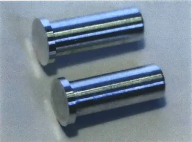
The female pivot pins themselves were fabricated out of aluminum on a lathe. This model has 3 different lengths of pivot pin, though each one uses the same length screw for assembly. Blanks were cut from aluminum round stock, and a hole was drilled and tapped in the end of each blank. These blanks were then turned down to the appropriate dimensions to finish the pins, as shown in Figure 3-6. Care was taken when finishing the face of the pin, as that surface showed in the finished linkage.
Figure 3-6. Two of the completed aluminum female pins used in the Peaucellier's linkage joints. There are tapped holes on the side not visible in this figure. Note each pin is approximately 0.5 inches long.
One of the pivot pins was specialized in that it served as the handle of the linkage. This part was also fabricated on the lathe, though the process was more complex. The finished handle pin is shown in Figure 3-7. The handle has the same dimensions as a standard pin where it interfaces with the links.
Figure 3-7. Finished handle pin for Peaucellier's linkage, turned from aluminum on a lathe. The features closest in this figure interface with the links and are therefore the same dimensions as a standard pin. The part is approximately 1.5 inches long.
To prevent the links from colliding with each other when the linkage is actuated, spacers were designed to separate the links (see Figure 3-4). These are very simple parts that were turned from aluminum on a lathe. Figure 3-8 shows the complete set of four spacers fabricated for this linkage.
Figure 3-8. Set of spacers fabricated for the Peaucellier's model linkage. inches in diameter and turned on a lathe from aluminum.
The parts are 0.375
Assembly of the linkage model was fairly straight forward. With each part fabricated as designed and within tolerances, there were no difficulties assembling each of the components into a linkage. Each joint was assembled using the appropriate links, spacers, and pin, with the holding screw tightened to prevent rotation. Then the screw from a single joint was removed,
and a drop of Loctite 243 threadlocker was put on the screw threads. The screw was then put back into the assembly such that the joint was free to rotate with minimal axial play, and the Loctite was left to dry. This was repeated for each joint to secure the assembly, which is shown below in Figure 3-9.
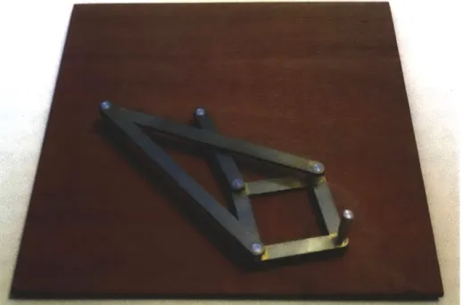
Figure 3-9. The completed Peaucellier's linkage model. The base is oil-treated plywood and is 10 x 10 inches.
Overall, the Peaucellier's linkage model worked quite well. The joints have very low friction and little play, making for a very smooth and rigid linkage. During a short stay in Dr. Hughey's lab, the linkage (and in fact all the models) proved to be both interesting and educational for students, as many came to the linkage to play with the model, then later ask questions about the motion. One problem with the model is that the lowest links scrape the wooden mounting board if the handle is pushed downward with enough force. This could be alleviated in a future revision by making the mounting base quite a bit thicker or adding a second base beneath the first to keep the two anchored pins from twisting. Additionally, if a part was added directly underneath the handle such that it contacted the wooden base before the lowest link, the downward deflection of the linkage could be controlled. This wear pin could be made of a low friction polymer or even house a pen tip for tracing the linkage's motion. It is interesting problems like these that set physical models apart from purely mathematical ones.
3.4
Analysis of Peaucellier's Linkage Motion
The entire Peaucellier's linkage model was designed using Solidworks 2010. Upon completion of the design, the motion of the model was analyzed using the Motion Analysis plug-in for Solidworks. This plug-plug-in gives the designer the ability to predict the positions, velocities,
and accelerations of parts and assemblies under certain conditions. While this type of analysis provides an idealized scenario, the actual behavior of the physical model will not vary greatly from the ideal behavior. Figure 3-10 shows a series of images representing the movement of Peaucellier's linkage. Again, the straight line produced by this linkage can be mathematically proven to be straight with inverse geometry. Essentially, under certain conditions (which the Peaucellier linkage employs), the inverse of a circle is a line. Figure 3-10 shows two motion paths: one of the straight line and one of the circle that is being inverted.
9I
Figure 3-10. Motion of Peauoellier's linkage as it traces out a straight line. Three stages in the motion are shown in red, blue, and green. The figure shows almost the full range of motion, which is physically limited by the parallelogram completely collapsing. The paths show an arc of the circle being inverted and its inverse: a line. The colored dots and angle (0) convention match the plot shown in Figure 3-11.
Given an input of constant rotational velocity on link QC (see Figure 3-1), what is the endpoint's velocity profile? This can be determined quite easily using Solidworks, and the resulting plot is shown in Figure 3-11. The orange curve shows the velocity profile of the orange point in Figure 3-10, while the purple curve shows the velocity profile of the endpoint, marked purple in Figure 3-10. When interacting with the device, it is most likely that the endpoint
(purple) will have constant velocity, as that is the point under control by the visitor. However, analyzing the reverse case-treating the endpoint as an output and giving the rotational link (orange) a constant velocity-is enlightening nonetheless. In fact, in an application where the straight line is used to move some object or otherwise do work, the point shown in purple is indeed the output, while the simpler rotational input would be provided by an oscillating motor or engine. The details of achieving this oscillatory rotational input are quite another story, likely involving a most interesting mechanism.
-C
00
-80
Endpoint Velocity vs. Relative Angle for Peaucellier's Linkage 1.5 -1.0 -0.5 -0 20 -20 -60 Angle,
e
(deg) -40Figure 3-11. Plot of the linear velocity magnitudes of two points on Peaucellier's linkage against angle 0. The points plotted are the endpoint (purple) and the end of the main rotational link (orange) as shown in Figure 3-10 above. The angle of the main rotational link is measured relative to the horizontal, also shown in Figure 3-10.
It can be seen that the linkage endpoint has the lowest velocity at the middle of its trajectory, i.e. when
E
= 0. Additionally, the acceleration of the link at this point is equal to zero,meaning that for the region around 6 = 0, a constant-velocity input will give an approximately
constant-velocity output. Also of note is the ratio between the two velocities, which is set by the relative ratios of the links.
4.
DEVELOPMENT OF A KLANN LINKAGE MODEL
4.1
Of Spiders and Linkages
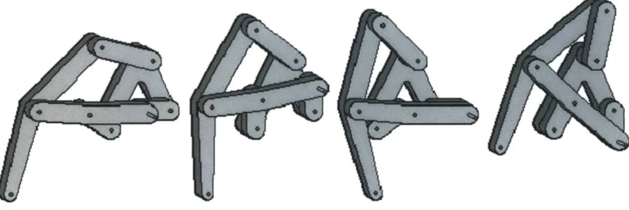
Linkages can be made to provide almost any movement required. These movements can often be quite complex, but few linkages can match the complexity of those walking linkages created by nature-legs. Joseph Klann emulated the complex movement of a natural gait with his exquisite linkage, patented in 2001 (Klann, 2001). The movement of Klann's linkage is fascinating to watch, though the series of images shown in Figure 4-1will have to suffice for this report.
Figure 4-1. Series of images showing the motion of Klann's linkage. The images show a single step, from touching the ground (left), pulling the leg so as to move along the ground (middle), to lifting the leg for another step (right).
The Klann linkage is quite similar to another walking linkage developed by Theo Jansen (Jansen), a Dutch artist who creates huge mechanical walking automata. Jansen's linkage is more complex than Klann's, though both create very organic and fluid walking motions. The Jansen linkage requires 8 links per leg, while the Klann linkage requires only 6. Additionally, three Jansen legs are required to produce smooth walking motion, while only 2 Klann legs are required to approximate walking motion.
Jansen's linkage is used nearly exclusively in his Strandbeest walking kinetic sculptures, but Klann's linkage has been used in many small robots and other personal projects. Due to its resemblance to spider or crab legs, the Klann linkage has been used in many mechanical spiders, including a huge 1,700 pound behemoth called the Mondo Spider. The Mondo Spider is a home-made, 8-legged, gasoline-powered (though recently modified to run on batteries) walking machine that is piloted by a single person sitting inside the machine (Mondo Spider, 2010). It was created by enthusiastic engineers in Vancouver, British Columbia.
4.2
Designing a Klann Linkage Model
The general design of the physical Klann linkage model is quite similar to that of the Peaucellier's linkage model, as both consist of simple rigid links connected by pin joints. Given that the pin assembly was already designed for the prior model, the most critical design decision to be made in creating the Klann linkage model was the length of each link.
In his patent, Joseph Klann provides the means for calculating a Klann linkage given six independent input parameters (Klann, 2001, pp. 20-21). Using these parameters, as well as the geometric construction given in his patent (reproduced here in Figure 4-2), an infinite number of Klann linkages can be designed. Each particular Klann linkage has slightly different properties: step path, step height, relative step phase velocities, etc.
65p
Figure 4-2. Geometric construction from Fig. 17 of Klann's patent. There are six independent parameters that can be tuned to give different gaits and linkage movements. Using this set of parameters, along with the construction, all the necessary link dimensions can be calculated.
The entire construction shown in Figure 4-2 was recreated in Solidworks as a two-dimensional drawing. Each of the six parameters could be tuned independently and the live drawing would then update to provide the new link dimensions. Using the approximate ratios of link lengths shown in Klann's diagram as a starting point, a trial-and-error process was employed for creating the final link dimensions. Potential linkages were assessed based on the aesthetic
quality of the stepping motion, as well as overall shape and aspect ratio. The final Klann linkage model was designed to have a step that adequately displayed the asymmetries and nuances of the Klann linkage motion while still retaining a fluid and bio-inspired gait. Table 4-1 gives the chosen values for each of the six input parameters of the Klann linkage design. The values shown are scaled by the stride length of the linkage, which is shown as line 50s in Mann's drawing (Figure 4-2).
Table 4-1. Input parameters selected for the Klann linkage model. The parameters are numbered, and each is matched to a feature in Klann's geometric construction in the second column. It is convenient to express parameter values normalized by stride length-line 50s in Figure 4-2.
Input Parameter Location in Figure 4-2 Selected Value (normalized
Number by stride length, 50s)
1 Distance between point 52p and line 50s 1.250
2 Radius of circle 53c 1.500
3 Angular location of point 9 on circle 53c 30.0' w.r.t horizontal
4 Angular location of point 65p on circle 53c -90.0* w.r.t. horizontal
5 Distance between points 75p and 74p 1.400
6 Distance between points 27x and 29x 0.600
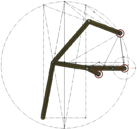
The above input parameters were used to calculate the precise geometry of each of the links. The calculated lengths were multiplied by 3.6 to give link lengths in inches, given that the model should fit easily on a table. The resulting linkage is shown superimposed on the geometric construction in Figure 4-3.
\ -I
Figure 4-3. Final Klann linkage dimensions, along with the calculated sketch showing the link lengths. Note that the circled pivots are fixed in space.
A second design consideration was the number of legs to put in the model. One leg, as
shown above, is sufficient to define the Klann linkage. However, the walking motion is best seen when two Klann linkages are vertically stacked 180 degrees out of phase. Any smoothly-walking machine would need at least these two legs to keep the center of mass a fairly uniform height off the ground. More Klann linkages could have been put into the display, though only two already gives a total of 10 links and 11 pivots, so any more would have increased fabrication time while only minimally increasing the educational benefit of the model.
The complete Klann linkage design is shown in Figure 4-4, though note that the linkage was designed to be mirrored relative to Klann's geometric construction in Figure 4-2. A pivot design identical to the one used in the Peaucellier's linkage model (Section 3.2) was employed in this model.
Lower leg
Cantilever
support Upper leg
Crank handle
Figure 4-4. Final design for a Klann linkage interactive model. There are actually two Klann linkages in parallel, oriented 180 degrees out of phase and stacked vertically. The links are brass while the pivots and spacers are aluminum. The mounting base has been omitted for clarity.
The fact that two linkages had to be held 180 degrees out of phase introduced an interesting design problem. The Klann linkage has a purely rotational input about a stationary point. The input can be seen as the two out-of-phase short links in Figure 4-4 on the left side.
These two input links create a sort of crankshaft that drives the linkage motion. If the point about which the crankshaft rotated had a pin going all the way down to the mounting plate, the lower Klann linkage would collide with this pin. Therefore, a cantilever mount was designed to hold the crankshaft in place. This cantilever is highlighted in Figure 4-5 in blue. If the main pivot pin were to extend all the way down to the base plate, the link shown in red would hit the pin, preventing the crankshaft from making a full revolution. As shown, the cantilever support gives adequate clearance for the crankshaft links while leaving all other links clear of obstacles.
Crank handle
Cantilever support
Mounting base
Figure 4-5. Detail of the cantilever support (blue) enabling a full rotation of the input crankshaft. If the pivot pin extended to the beige base, the red link would collide with it as the crankshaft rotated around. Note some links have been omitted for clarity.
A second special consideration was a means for keeping the two input crankshaft links 180
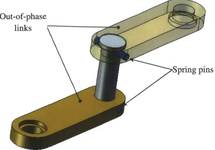
degrees out of phase, i.e. anti-parallel to each other. Three options were considered. One was to use a square hole in the crankshaft links, thus locking them rotationally to the (also square) pivot pin. A square hole (albeit with slightly rounded corners) is easy to achieve with the waterjet, but not with any great precision. The second design investigated was the use of a set screw through the sides of the two links, thus locking each link to the pivot pin. This would require the use of a very small set screw, as the links are only 0.125 inches thick. Also, set screw assemblies are known to loosen over time, which would result in a Klann walking linkage that was very much unsynchronized. The final design makes use of spring pins to hold the crankshaft links to the rotating shaft. Spring pins can be made very small and pass through clearance holes in the links and the pivot shaft, meaning they can sustain much higher torques than set screw assemblies. Figure 4-6 shows a detail of the final crankshaft locking mechanism. The shaft shown in grey has a through hole drilled near the top and a vertical slot near the bottom for the spring pins. A slot was used because two pins passing through tight-fitting holes would over constrain the assembly.
Out-of-phase links
pins
Figure 4-6. Detail view of the mechanism to lock the input crankshaft links 180 degrees out of phase. Spring pins (shown in blue) set the angular positions of both links relative to the pivot
shaft.
4.3
Fabricating a Klann Linkage Model
Being quite similar to the Peaucellier linkage model, the Klann linkage model was fabricated in much the same way. The brass links were cut with a waterjet machine and finished on a mill, while the spacers and pivot pins were turned on a lathe. Examples of the brass links made for the Klann linkage model appear in Figure 4-7. Due to the dual linkage configuration, a right and a left version of the link below had to be fabricated.
Figure 4-7. Two of the links fabricated for the Klann linkage model. For this particular link, a left and right version was required. The links were made from a brass sheet and are about 5 inches long.
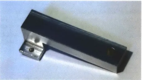
The somewhat unique cantilevered support part was also fabricated on the mill from a solid piece of aluminum. This part is shown in Figure 4-8.
Figure 4-8. The cantilevered support fabricated to hold the Klann linkage crankshaft in place. This part is approximately 3 inches long and was milled from a block of aluminum.
The pins, which are very similar to those produced for the Peaucellier linkage model, appear in Figure 4-9. There was some difficulty in producing the smallest pins, as they had to have a threaded hole deep enough for the linkage joint screws to go into. The threaded holes had to be tapped with a bottoming tap, and care was taken to not break through the face of the pin, since the pin length and bore depth were very close.
Figure 4-9. All the pivot pins made for the Klann linkage. The pins are made of aluminum, and the longes one is about 1 inch long.
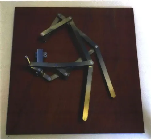
The remaining components-the handle pin and spacers-are nearly identical to those designed and made for the Peaucellier linkage, and so images of the final parts would not provide much additional information. Assembly was also very similar to that of the Peaucellier linkage model, with the additional step of pressing in the crankshaft spring pins. The final linkage is shown below in Figure 4-10.
Figure 4-10. The completed Klann's linkage model. The mounting base is oil-treated plywood and is 11 x 12 inches.
For the most part, the Klann linkage worked as expected. However, the physical model revealed something that neither the calculations nor SolidWorks made apparent. At two places around the crank's path, the linkage nearly binds. This makes the model difficult to interact with, and could eventually lead to failure of one or more parts in the linkage. The binding points occur just as the legs are passing through the point of maximum velocity. At this point, one of the links becomes nearly parallel with the force vector being applied to that link (see Figure
4-11). Since the links can only rotate, only the component of the force perpendicular to the link
causes the desired motion. Since the force and the link are nearly parallel, a very large force is required to achieve the necessary tangential force needed to continue the linkage motion. If the link did ever become exactly parallel to the applied force, a full binding point would be observed. One way to fix this problem is to use a different permutation of Mann's linkage, but that requires re-fabricating almost all the links. A simpler solution would be to better support the fixed pivot attached to the offending link so that it does not deflect as much when under the high
loads caused by the near-binding point. This could be done with a thicker mounting base or through other means. Figure 4-11 shows a detail of the Klann linkage at the troublesome point. The relative angle between the link and the applied force vector is called out in the figure.
Figure 4-11. Detail of the Klann linkage model showing the cause of a near-binding point in the linkage motion. The annotated link and the force applied to that link are nearly parallel at the sticking point, resulting in a very large required torque at the crank to produce a tangential force high enough to continue the linkage motion. The photograph was taken after the sticking point.
4.4
Analysis of the Walking Motion
The movement of Klann's linkage is wonderful to watch, primarily because of its similarity to a natural gait. The underlying reasons for this similarity can be discerned by analyzing the linkage motion in detail. The most obvious reason lies in the path of the linkage "foot" or endpoint. The profile of a single step is highly asymmetric, as shown in Figure 4-12. The motion of a single step includes a very linear region when the foot is at its lowest point followed by a quick rise and fall before beginning the next step. This rise is generally characterized by a larger vertical displacement (step height) than horizontal displacement (step stride), though this ratio can be adjusted through link geometry. The ratio between vertical and horizontal motion can significantly alter the aesthetic feel of the linkage. The motion of the linkage designed for this thesis was analyzed using Solidworks Motion Analysis, and the resulting path traces appear in Figure 4-12. Only one Klann linkage is shown for simplicity. For a series of images showing the complete motion of Klann's linkage, see Appendix 4.
Linkage endpoint
4
2
Figure 4-12. Traced paths of three different points on the Klann linkage designed for this thesis. The endpoint "foot" path is shown in the lower right while the rotary input is on the left. The numbers along the step profile match those shown on the plot of Figure 4-13. The mounting plate has been omitted for clarity.
The motion path of a single step is a very interesting shape. However, the shape provides only part of the linkage motion. The speed of the linkage "foot" at various points in a single step is also both important and intriguing. Figure 4-13 shows a plot of the endpoint velocity (magnitude) as a function of the input crank angle for a constant rotational velocity input. The input link angle is measured counter-clockwise from the horizontal. The locations along the step path called out in Figure 4-12 above also appear in the plot below. Note that the maximum velocity occurs as the foot is coming down for the next step (point 4), giving the marching effect in the linkage's gait. It is also interesting to note that the minimum velocity occurs both at the beginning of a stride and also at the end (points 1 and 2). The endpoint velocity goes through a local minimum at the peak of the step height (point 3), creating a wonderful hesitation in the linkage motion before the rapid and dramatic downward step. It is the combination of the asymmetric endpoint path and the highly variable endpoint velocity that creates the fluid stepping motion so characteristic of Klann's linkage.
Figure 4-13. Plot showing the magnitude of the Klann linkage endpoint (foot) velocity for a constant-velocity rotary input. The numbers called out on the plot match those in Figure 4-12.
5.
DEVELOPMENT OF A GENEVA DRIVE MODEL
5.1
Clockwork and Film Projectors
The Geneva drive is a very elegant mechanism for converting continuous rotary motion into intermittent rotary motion. The mechanism consists of two wheels-one driving (input) and one driven (output). The input is generally rotated at a constant speed, as this type of motion is easy to obtain through an electric motor or other engine. For each full rotation of the input wheel, the output wheel rotates through some integer fraction of a full rotation. The Geneva drive is one-way, meaning that the mechanism cannot be back-driven by rotating the output wheel. The drive wheel, however, can be rotated either clockwise or counter-clockwise during normal operation.
Intermittent motion is accomplished through the use of slots and a peg. The continuously-rotating input wheel has, near its circumference, a peg which interfaces with a number of slots in the output wheel. Each time the input wheel rotates around, the pin engages in one of the slots, incrementing the position of the output wheel. A simple Geneva drive schematic is shown in Figure 5-1, with the input wheel colored blue and the output wheel colored red. More specifically, the Geneva drive shown below is an external Geneva drive, because the slots on the
Endpoint Velocity Through a Single Step for Klann's Linkage
4.0 4 3.0 2.0 a ~1.0 0 0 45 90 135 180 225 270 315 360
driven wheel are external to the part. The drive wheel often has features that prevent the rotation of the output wheel during the dwell periods (i.e. when the pin is not in any slot). This is represented by the smaller diameter arc on the drive wheel shown below in Figure 5-1.
Pin
Drive
Driven
wheel
wheel
Figure 5-1. Illustration of a Geneva drive, which converts a continuous rotary input (blue wheel) into an intermittent rotary output (red wheel). Four stages in the motion are shown.
The Geneva drive was originally developed for use in watches and clocks. The initial Geneva drives used in clocks had one or more of the slots in the output wheel blocked. This limited the number of rotations the input wheel could go through before hitting the mechanical stop of the blocked slot. For example, if one of the slots in the Geneva drive shown in Figure 5-1 is blocked, then the drive wheel can only go through a maximum of three full rotations before the blocked slot aligns with the pin, thus preventing the drive wheel from rotating any further in that direction. This configuration is called the Geneva stop and was used to prevent the over-winding of clock springs (Taimina). Geneva drives have also been used in film projectors (Kirkpatrick &
Kurtz, 2001), dispensing machines (Skarivoda, 1998), and timers (Butterworth, Minshull, Wells,
& Young, 2008).
5.2
Designing a Geneva Drive Model
The Geneva drive consists of a fairly simple drive wheel and a fairly complex driven wheel. A Geneva drive has a number of tunable parameters, including number of slots, driven wheel diameter, drive wheel diameter, slot width, etc. However, these parameters are not all independent. The pin of any Geneva drive needs to always line up with one slot, otherwise the drive will not function. This geometric condition defines a parameter space of valid Geneva drive configurations. The most important parameters defining a Geneva drive are: the distance from the center of the drive wheel to the pin, r1, the radius of the driven wheel, r2, the separation
of the wheel centers, d, and the number of slots in the driven wheel, n. These parameters are shown in the schematic of Figure 5-2. Note that the angle 2a is equal to 27r/n where n is the number of slots, or equivalently, the number of increments in one full rotation of the output wheel. Additionally, it is important to note that the slot length must be at least r1 - (d - r2) to
Figure 5-2. Schematic showing critical Geneva drive parameters. The drive wheel is represented
by the left circle while the slotted driven wheel is represented by the right circle. The angle
through which the slotted wheel rotates is defined by the number of slots.
All four of the above parameters are dependent upon one another. However, it makes
sense for the number of slots to be tunable while the other three variables are calculated. The number of slots was chosen to be an adjustable parameter because n is limited to integers and because it affects the aesthetics of the Geneva drive. Also, for Geneva drives used in machinery, the number of increments per full rotation of the output wheel is often critical to the machinery's function and should therefore be user-defined, not a free variable. In no way does this limit the design of a Geneva drive-there are still an infinite number of possible Geneva drives for any value of n. Using the diagram in Figure 5-2, an expression for the center-to-center distance, d, can be derived in terms of the other three parameters, as in Equation 1. See Appendix 2 for the full derivation of Equation 1.
d = r12 - r22 sin2 a
+
r2 cos a ; a = - (1)Note that the expression under the radical must be positive for d to be a real number. This imposes an upper limit on the size of the output wheel.
r12 - r22 sin2
a
>
0
r2 < s
sin a (2)
Equation 1 is a function of three variables. However, as mentioned above, n is taken to be a user-defined constant, so the equation simplifies to a function of two variables-the radii of the two Geneva wheels. Functions of two variables lend themselves well to three-dimensional plots, and just such a plot is shown in Figure 5-3. The plot below was generated using a custom MATLAB script (Appendix 6) that takes as an input the number of slots in the driven wheel and outputs a plot of the permissible design space. The plot below belongs to a family of surfaces defining an n step Geneva drive. The discontinuity in the surface is due to the condition of Equation 2. Since n, and therefore a, is a constant, Equation 2 becomes linear, which is clear in Figure 5-3 by the linear form of the discontinuity in the input/output wheel radii (i.e. x-y) plane.
Admissible Dimensions for a 7 Step Geneva Drive
... ... ... ... 14--12 10 8 6 4 2 0 14
Output Wheel Radius, r2(in.)
0' 0
6 5 4
3
Input Wheel Radius, r, (in.)
Figure 5-3. Plot showing the design space for a 7 step Geneva drive. For any pair of Geneva wheel radii, the required center-to-center distance between those wheels is given by the height of the surface at that point.
The surface of Figure 5-3 can also be visualized as a two dimensional plot, such as the one shown in Figure 5-4. The output wheel radius is plotted on the horizontal axis while the center distance between Geneva wheels is plotted on the vertical axis. Curves for four different values of the input wheel radius are given. Again, note the discontinuity where the center distance becomes complex.
Center Distance Between Geneva Drive Wheels (n=7)
6 8
Output Wheel Radius, r2(in.)
Figure 5-4. Plot showing center-to-center distance between Geneva wheels radius for a number of different drive wheel radii.
against driven wheel
With a solid understanding of the geometric constraints of a Geneva drive, the design of the components comes easily. The number of slots in the output wheel was chosen to be seven for purely aesthetic reasons, given that seven is a prime number and seven-fold symmetry is not often seen. A pair of wheel radii was then chosen such that the final model could fit easily on a tabletop. This allowed the distance between wheel centers to be calculated using Equation 1. Using a trial-and-error approach, the three free parameters were tweaked until a visually-pleasing and reasonably-sized mechanism was achieved. The final parameters chosen for the model Geneva drive were r, = 1.625 inches, r2 = 3.25 inches, d = 3.736 inches, and n = 7, as shown in
Output wheel
Input wheel
Slots
Locking features
Figure 5-5. The Geneva drive developed using the geometric conditions derived above. The input wheel is brass and the output wheel is aluminum.
The output wheel is actually more than a simple slotted disk-there are also arcs cut out between the slots. These cutouts mate with features on the input wheel to lock the position of the intermittent wheel during the dwell periods. Theoretically, the two mating arcs would have equal radii, but taking into account machining tolerances, the arcs cut from the output wheel were designed to be slightly larger (0.010 inches on the radius) than the arc on the input wheel. Note that the input wheel also has a clearance arc cut from it for times when the pin is within a slot. Again, machining tolerances had to be kept in mind when designing this clearance arc to prevent jamming. The two wheels were designed to be made in brass and aluminum to match
both the Peaucellier and Klann linkages. The two distinct colors also serve to separate the input wheel from the output wheel.
The final dimension to be decided was slot width. While the width of the slot has an effect on power transmission, the exact width of the slot is not critical to this model. The only constraint is that the pin be appropriately sized for the slot. To minimize friction and wear, a small rolling-element bearing was designed into the pin, as shown in Figure 5-6. This bearing fits into a slightly oversized slot so that there is no sliding friction as the pin moves in and out of the slot, only rolling friction as the bearing rolls along either of the slot walls. A small retaining ring holds the bearing in place axially. The pin shown in Figure 5-6 is oriented to fit on the page. Normally, the pin is in the vertical orientation (assuming the model in on a flat surface) with the smallest diameter fitting into the brass drive wheel.
Ball bearing Handle
Retaining clip
Figure 5-6. Pin designed for the Geneva drive model. A rolling-element bearing is the only part that contacts the inside of the output wheel slots, minimizing friction and wear. The small diameter at the left of the figure press-fits into the input wheel while the large diameter at the right is held by the viewer to actuate the model.
Aside from using the appropriate dimensions, other design considerations included assembly and proper constraint of the Geneva wheels. Press-fits were chosen for many of the part interfaces, as this simplifies fabrication and assembly. While press-fit assemblies are more difficult to take apart, it is possible with the correct tools. Additionally, such a simple model will not likely be disassembled often.
Both wheels were designed to have only one degree of freedom each: rotation about the wheel center. This was accomplished through rolling-element and solid thrust bearings. A section view of one shaft assembly is shown in Figure 5-7. Ball bearings were chosen for their low friction, and the thrust bearings are bronze-a low friction yet durable material. Two ball bearings are used to keep the shaft from tilting. The bearings were placed at a separation of approximately three times the shaft diameter, which is a commonly used rule of thumb for constraining shafts.
Solid thrust
Input wheel bearing
Mounting bases
Axle Ball bearings
Retaining ring *
Figure 5-7. Section view of the input wheel shaft. The shaft is constrained by two ball bearings and the input wheel (top component) rests on a solid bronze thrust bearing. The shaft is constrained axially by the press-fit input wheel and a retaining ring visible at the lower end of the shaft.
5.3
Fabricating a Geneva Drive Model
Many of the components for the Geneva drive were fabricated using a waterjet machining center. This is due to the complex geometry of the output (intermittent) wheel and the somewhat strange shape of the input wheel. The preferred method of fabrication for these parts would be
CNC milling, as it produces a much better surface finish on the edges of the parts. However, the
simplicity and ease of the waterjet machine outweighed the aesthetic benefits of CNC milling, so the former was chosen.
After waterjetting the outer profiles of both wheels, the center axle hole was drilled out and reamed to the appropriate size for a press-fit with the axle. The input wheel was fabricated from two waterjet pieces, one cut from 0.125 inch brass plate and the other from 0.25 inch brass plate. The two parts were assembled using three small screws, countersunk into the bottom of the wheel so as to lay flush with the brass surface. The screws mate with tapped holes in the thicker top piece of the input wheel. These are blind holes that were drilled on a milling machine. Figure 5-8 shows this screw assembly with the axle already press-fit in.
Figure 5-8. Brass input wheel fabricated for the model Geneva drive. The three visible countersunk screws hold the two-piece wheel together.
A small handle was turned from aluminum and a small ball bearing was put in place with a
retaining clip. This assembly was then press-fit into a precisely-reamed hole at the periphery of the brass wheel, as shown in Figure 5-9.
Figure 5-9. The handle fabricated as part of the Geneva input wheel. This handle serves as both a means for interaction with the model and as the pin which turns the incremental output wheel. Note the ball bearing, which interfaces with the slots in the output wheel.
The output wheel was simpler to fabricate, as it is a planar component. It was waterjet from 0.25 inch thick aluminum, and the center axle hole was reamed to size (Figure 5-10). The outer profile of this part was sanded smooth to reduce friction between the two Geneva wheels.
Figure 5-10. The intermittent Geneva wheel produced for this model. This part was cut using a waterjet machine out of aluminum, and then the center axle hole was reamed to size.
Spacers were also fabricated from aluminum on a lathe. These were simple cylindrical parts with a 4-40 tapped hole through the center. The purpose of these parts was to separate the two wooden boards holding the axle bearings. These bearings were press-fit into holes located and drilled into the wood on a milling machine. The complete Geneva drive model is shown in Figure 5-11.
Figure 5-11. The completed Geneva drive designed and fabricated for this thesis. The mounting base is oil-treated plywood and is 7.5 x 10 inches.