Publisher’s version / Version de l'éditeur:
Journal of the Acoustical Society of America, 26, pp. 503-506, 1954
READ THESE TERMS AND CONDITIONS CAREFULLY BEFORE USING THIS WEBSITE. https://nrc-publications.canada.ca/eng/copyright
Vous avez des questions? Nous pouvons vous aider. Pour communiquer directement avec un auteur, consultez la première page de la revue dans laquelle son article a été publié afin de trouver ses coordonnées. Si vous n’arrivez pas à les repérer, communiquez avec nous à [email protected].
Questions? Contact the NRC Publications Archive team at
[email protected]. If you wish to email the authors directly, please see the first page of the publication for their contact information.
NRC Publications Archive
Archives des publications du CNRC
This publication could be one of several versions: author’s original, accepted manuscript or the publisher’s version. / La version de cette publication peut être l’une des suivantes : la version prépublication de l’auteur, la version acceptée du manuscrit ou la version de l’éditeur.
Access and use of this website and the material on it are subject to the Terms and Conditions set forth at
The horn as a coupling element for acoustic impedance measurements
Northwood, T. D.; Pettigrew, H. C.
https://publications-cnrc.canada.ca/fra/droits
L’accès à ce site Web et l’utilisation de son contenu sont assujettis aux conditions présentées dans le site LISEZ CES CONDITIONS ATTENTIVEMENT AVANT D’UTILISER CE SITE WEB.
NRC Publications Record / Notice d'Archives des publications de CNRC:
https://nrc-publications.canada.ca/eng/view/object/?id=72bcf444-bed0-443a-9d32-860fef161b85 https://publications-cnrc.canada.ca/fra/voir/objet/?id=72bcf444-bed0-443a-9d32-860fef161b85
Ser
TH1 cprintcd from T r r ~ JOURSAI. O F T H E ACOUSTICAL SOCIETY OF AXCRICA, Vol. 26, No. 4, 503-506, July, 1954
N21r2 Copyright, 1954, by the Acoustical Socicty of America.
Printed in U. S. A.
no. 12
BLDG
The Horn as a Coupling Element for Acoustic Impedance Measurements
T. D. NORTI-IWOOD I\ND H. C. PETTIGREW*
Divisioz oj Bi,ildi?~,y Reieorcii, A7alionai Researili Cozmiii, OLLawa, Canada
'4~~
(Received February 15, 1954)
4
~
~
-"
&&
Impedance tube methods of testing acoustical materials are restrictetl to frecluencies lxlow the valuc for which the \vavelength is approsimately equal to Lhe largest lateral dimension of the tube. Above this frequency, extraneous modes of propagation interfere with measurements. The restriction is a serious one for typical acoustical materials that cannot adequately be sampled in less than 1 square foot. I t has been found that the difficulty may be circumvented by using a horn to couple a large sample to a small impedance tube. Comparisons between horn and tube measurements have been made for a range of absorptive materials.
C
OMMERCIAL materials for sound absorption are tile is useful only for measurements below about 500most frequently fabricated in l-foot squares, cycles.
which may be mounted in a variety of ways. Generally The object of this paper is t;o present a test procedure the absorption properties of the material depend having the relative simplicity of the impedance-tube significantly on the type of mounting, and to measure method but suitable for measurements on 12-inch the performance of the material it is therefore necessary square acoustical units, complete with mountings, over to test whole units on their prescribed mountings. a wide frequency range. Briefly, the procedure is to One such measurement is the random-field sound mount the large sample a t the mouth of a horn and absorption coefficient, as determined in a reverberation measure the impedance or absorption a t the throat of chamber. This provides data that are adequate for the the horn using a converitional impedance tube suitable solution of most problems involving the application of for measurements over the required frequency range. acoustical materials. However, the method has its Emphasis will be on measurement of the normal- drawbacks: it requires a large and elaborate establish- incidence absorption coefficient, although the method is ment, a lengthy series of measurements, and a rather equally suitable for measuring the acoustic impedance. large sample (usually about 72 square feet). Hence, The horn should fulfil two main requirements: first, while it may be ~varranted for occasional standard there should be a simple relation between the mouth tests on commercial products, it is too cumbersome to and throat impedances, so that the sample impedance is use in the design of materials or for quality control. readily deduced from the measured throat impedance; Moreover, the random-field coetficient is not very second, the sound wave incident on the sample should simply related to the structure of the acoustical be approximately a plane wave, so that the impedance material and it is therefore difficult to use for design measured is in fact the "normal" impedance of the
purposes. sample.
A simpler ~pproach is exemplified by the many The first requirement may be studied theoretically methods of m,.asuring the normal acoustic impedance of for horns which are reasonably simple mathematically. acoustical m.iterials. Generally the procedure is to One type, the exponential horn, has been examined observe the i ~ u n d field in a small cavity of which the following the usual plane wave horn theory, and has sample material forms one boundary. However, the been found suitable for the present application. various methods all have the limitation that they are Possibly an examination of other horn types might applicable only to samples whose dimensions are a lead to a better one, although it appears from experi- fraction of a wavelength. For example, the impedance- mental work to date that the exact shape of the horn tube method in its commonest form involves measuring is not critical.
the maxima and minima in the standing-wave pattern The second requirement is rather complicated 1-0 produced when a plane wave travelling down the tube discuss since most horn theories begin with the assump- is reflected from a sample mounted on the end of the tion that plane waves are propagated, whereas
it
:: tube. The method works well as long as only plane found experimentally that the wave front a t the moui.;~ waves are propagated in the tube, and this is true ;f of an ordinary horn is curved. However, since only a the wavelength is sonfewhat greater than the largest plane wave can be propagated in the small-diameter lateral dimension of the tube. Above this frequency impedance tube, minor departures from a plane wave higher-order modes may be excited and these will in the horn mouth will not interfere with the actual interfere with the plane-wave pattern on which the impedance measurement; they will be serious only ifimpedance measurements are based. Consequently, an an appreciable amount of e n e r u is dissipated in a impedance tube big enough to test a full-sized acoustic n~n-plane-wave mode, resulting in a high
that might erroneously be attributed to the normal-
*
Now at Canadian General Electric Company, Toronto, incidence absorption of the sample. For example, if aCanada. cross-resonance were excited at the horn mouth,
503
(N.R.C.-3311)RESEARCH PAPER NO. 12 11 IIIII~ 11 IIIIII I I I ? / ~ ~
OF THE DIVISION O F BUILD11 NATIONAL RESEARCH COUNC'
PRICE 10 CENTS
504 T . D . N O R T H W O O D A N D H . C . P E T T I G R E W
7 The absorption coefficient of the reflecting
given by
,Yo= 1- Ipr/pi12=1- IpI2,
introducing the complex reflection ratio
p=p,
* I The impedance ratio is related to
8
byQ
--
P
Pi+Pr l+8,
Z'=-=----.-- -
P C ~ pi-pr 1 - 6 (4)
FIG. 1. Magnitude of PI/& a t lower frequencies, for p2=0.5.
(Note:-bl/~ corresponds to approximately 200 cycles per sec.)
grazing the sample, one might expect an allomalous peak in the measured absorption. Effects of this sort were observed in the present study and will be referred to later.
T H E EXPONENTIAL H O R N
Consider a horn whose area of cross section is defined by S=Soexp2mx, where So is the throat area and x is distance along the axis from the throat. Following the usual plane-wave horn theory the throat and mouth impedances are related by :l
2 2 ' cos(b1- B)+ j sinbl
z1'=
cos(bl+ 0) +jZ2' sinbl) (1) where
21'
and 2: are the specific impedance ratios a t throat and mouth, b = (k2-m2)*, k = 2 ~ f / c and 0 is defined by cosO=b/k, sine= --m/k. At the set of characteristic frequencies given by bl=na (n= 1, 2, 3, etc.), Z;=Z?'. These, therefore, appear to be suitable frequencies for impedance measurements. Expanding the compound angles and substituting for cose and sine the expression becomes :Z1' b/k cosbl- m/k sinbl+ j/Z: sinbl
-=
2 2 ' b/k cosbl+nt/k sinbl+ jZ2' sinbl
. (2)
This can be examined numerically in the vicinity of the characteristic frequencies, to investigate such factors as the effect of frequency errors. ~ i w e v e r , it was found convenient to replace the impedance ratio with a parameter which is better behaved in the limiting case of a perfect reflector. To avoid confusion among the several conventions for handling wave problems, the relations will be given in detail.
The sound field in the impedance tube may be regarded as the sum of incident and reflected plane waves whose pressures and particle velocities are given by
pi= P+eik(cL-z) z ~ i = P~/PG,
and the horn equation (2) may be rewritten in the form :
81
b/k cosbl- (1/82) (nz/k) sinb!- j sinbl--
--
(5)82
b/k cosbl-P?(m/k) sinbl+ j sinblWhen the horn is mounted on the end of the imped- ance tube,
81
may be measured in the usual way; its magnitude is obtained from the ratio of sound pressure minima and maxima, and its phase from the positions of the minima with respect to the end of the tube. Then, in principle a t least,82
can be calculated via Eq. (5), and the absorption coefficient or impedance may be obtained for the sample mounted on the horn mouth.The operations are most readily performed a t the characteristic frequencies for which
P1=P2
exactly, although it is possible to make approximate measure- ments of absorption a t any frequency, using Eq. (5). Figure 1 shows how the absolute value of this expres- sion varies for a typical case @2=0.5).Assuming that measurements are made a t the charac- teristic frequencies, the precision of the method in terms of possible frequency errors may be considered. Actually, it is wavelength rather than frequency which is the direct variable in Eq. (3), and wavelengths may be measured with considerable precision in the imped- ance tube. Assuming constant velocity of sound in the medium (i.e., constant temperature), the system including the oscillator may be calibrated initially in terms of wavelength, resulting in a series of oscillator settings corresponding to the "characteristic frequen- cies." With typical laboratory oscillators it is easy to reset to within 1 percent of the specified frequencies. Calculations show that, for the horn described below, and for absorption coefficients in the range 0.2 to 0.9, a frequency error of 1 percent would result in an error of less than 0.01 in the absorption coefficient.
0 . F. OSCILLATOR
1
7
d
z
l
. . . , . , . . . . , . .
S LA X I A L OBSTACLL
HORN lMPE.DANcL TUBE
' i i O B t MICRO
-
PHONET H E H O R N A S A C O U P L I N G E L E M E N T 505 For measurements of acoustic impedance the phase
of /3, must also be determined. This necessitates precise control of the phase shift due to the horn, and hence of frequency or wavelength of the sound. For example, a frequency error of 1 percent would produce a corre- sponding error in wavelength and since the double traverse of the horn may be, say, ten wavelengths long, the accumulated phase error a t the throat of the horn
will be 10 percent. However, the wavelength may be a checked with sufficient precision in the impedance tube.
Experimentally, it is occasionally found necessary to make a slight second adjustment of the oscillator toward a characteristic frequency in order to make
phase measurements accurate to 2 or 3 percent. ZOO 400 100 1000 7000 3000
F R E Q U E N C Y - C Y C L 6 5 / 5 E C . ABSORPTION BY THE HORN WALLS
FIG. 4. Comparison of absorption coefficients obtained by horn
F~~ precise measurements with an impedance tube and by direct impedance tube measurements, on a sample of $-inch Fiberglas tile.
it is usually necessary to correct for losses in the tube itself, due to heat-conduction losses a t the walls and to attenuation in the medium.
The conventional procedure is to observe the linear increase in successive pressure minima, progressing down the tube from the sample, and to extrapolate back
FIG. 3. Comparison of absorption coefficients obtained by horn and by direct impedance tube measurements, on a sample of +-inch soft fiberboard.
to the face of the sample. An alternative that is found equivalent experimentally is to observe the minima with a rigid end on the tube and subtract these "tube corrections" from the minima obtained with the sample. Similarly, by terminating the horn in a rigid plate, a set
impedance tube). These agreed very closely with calculated values. At the same time a horn-loss correc- tion was obtained by noting the standing-wave ratio with the rigid end.
The observed horn losses were equivalent to absorp- tion coefficients ranging from 0.04 to 0.10, over the frequency range 240 to 3000 cycles. The measuring procedure was to maintain a constant value for the voltage a t the first maximum and to observe voltages a t the minima. The horn-loss correction was made simply by subtracting the rigid-end minima from the minima obtained with the test samples.
Absorption measurements were made on large samples of typical acoustical materials mounted on the mouth of the horn and compared with measurements on small samples mounted directly on the impedance tube. A rigid backing was carefully maintained for both tests. I n this way a correlation was obtained between horn and tube measurements, for materials with absorption coefficients ranging from 0.05 to 0.99. Good results were obtained with the simple horn for
of horn corrections may be obtained. 1 0
EXPERIMENTAL RESULTS
0 8
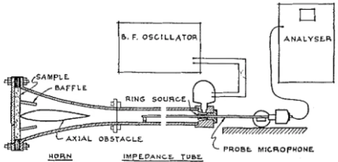
T o test the practicability of the method, use was made of an available exponential horn of circular i - cross section having mouth and throat diameters of 112 inches and 2$ inches and a length of about 32
2
inches. This was coupled to an impedance tube 2 t U inches in diameter by 40 inches long, which follows O 4 fairly closely the design of R. A. S c o t t . T h e associated
apparatus is shown schematically in Fig. 2. In
d) 0 2
Using a rigid termination on the horn mouth, the characteristic horn frequencies were determined by
noting the frequencies for which there was zero phase 0
2 0 0 1000 3000
shift at the throat (i.e., for which the first minimum was F R C Q U L N C Y - C Y C L L S / S E C .
one quarter of a wavelength from the end of the FIG. 5. Comparison of absorption coefficients obtained by horn and by direct impedance tube measurements, on a sample of R. A. Scott, Proc. Phys. Soc. (London) 58, 253 (1946). 2-inch Fiberglas Type PF.
506 T . D . N O R T I - I W O O D A N D H . C . P E T T I G R E W frequencies below about 1000 cycles. For work above
this frequency it was found necessary to introduce baffles in the mouth section to prevent a radial resonance a t the face of the sample. An additional improvement was obtained by introducing an axial obstacle to increase the axial path length and produce a better approximation to a plane wave a t the mouth. I t was then possible to get good agreement between the two methods up to about 3000 cycles. Absorption data obtained for three materials covering a wide range of absorption coefficients are shown in Figs. 3, 4, and 5.
In addition to the above program, an extension was added to the horn to adapt it to samples 12 inches square. This led to a rather abrupt change in horn section and resulted in discrepancies a t some frequencies
above 2000 cycles. However, no serious new problems were introduced, and useful measurements are being made up to this frequency. This makeshift assembly will shortly be replaced with a new horn, now being built, which terminates properly in a 12-inch-square mouth. I t is expected that satisfactory measurements up to about 3000 cycles will then be obtainable.
The primary aim to date has been the measurement of the normal-incidence absorption coefficients, in order to meet a specific requirement. A few measure- ments of acoustic impedance have been made and these agree well with impedance-tube data. The impedance problem will be examined more carefully after a routine for the absorption measurements has been established.