Study of the electronics architecture for the mechanical stabilisation of the quadrupoles of the
CLIC linear accelerator
This article has been downloaded from IOPscience. Please scroll down to see the full text article. 2010 JINST 5 C11014
(http://iopscience.iop.org/1748-0221/5/11/C11014)
Download details:
IP Address: 91.179.189.152
The article was downloaded on 18/01/2011 at 14:20
Please note that terms and conditions apply.
View the table of contents for this issue, or go to the journal homepage for more Home Search Collections Journals About Contact us My IOPscience
2010 JINST 5 C11014
PUBLISHED BYIOP PUBLISHING FORSISSA
RECEIVED: October 13, 2010 ACCEPTED: October 22, 2010 PUBLISHED: November 25, 2010
TOPICALWORKSHOP ONELECTRONICS FORPARTICLE PHYSICS 2010,
20–24 SEPTEMBER2010, AACHEN, GERMANY
Study of the electronics architecture for the
mechanical stabilisation of the quadrupoles of the
CLIC linear accelerator
K. Artoos, C. Collette, P. Fernandez Carmona,1M. Guinchard, C. Hauviller,
S. Janssens, A. Kuzmin and A. Slaathaug CERN,
1211 Geneva 23, Switzerland
E-mail:pablo.fernandez.carmona@cern.ch
ABSTRACT: To reach a sufficient luminosity, the transverse beam sizes and emittances in future
linear particle accelerators should be reduced to the nanometer level. Mechanical stabilisation of the quadrupole magnets is of the utmost importance for this. The piezo actuators used for this purpose can also be used to make fast incremental orientation adjustments with a nanometer resolution. The main requirements for the CLIC stabilisation electronics is a robust, low noise, low delay, high accuracy and resolution, low band and radiation resistant feedback control loop. Due to the high number of controllers (about 4000) a cost optimization should also be made. Different architectures are evaluated for a magnet stabilisation prototype, including the sensors type and configuration, partition between software and hardware for control algorithms, and optimization of the ADC/DAC converters. The controllers will be distributed along the 50 km long accelerator and a communication bus should allow external control. Furthermore, one might allow for an adaptive method to increase the S/N ratio of vibration measurements by combining seismometer measurements of adjacent magnets. Finally a list of open topics, the current limitations and the plans to overcome them will be presented.
KEYWORDS: Detector grounding; Detector control systems (detector and experiment monitoring
and slow-control systems, architecture, hardware, algorithms, databases); Special cables; Data acquisition concepts
2010 JINST 5 C11014
Contents
1 Introduction 1
2 Current prototype setup 1
3 Noise, signal and resolution study 2
3.1 ADC/DAC resolution 4
3.2 Noise budgeting 4
4 Stabilisation and positioning achievements 4
5 Final architecture study 5
5.1 Timing analysis 5
6 Conclusions 6
1 Introduction
In the Compact Linear Collider (CLIC) currently under study, electrons and positrons will be ac-celerated in two linear accelerators to collide at the interaction point with energy of 3 TeV [1]. To reach the design luminosity 5.9 × 1034cm−2s−1 of CLIC, the transverse beam dimensions at the interaction point should be 1 nm in vertical and 45 nm in the horizontal direction. For this purpose, about 4000 modules will contain Main Beam Quadrupoles (MBQ) that need to be mechanically stabilised to the nanometer level. The fully active stabilisation system is based on broadband seis-mometers and piezo actuators. The adopted stabilisation strategy is described in [2]. At this level of stability, the reduction of all the different noise sources is critical. This paper investigates some of them, e.g. sensor noise, cable noise and discretisation noise. Other critical factors like the reso-lution, required latency, control architecture and hardware limitations are also briefly addressed.
2 Current prototype setup
The components of the stabilisation system are currently tested in different prototype set-ups rang-ing from a scaled srang-ingle degree of freedom (d.o.f.) with low mass to a two d.o.f. system with equivalent mass (see figure 1). The scaled single d.o.f. system allows to study the control loop with a single sensor and a single piezo actuator while confirming the choice of the mechanical components. The increase of d.o.f. and hence number of sensors and actuators allows to evaluate the requirements on software and hardware for increased number of channels with respect to la-tency and performance. The vibrations of the magnet are measured with broadband seismometers GuralpCMG 6T that measure absolute velocity. In order to control the magnet vibrations a point
2010 JINST 5 C11014
Figure 1. Setup with 2 d.o.f. stabilization.
per point low latency real time controller was implemented. Due to the early stage of the design, a flexible, generalist configuration was chosen, based on National Instruments PXI. The heart is a PXI-8106RT with a 2.16 GHz dual core processor and 1 GB of memory. The acquisition and response generation system is based on M series cards, with 18 bit ADC and 16 bit DAC channels. The position feedback is done with piezoelectric P-225.1S actuators, driven by a PI E-508 amplifier.
3 Noise, signal and resolution study
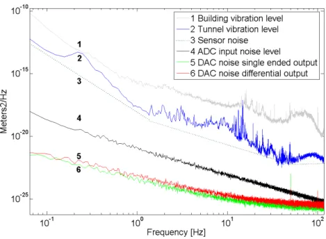
Due to the radiation and strong magnetic fields expected close to the magnets, where the sensors are located, the digital conversion has to be done from a distance, currently of 5 meters. This leaves a long cable path exposed to EM interferences. In addition to that acquisition and signal generation electronics introduce extra noise. The noise and signal curves measured are displayed in figure2. Curves 1 and 2 are measurements in a building and a tunnel at CERN. Curve 3 is sensor noise extracted from comparing two sensor signals under the same excitation. Curve 4 shows ADC noise: ϕADC ≈10
−22
f2 m2/Hz which originates from a voltage white noise, gain corrected and
integrated to translate from the velocity sensor output to the required displacement. It was extracted by placing a low noise input load equivalent to the sensor output impedance at the ADC input. Curves 5 and 6 represent DAC noise in single ended and differential mode, generated by sending a null output to a spectrum analyzer with an impedance similar to the actual load. They show a 1/f + white noise pattern: ϕADC≈10
−23
f + 10
−25m2/Hz with 50 Hz harmonics peaks that are lower
in differential mode. One can see that DAC noise against vibration SNR is at least 13 dB, and for ADC it is 20 dB. It has also been studied that the input vibration signal has a random nature.
Having characterized the expected noise from the acquisition electronics, the main focus is EM interferences and the power supply of the instrumentation. Optimised custom cables were created using separate ways for data and power, each with braiding of tinned copper wires shielding. Differential data channels go twisted in pairs with conductor area of 0.25 mm2and an average of 1 twist per cm. The improvement against single copper parallel lines used in previous setups is shown in figure3.
In order to minimize EM and ground conduction noise the shields of all components are con-nected to ground, with the exception of the vibration sensors which have by design the metallic
2010 JINST 5 C11014
Figure 2. Noise and signal power spectral density curves, expressed in m2/Hz.
Figure 3. Power spectral density curves of sensors comparing different cables, expressed in m2/Hz.
case internally connected to 0 V. Shielded twisted cable was selected over coaxial due to the low bandwidth of the signals. The beneficial self inductance effect that isolates a coaxial cable only starts above tens of kHz [3]. All the shields are only connected to the ground in one extremity of each cable. Typically conduction noise is higher than the EM interference protection given by self coupling in case of connecting the shield to both extremities of lines at low frequency [4]. The grounding of the shielding is always connected following a tree structure in order to avoid ground loops. For the quality of the general power supply a line conditioner with automatic volt-age regulator and AC surge suppressor Model TripLite LR2000 was used before all equipment in the setup.
As the sensor has been identified as the main source of noise, alternatives like in-sensor digi-talisation and frequency modulation will be evaluated together with providers in the future.
2010 JINST 5 C11014
Figure 4. Closed loop Block diagram of the system studied, including noise.
3.1 ADC/DAC resolution
With positioning requirements of steps of tens of nanometers in a range of 15 µm, and a required stabilisation sensibility of 0.1 nm, the dynamic range of the output DAC must be at least 0.1e−915e−6 = 150e3 which is equivalent to 17.2 real bits. As for the ADCs, seismometers measure velocity with a sensitivity of 2 kV/m/s in a bandwidth from 30 s to 100 Hz. The smallest measurable displacement will depend on the frequency at which it is measured as it is a velocity measurement. Furthermore, the amplitudes of the ground motion in a typical accelerator environment in an underground tunnel decrease with frequency as shown in figure2. The smallest voltage signals received by the ADCs are on the range of 20 µV. It has to be kept in mind that positioning and stabilisation are not performed at the same time, so the dynamic range can stay smaller than for the DAC. Also careful noise budgeting must ensure an equilibrated setup, with input ADC noise lower than both output DAC and intrinsic sensor noise levels. To be developed is a custom ADC/DAC system with the required resolution and noise levels, taking into account rack space restrictions and cost limitations. 3.2 Noise budgeting
This section is dedicated to study the influence of the instrumentation noise on the performances of active stabilisation with a mathematical model. Figure4shows the closed loop Block diagram of the system studied, showing the different sources of noise. G represents the mechanical plant and K the control gain.
In this figure, n1includes the measurement noise, nx plus the noise at the input of the control
unit, nin, such as n1= nx + nin. These two noise sources are considered statistically independent,
therefore Φn1= Φnx+ Φnin, while n2is the noise at the output of the controller.
The noise n transmitted at the output, resulting from the feedback operation, is found from figure4: n = -(n + n1)KG - n2G. As n1and n2are statistically independent, we get Φn= |SKG|2Φn1+
|SG|2
Φn2= Φ1+ Φ2where S = 1/ (1 + KG) is the sensitivity function. By this means are be able
to identify the critical noise sources and their impact at different points.
4 Stabilisation and positioning achievements
The importance of clean power supplies, adequate selection of cables, proper grounding and shield-ing and careful routshield-ing and placement of sensitive elements in relation to noise sources becomes clear by comparison of stabilisation results before and after the improvement of the cabling. Figure5 shows the same stabilisation experiment on the single d.o.f set-up in the TT1 tunnel at
2010 JINST 5 C11014
Figure 5. RMS integrated curves of vibration comparing original sensor cabling and new setup.
Figure 6. Control architecture options.
CERN during a night test using original cables and the presented ones. Vibration is successfully reduced to 0.63 nm integrated at 1 Hz, from a ground vibration of 2.05 nm, compared to 0.97 nm from 1.67 nm with the previous setup.
5 Final architecture study
Two control architectures are under evaluation for the CLIC magnet nano-stabilisation as shown in figure6. A first option is a distributed system in which a control module is located in the tunnel by each magnet, and working quasi independently, with communication with a central control and possibly inter-module. A second option is to minimize the number of components located by the magnet, with only sensors, actuators and some transducers and to send all information over a fast network to a central control mainframe. Most of the subsystems in CLIC are following the later approach; however the real time timing constrains might in the end impose the first choice. The final configuration of the local electronics is still to be studied.
5.1 Timing analysis
Using Labview Real Time analysis tool the delay from data acquisition to response generation has been measured to be 43 µs [5]. In order to evaluate the impact of the latency on stabilisation per-formance, an artificial delay is placed in the control loop. Setting the current setup as a reference 100% of the stabilisation performance under typical lab conditions, the delay is gradually increased
2010 JINST 5 C11014
Table 1. Relation between Performance and Delay.
Delay Performance 43µs 100% 80 µs 90% 90 µs 80% 100 µs 60% 130 µs 30%
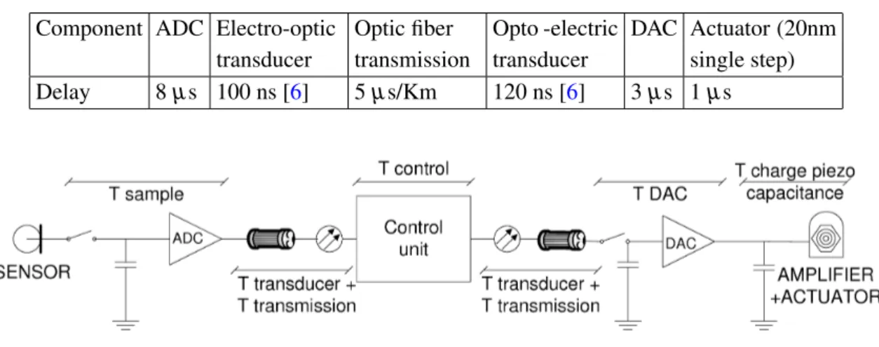
Table 2. Typical delay values for the components.
Component ADC Electro-optic transducer Optic fiber transmission Opto -electric transducer DAC Actuator (20nm single step) Delay 8 µs 100 ns [6] 5 µs/Km 120 ns [6] 3 µs 1 µs
Figure 7. Sensor to actuator signal path.
and the stabilisation factor measured (see table1). It is important to note that this is an experimen-tal result based on current set-up with the current control algorithm and badwidth. The eventual increase of bandwidth will make delay even more critical. Also these figures represent only 2 d.o.f. and set-ups with more d.o.f. will increase the number of channels and hence the delay. A model of the whole delay chain in the future distributed design is represented in figure7. Some typical catalog delay values for components are put together in table2to evaluate their relative impact to the overall delay. In particular it proves especially relevant the impact from a long optical link in the control loop, as in the case of a hypothetical minimum 1.5 Km distance from the tunnel to a control centre.
6 Conclusions
The detailed architecture of an active vibration controller for a particle accelerator has been de-scribed from the point of view of an electronic hybrid system. It has been shown the impact of different noise sources in the performance, and some strategies to reduce it by means of shielding, grounding and adequate choice of cables. The possibilities of central and distributed control archi-tectures were evaluated, together with the performance penalties due to delay and finally a model of the main delay sources was presented.
2010 JINST 5 C11014
Acknowledgments
The research leading to these results has received funding from the European Commission under the FP7 Research Infrastructures project EuCARD.
References
[1] J.P. Delahaye, Towards CLIC feasibility, proceeding of The 1st International Particle Accelerator Conference, IPAC10, Kyoto Japan, May 23–28 2010.
[2] C. Collette et al., Active quadrupole stabilisation for future linear particle colliders,Nucl. Inst. Meth. Phys. Res.A 621 (2010) 71.
[3] D.C. Smith, High frequency measurements and noise in electronic circuits, Springer, (1992). [4] E.B. Joffe and K.-S. Lock, Grounds for Grounding, Wiley-IEEE, (2010).
[5] A. Kuzmin, Real Time performance of CLIC stabilisation system, CERN EDMS 1095555. [6] Everlight Electronics Co. Ltd.,http://www.everlight.com.