HAL Id: lirmm-01221397
https://hal-lirmm.ccsd.cnrs.fr/lirmm-01221397
Submitted on 9 Oct 2019
HAL is a multi-disciplinary open access
archive for the deposit and dissemination of
sci-entific research documents, whether they are
pub-lished or not. The documents may come from
teaching and research institutions in France or
abroad, or from public or private research centers.
L’archive ouverte pluridisciplinaire HAL, est
destinée au dépôt et à la diffusion de documents
scientifiques de niveau recherche, publiés ou non,
émanant des établissements d’enseignement et de
recherche français ou étrangers, des laboratoires
publics ou privés.
Cable-Suspended Parallel Robot
Marc Gouttefarde, Jean-François Collard, Nicolas Riehl, Cédric Baradat
To cite this version:
Marc Gouttefarde, Jean-François Collard, Nicolas Riehl, Cédric Baradat. Geometry Selection of
a Redundantly Actuated Cable-Suspended Parallel Robot. IEEE Transactions on Robotics, IEEE,
2015, 31 (2), pp.501-510. �10.1109/TRO.2015.2400253�. �lirmm-01221397�
Geometry Selection of a Redundantly Actuated Cable-Suspended Parallel Robot
Marc Gouttefarde,Member, IEEE,Jean-Franc¸ois Collard, Nicolas Riehl and C´edric Baradat
Abstract—This paper is dedicated to the geometry selection of a redun-dantly actuated cable-suspended parallel robot intended to manipulate heavy payloads over a wide workspace. Cable-suspended refers here to cable-driven parallel robots in a crane-like setting where all the cable drawing points are located on top of the base frame, gravity being used to keep the cables taut. Geometry selection consists in determining the relative positions of the cable drawing points on the base frame and of the cable attachment points on the mobile platform together with the cable arrangement between these two sets of points. An original performance index is introduced. It is defined as the maximum acceptable distance between the mobile platform geometric center and the center of mass of the set consisting of the platform and a payload. This performance index is of particular interest in heavy payload handling applications. Used within a two-phase geometry selection strategy, it yields a new cable-suspended robot geometry having a very large workspace to footprint ratio and able to handle heavy payloads. A large-dimension redundantly actuated cable-suspended robot was built in order to demonstrate these capabilities.
I. INTRODUCTION
This paper deals with cable-suspended parallel robots. As illus-trated in Fig. 1, this name refers here to cable-driven parallel robots whose cable drawing points are all located above the mobile platform. A well-known 6-degree-of-freedom (DOF) cable-suspended robot is the NIST ROBOCRANE [1]. As opposed to fully-constrained cable-driven parallel robots such as the FALCON [2], the weight of the mobile platform (and payload) is necessary to keep the cables taut. The part of the workspace located below the mobile platform is free of cables making this type of cable robot attractive for applications like heavy payload handling. In the present work, we focus on 6-DOF redundantly actuated cable-suspended robots and, hence, we do not consider under-constrained robots [3] which are driven by less cables than DOF. Additionally, unlike in [4], [5], the cable drawing points are supposed to be fixed (no mobile bases).
The mobile platform of a cable-driven parallel robot is connected to winches by means of a set of cables. The cables are attached to the mobile platform and exit from the robot fixed base at some points, referred to as the cable drawing points. The relative positions in space of the cable drawing points define the base geometry. We define the platform geometry as the relative positions of the cable attachment points on the mobile platform. Moreover, a cable-driven
parallel robot geometry is defined as the set consisting of the base geometry, the mobile platform geometry and the cable connections (or arrangement) between them.
The selection of a cable-driven parallel robot geometry is a funda-mental choice because it strongly influences the robot performances. Most of the previous works dealing with geometry selection are dedicated to fully-constrained cable-driven parallel robots. In several papers [2], [6]–[11], the geometry selection process itself is either not discussed or not the result of a systematic methodology. On the
Marc Gouttefarde is with the Laboratoire d’Informatique, de Robotique et de Micro´electronique de Montpellier (LIRMM), CNRS - Universit´e Montpellier 2, 161 rue Ada, 34095 Montpellier Cedex 5, France (e-mail: [email protected]).
Jean-Franc¸ois Collard is with the Center for Research in Mechatronics, Universit´e catholique de Louvain, 2 Place du Levant, 1348 Louvain-la-Neuve, Belgium (e-mail: [email protected]).
C´edric Baradat is with TECNALIA France, MIBI, 672 rue du Mas de Verchant, 34000 Montpellier Cedex 2, France (e-mail: [email protected]).
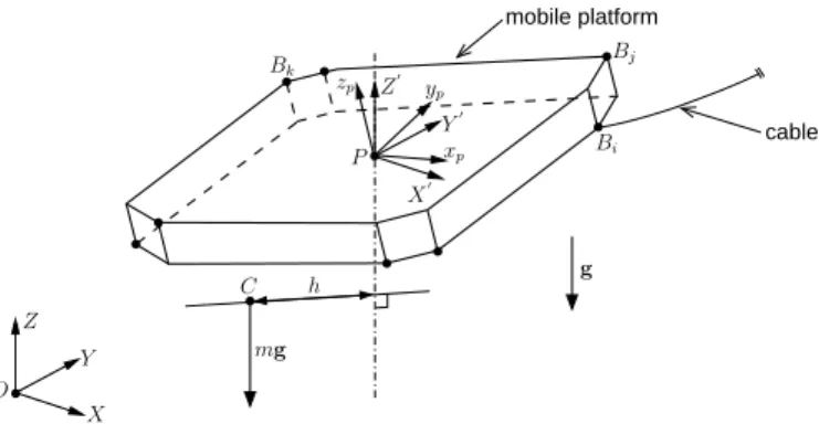
Fig. 1. Sketch of a cable-suspended parallel robot.
contrary, the use of various optimization techniques are presented in [4], [5], [12]–[15]. The main criteria are the wrench-closure workspace, or other types of wrench-feasible workspaces [16], and avoidance of cable collisions. An initial geometry is usually required to start the optimization process making the exploration of the design space usually limited. Other fully-constrained cable robot geometries were obtained by means of geometric or other ad hoc considerations [17], [18]. The early work by Tadokoro et al [19] is an exception. Indeed, unlike in the aforementioned papers, the combinatorial nature of the possible cable connections between some given base and platform geometries is explicitly considered. It enables a much wider variety of fully-constrained cable robot geometries to be explored. Recently, in the context of the synthesis of differential cable-driven parallel robots, all possible arrangements of cable segments in a differential were studied in [20].
The geometry selection of cable-suspended robots has been less discussed than that of fully-constrained robots. In [1], the geometry of the NIST ROBOCRANE is introduced as an upside-down Gough-Stewart platform with triangular base and platform. The influences of some geometric parameters on the static workspace and on the global condition index of such 6-6 cable-suspended parallel robots are studied in [21]. The dimensional design of the 6-cable suspended parallel manipulator of FAST is reported in [22]. A less conventional 6-cable suspended robot geometry is presented in [23] for a particular application. In all these works, a limited number of geometric parameters is considered and all possible cable connections are not explicitly studied. Consequently, the set of investigated cable-suspended robot geometries is not very large.
None of the aforementioned previous works deals with the ge-ometry selection of redundantly actuated cable-suspended parallel robots, which is the topic of the present paper. A two-phase geometry selection methodology is considered. Inspired by [19], the first phase of this methodology consists in testing a very large number of possible cable connections between various base and platform preselected geometries. The second phase aims at refining the result of the first phase using standard gradient-based optimization. While this two-stage methodology is not particularly novel, the result of its application to redundantly actuated cable-suspended parallel robots is the main contribution of this paper. Indeed, it yields a new
cable-suspended robot geometryhaving a very large workspace to footprint ratio and able to manipulate heavy payloads. To demonstrate these capabilities, a large-dimension 8-cable 6-DOF robot was built in the framework of a research project called CoGiRo.
The second contribution of this paper is a particular feasibility analysis. A mobile platform pose is said to be wrench-feasible when a required wrench set is entirely contained within the set of wrenches that the cables are able to apply, called the available
wrench set [24]. The particularity of the analysis proposed in this paper lies in the definition of the required wrench set. In previous works, e.g. [24]–[27], this set is a hyperellipsoid, a hyperrectangle or it is reduced to a unique wrench. Focusing on heavy payload handling tasks, the required wrench set introduced in the present work corresponds to the wrenches that permit to balance the total weight of the platform and the payload. When both the mass and the center of mass position are variable, this required wrench set is a truncated cone. The analysis of the conditions under which this cone is completely contained within the available wrench set leads us to a new performance index defined as the maximum acceptable horizontal distance between the mobile platform geometric center and the center of mass of the set consisting of the platform and the payload. This index is of particular interest in applications involving heavy payload manipulations.
The paper is organized as follows. The particular wrench-feasibility analysis and the resulting new performance index are introduced in Section II. The two-phase geometry selection methodology is summarized in Section III. The application of this methodology to the geometry selection of a 6-DOF cable-suspended parallel robot driven by 8 cables is presented in Section IV.
II. WRENCH-FEASIBILITYANALYSIS
In this paper, the evaluation of cable-suspended parallel robot geometries relies on their quasi-static behavior. Compared to the static ones, the forces and moments due to the mobile platform dynamics are neglected. Our goal is to evaluate the ability to handle payloads that may not be centered with respect to the platform reference point. To this end, we introduce an original performance index defined as the maximum acceptable horizontal distance between the platform
reference point and the center of mass of the set composed of the platform and a payload. Subsections II-A and II-B present the usual static equilibrium equations and wrench feasibility analysis, respec-tively. Subsection II-C introduces the particular required wrench set considered in this paper. Finally, Subsection II-D shows how the aforementioned original performance index can be computed.
A. Static modeling of cable-suspended parallel robots
Neglecting the mass of the cables, the static equilibrium of a 6-DOF cable-driven parallel robot mobile platform is given by [9], [28]
W τ+ fe= 0 (1)
where W is the so-called wrench matrix of dimension 6 × n, n denotes the number of cables (n ≥ 6 in this paper), τ is the column vector containing the cable tensions and fe is the external wrench
applied to the platform at its reference point.
Cable tensions are subjected to minimal and maximal admissible values. The maximal value τmax is necessary in order to take
into account mechanical limits (e.g. cable breaking load, or force sensor maximum load). The minimal value τmin must be
non-negative because the cables cannot push on the mobile platform. For cable-suspended parallel robots, since the cables are not acting antagonistically on the mobile platform, the minimal tension τmin
should be set to a small value or to zero.
B. Wrench feasibility analysis
Following the analysis proposed in [24], for a given pose (position and orientation) of the platform, the available wrench set (AW) is defined as the set of wrenches f that the cables can generate at the mobile platform reference point
AW = {f = W τ | τmin≤ τ ≤ τmax} (2)
where the components of the n-dimensional vector τmin are all
equal to the minimal admissible cable tension τmin ≥ 0 and all
the components of τmax are equal to τmax. Besides, the required
wrench set(RW) is the set of wrenches that the cables must exert on the platform to complete a task. The exact definition of RW is directly related to the application or task(s) at hand. A mobile platform pose is said to be wrench-feasible when RW⊆ AW, which means that the cables can generate any wrench in RW while satisfying the constraints τmin≤ τ ≤ τmax.
Even for geometrically simple RW, testing wrench feasibility by means of (2) is generally an issue. However, being the image of the hypercube τmin≤ τ ≤ τmax under the linear map represented by
matrix W, AW is a convex polytope and can thus be represented as the solution set of a system of linear inequalities [29]
AW= {f | Cf ≤ d} (3)
Testing wrench feasibility by means of (3) is generally straightfor-ward. For example, when RW is defined as a hypercube, RW⊆ AW if and only if all hypercube vertices fvsatisfy Cfv≤ d. The difficulty
lies in the determination of matrix C and vector d. They can be obtained efficiently by means of the co-called hyperplane shifting method introduced in [25]. Let us briefly present this method being given that a comprehensive description can be found in [25], [30].
For a6 × n wrench matrix W (6 DOF and n ≥ 6 cables), each combination of 5 linearly independent columns wi1, . . . , wi5 of W
provides two lines of C, say cTk and cTl. The line cTk is given by
ck = cI = null (MI), where cI = null (MI) denotes a vector
spanning the nullspace of the5 × 6 matrix MI= [wi1, wi2, . . . , wi5]
T
(4) and I denotes the index set {i1, . . . , i5} ⊂ {1, . . . , n}. The other
line is cTl = −cTI. The total number Nh of lines of matrix C is
equal to twice the number of possible combinations of five linearly
independent columns of the wrench matrix W.
Complementing the work done in [25], it was shown in [30] that the two elementsdk and dlof vector d corresponding to the lines
cTk and c T
l of matrix C are given by
dk = X i∈I+ τmaxcTIwi+ X i∈I− τmincTIwi (5) dl = − X i∈I− τmaxcTIwi− X i∈I+ τmincTIwi (6) whereI+ and I−
are the subsets of{1, . . . , n} defined as I+ =ni | cT Iwi> 0 o andI− =ni | cT Iwi< 0 o (7) In the sequel, the line cTj of matrix C is denoted as follows
cTj =
h
cjfx cjfy cjfz cjtx cjty cjtz
i (8) wherefx,fy,. . ., tz stand for the force and moment components of
a wrench f= [fx, fy, fz, tx, ty, tz]T.
C. Required wrench set
The originality of the wrench-feasibility analysis conducted in this paper comes mainly from the RW introduced in this subsection. This RW is the wrench set that the cables must apply to the mobile platform in order to balance the platform and payload weight for a set of possible masses and positions of the center of mass (CoM). This RW is notably relevant in cable-driven parallel robot applications involving the manipulation of heavy payloads of various sizes and weights. Indeed, in such applications, the CoM of the set composed of the robot mobile platform and a payload is generally not coincident
cable mobile platform mg h X Z O g P xp Y Bi Bj Bk Y′ X′ Z′ zp C yp
Fig. 2. Cable-suspended parallel robot mobile platform—Points Biare the
cable attachment points, P is the platform reference point (“geometric center”) and C is the platform and payload CoM. The reference frame(O, X, Y, Z) is fixed and its axis Z is vertical. (P, xp, yp, zp) is a local frame attached
to the platform. The frame(P, X′, Y′, Z′) is centered at P but it has the same orientation as the fixed reference frame, i.e., X′ = X, Y′ = Y and Z′= Z. Axis Z′ is thus vertical.
with the mobile platform reference point P and its position can change from one payload to another.
In the sequel, we refer to the platform reference pointP as the platform geometric center. The CoM of the set consisting of the mobile platform and a payload is denoted C. For a given platform orientation, as illustrated in Fig. 2,C is usually not located on the ver-tical line passing through pointP . The (horizontal) distance between C and this vertical line is denoted h. The sum of the platform and payload masses is denotedm whereas g = 9.81 ms−2
is the gravity acceleration. In a frame having a vertical z-axis and whose origin is the platform geometric center P , e.g., the frame (P, X′, Y′, Z′) shown in Fig. 2, the wrench f = [fx, fy, fz, tx, ty, tz]T that the
cables must apply to balance the platform and payload weights is fx= fy= tz = 0, fz= mg and
q t2
x+ t2y= mgh (9)
where fx, fy and fz are forces along the X
′
, Y′ and Z′ axes, respectively, and tx,ty andtz are moments about these axes. Only
the horizontal distanceh is relevant since f is not influenced by the vertical position of the CoMC. Note that, for a given position of C in the local platform frame, the distanceh depends on the platform orientation, i.e., on the angle betweenzp and the vertical axis.
Let us consider that the position of C and the mass m are not exactly known and/or subjected to changes in such a way that 0 ≤ h ≤ r and mmin ≤ m ≤ mmax wherer, mmin and mmax are
positive scalars. Typically, mmin is the mass of the empty mobile
platform andmmaxis the sum of the platform and heaviest payload
masses. Such a situation leads to a set of possible wrenches at point P that the cables must be able to apply to the set platform-payload to balance their total weight. This wrench set is the RW considered in this paper. It is defined as follows
RW = {f | fx= fy= tz= 0, mming ≤ fz≤ mmaxg,
0 ≤qt2
x+ t2y≤ mgr} (10)
In the space of wrenches applied by the cables at the platform geometric center P , this RW is a truncated cone embedded in the three-dimensional subspace fx= fy= tz = 0, as shown in Fig. 3.
It is apparent in the figure, and not difficult to prove, that this RW is the convex hull of its lower discL and upper disc U, where
L = {f | fx= fy= tz= 0, fz = mming, 0 ≤qt2 x+ t2y≤ mmingr} (11) mmaxgr mmingr ty tx fz Truncated cone Lower disc mming mmaxg Upper disc
Fig. 3. RW considered in this paper: A truncated cone.
U = {f | fx= fy= tz= 0, fz= mmaxg,
0 ≤qt2
x+ t2y≤ mmaxgr} (12)
The available wrench set AW being also a convex set, a given mobile platform pose is wrench-feasible, i.e. RW⊆ AW, if and only if both the lower discL and the upper disc U of RW are entirely contained within AW.
D. Performance index definition
In this work, we are interested in the maximum value rmax ofr
such that RW defined in (10) is fully included in AW. For a platform and payload total mass comprised betweenmminandmmax,rmax
corresponds to the maximum acceptable horizontal distance between the platform geometric centerP and the CoM C. According to the definition of AW, admissible means that each cable tension lies in the non-negative interval[τmin, τmax]. For a given pose of the mobile
platform,rmaxindicates to which extent the CoM can be shifted with
respect to the platform reference pointP while keeping admissible cable tensions. It will be used in Section III as a performance index to evaluate and optimize cable-suspended parallel robot geometries. Referring to Section II-C, RW⊆ AW if and only if both the lower discL and the upper disc U of RW are entirely contained in AW. Consequently,rmaxis the largest value ofr such that both L and U
are fully included in AW. Let us first consider the case of the upper discU. As proved in the Appendix, the maximum value r1ofr such
thatU is fully included in AW is equal to r1= min j r1,j= minj dj mmaxg − cjfz q c2 jtx+ c 2 jty (13)
The case of the lower discL is similar with mminin place ofmmax,
i.e., the maximum valuer2ofr such that L is fully included in AW
is equal to r2= min j r2,j= minj dj mming− cjfz q c2 jtx+ c 2 jty (14)
Therefore, for a given pose of the platform, the maximum acceptable horizontal distance between the platform geometric centerP and the platform and payload CoMC, i.e. the largest value of r such that RW⊆ AW, is given by
rmax= min
i=1,2ri= mini,j ri,j (15)
with ri,j= dj mig − cjfz q c2 jtx+ c2jty , i = 1, 2, and j = 1, . . . , Nh (16)
III. OPTIMALGEOMETRYSELECTIONMETHODOLOGY
A. Phase 1: Exploration
The first phase of the geometry selection methodology used in this paper consists in generating and testing a discrete but large number of possible cable-driven parallel robot geometries. In contrast to a local optimization, this first phase aims to explore “globally” the very wide space of possible robot geometries in order to find a good starting point for the optimization performed in the second phase (Section III-B). To this end, a strategy divided into four subsequent steps is summarized in this section.
1) Step 1: User defined parameters: The number of mobile platform DOF and the number of cables are first defined. In this paper, 6-DOF parallel robots driven byn = 8 cables are considered. The user also defines a number of base and platform geometry types. A base (resp. platform) geometry type is defined as a set of distinct
pointsat which the cables exit from the fixed base (resp. are attached to the mobile platform) and a set of dimensional parameters defining the relative positions between these distinct points. For instance, in Fig. 5(a), four distinct cable attachment points define a rectangular mobile platform geometry type whose dimensional parameters are the edge lengthsL1 and L2. For each dimensional parameter of the
base and platform geometry types, a discrete set of possible values is defined by the user.
A base (resp. platform) geometry is fully specified by a base (resp. platform) geometry type together with particular values assigned to each of its dimensional parameters. These values are taken among the discrete set of possible ones.
The base and platform geometry types may have some symmetry properties, in which case the corresponding symmetry rules are also specified. In many applications, the prescribed workspace is symmetric. Moreover, symmetric cable-driven parallel robot geome-tries should possess more homogeneous performances across their workspace. In this paper, each point of a geometry type has a sym-metric point with respect to thez-axis, i.e., points having coordinates (x, y, z) and (−x, −y, z) are symmetrical to each other. Note that the z-axis of the local frame attached to the mobile platform is vertical when the platform lies in its reference orientation. Symmetries with respect to this z-axis are considered because we are dealing with cable-suspended parallel robots which rely on gravity to keep the cables in tension.
Additionally, a prescribed workspace is defined together with a discrete set of poses defining a discretization of this workspace. Other necessary modeling and performance criterion related parameters are finally to be specified. In this paper, only the minimum and maximum mass valuesmminandmmaxneed to be defined.
2) Step 2: Generation of cable arrangements: All possible cable arrangements between the base and platform geometry types defined in Step 1 are generated. The only information needed is the number of distinct points of these geometry types, as well as the potential symmetry properties.
Let us consider thenbdistinct points of a given base geometry type
and the np distinct points of a platform geometry type. The cable
arrangements between these two sets of points can be represented by matrices ASof dimensionnb× np. The components of ASare such
that ASi,j = 1 if point i of the base geometry type is connected
to pointj of the platform geometry type, and ASi,j = 0 otherwise.
Moreover, in order to generate valid cable arrangements, the two following rules must also be respected.
1) All base points must be used: The sum of the components in each row of ASmust not be zero.
2) All platform points must be used: The sum of the components in each column of ASmust not be zero.
In this step, all such matrices ASare generated. For instance, when
n = nb= np= 8, the total number of matrices AS is8! = 40 320.
Symmetry properties can also be reflected in the generation of cable arrangements. In this paper, as introduced in Section III-A1, point i of a base (resp. platform) geometry type has a symmetrical point. Let the latter be numbered nb− i + 1 (resp. np− i + 1).
Then, in order to reflect this symmetry into the cable arrangements, we only keep the matrices AS such that if ASi,j = 1 then
ASnb−i+1,np−j+1= 1. For example, in the case n = nb= np= 8,
the number of symmetric valid cable arrangements is equal to384.
3) Step 3: Generation of cable-driven parallel robot geometries:
One cable-driven parallel robot geometry is obtained for each possible combination of the following three elements.
• A base geometry type and values of its dimensional parameters
chosen among the discrete set of values defined in Step 1.
• A platform geometry type and values of its dimensional
param-eters taken among the discrete set of values defined in Step 1.
• A cable arrangement between these base and platform
geome-tries, taken among the arrangement set generated in Step 2. Each such combination defines a cable-driven parallel robot geometry consisting of the cable drawing point positions in the fixed reference frame, the cable attachment point positions in the platform local frame and the cable arrangement between these two point sets.
4) Step 4: Performance evaluation and collision detection: All the cable-driven parallel robot geometries generated in Step 3 are considered in turn. For each one of them, at each pose of the discretized prescribed workspace defined in Step 1, the absence of cable-cable collisions is tested and the value of rmax (Eq. (15)) is
computed. The performance index of the geometry at hand is defined as the minimum value ofrmax over all the poses of the discretized
prescribed workspace. Among the cable-driven parallel robot geome-tries having no collision between the cables, the geometry having the largest performance index is considered to be the best one. The cables being assumed to be straight line segments (cable mass is neglected), the absence of collision between two cables is tested by computing the distance between them [31], [32].
A rough discretization of the prescribed workspace should be used in order to get a reasonable computation time. Consequently, the performances and avoidance of cable-cable collisions should be ascertained at the end of the geometry selection procedure (after the second phase described in Section III-B), e.g. by means of a fine discretization or of interval analysis.
B. Phase 2: Optimization
The second phase of the optimal geometry selection methodology is briefly introduced in this section. By formulating a nonlinear optimization problem, we aim at locally refining the best cable-driven parallel robot geometry obtained in the first phase (Section III-A). The latter robot geometry is thus taken as the initial guess of a standard iterative gradient-based optimization algorithm.
1) Problem formulation: In this paper, optimizing a cable-driven parallel robot geometry consists in maximizing the maximum
accept-able horizontal distancermaxbetween the platform geometric center
P and the platform and payload CoM C (Eq. (15)) over all the poses of a discretized prescribed workspace. For all these poses, the avoidance of cable-cable collisions is formulated as a set of inequality constraints kcollision ≤ 0 as specified in Section III-B3. Hence, the
maximization problem considered here can be written as maximize min
i = 1, 2 j = 1, . . . , NhNp
ri,j (17)
over p∈ [pmin, pmax]
where ri,j is defined in (16),Nh is the number of inequalities in
Cf ≤ d (Eq. (3)) and Npis the number of poses in the discretized
prescribed workspace. Indexj refers here to both the inequalities in Cf ≤ d and the poses of the discretized prescribed workspace.
The vector p of optimization variables contains the coordinates of the position vectors ai= [aix, aiy, aiz]Tof the cable drawing points
(in the fixed base frame) and the position vectors bi= [bix, biy, biz]T
of the cable attachment points (in the mobile platform frame). It also contains an angleψ0which defines an offset of the platform reference
orientation about the verticalZ-axis of the base frame. The vectors of bound values pminand pmaxreport the extreme values of aiand
bi, which are computed from user defined bounds on the dimensional
parameters of the base and platform geometry types, as well as the extreme values−π and +π of ψ0.
In order to solve problem (17) using standard algorithms, it is written in the following equivalent form
minimize z (18)
subject to − arctan (ri,j) ≤ z,
i = 1, 2 and j = 1, . . . , NhNp
kcollision≤ 0,
over z ∈ R, p ∈ [pmin, pmax]
where, to improve the numerical behavior of the optimization solver, the values of ri,j have been scaled using the arctan function to
highlight the smallest values with respect to the largest ones. It is a large-scale optimization problem involving 6n + 2 variables and 2NhNp+ Nc inequality constraints, where Nc is the total number
of collision constraints. For instance, the geometry optimization of a 8-cable robot (n = 8, Nh = 2C85 = 112 [30]) evaluated over
27 positions in a given box (center, 8 vertices, 12 mid-edges and 6 mid-faces) for 2 orientation angles around the vertical axis (Np =
27 × 2 = 54) involves 6 × 8 + 2 = 50 variables and 2 × 112 × 54 + 1512 = 13 608 inequality constraints. The total number Nc= 1512
of collision constraints is obtained by multiplying the number of cable pairs byNp.
2) Derivatives of the performance criterion:The use of a gradient-based optimization algorithm requires the computation of the deriva-tives ofri,j with respect to (w.r.t) the design variables gathered in
vector p. According to (16), this computation amounts to calculating the derivatives of the components of vector d and matrix C (namely ofdj,cjfz,cjtx andcjty) w.r.t. to p. These components depend on p
via the wrench matrix W. The explicit expression of W in terms of the design variables p is well-known [9], [28] and the determination of its derivatives w.r.t. to p is straightforward. Moreover, referring to the hyperplane shifting method outlined in Section II-B, calculating the derivatives of d and C w.r.t. W amounts to computing the derivatives of cI = null (MI) w.r.t. W. The latter derivatives can
be obtained by two means. The first one consists in considering the singular value decomposition of MI and then in following the
procedure proposed in [33]. The second one is to use a determinant based expression of a nullspace spanning vector [34] and then apply the well-known formula of the derivatives of a determinant.
3) Collision avoidance constraints: Each collision avoidance in-equality constraint in (18) is based on the computation of the distance between two cables. In this paper, the cables are considered to be straight line segments. The distance between two segmentsLiandLj
must remain greater than the cable diameterδc(a small non-negative
value). Hence, the corresponding collision avoidance constraint is kcollision= δc− dist (Li, Lj) ≤ 0 (19)
This scalar constraint has to be fulfilled by all cable pairs in every platform poses of the discretized prescribed workspace. All the resulting constraints are gathered in vector kcollision.
In this work, the algorithm proposed in [32] has been used to compute the distance between two straight line segments and the derivatives of the collision avoidance constraints computed accord-ingly.
IV. GEOMETRYSELECTION OF ALARGECABLE-SUSPENDED ROBOT
This section reports the application of the two-phase optimal geometry selection methodology presented in Section III to the design of a cable-suspended parallel robot. The obtained geometry is new and provides effective performances across a very large workspace. Based on this result, a large cable-suspended parallel robot has been built in the framework of a research project called CoGiRo [35].
A. Input data
The cable-suspended parallel robot whose geometry is to be determined has 6 DOF and is driven by 8 cables.
1) Workspace dimensions: The inner volume of the fixed base structure is a box of dimensions 14.81 m× 10.81 m × 5.58 m (l × w× h). The prescribed constant-orientation workspace is defined by a scaling of this box: 2/3 of the length and 1/2 of the width and height. Its discretization consists of 27 positions (center, 8 vertices, 12 mid-edges and 6 mid-faces). The required platform rotations are about the vertical axis only, with a limited range of±π/12. To define the discretization of the prescribed workspace, five different angles in the range±π/12 were considered in Step 4 of Section III-A. In the local optimization problem of Section III-B1, the two extreme angles−π/12 and +π/12 were used.
2) Platform and payload masses and cable tensions: The mobile platform mass is mmin = 40 kg whereas the total mass of the
platform loaded up with the heaviest payload ismmax= 200 kg.
The cables are anti-rotation steel cables of diameter 4 mm. Accord-ing to the breakAccord-ing loads of various mechanical parts, the maximum admissible cable tensionτmaxis 5825 N (50% of the cable breaking
load). A small positive value should be chosen for τminto restrict
cable sagging. In this work,τmin= 20 N has been selected.
3) Base geometries: A unique fixed base geometry type is consid-ered. It is enclosed in the inner volume of the fixed base structure so that its dimensional parametersL, l and h, shown in Fig. 4, are set to 14.81 m, 10.81 m and 5.58 m, respectively. It consists of8 drawing points all located at the top as illustrated in Fig. 4. The relative positions between these 8 points are defined by distances ∆L and ∆l. Due to manufacturing constraints, ∆L and ∆l must both be com-prised between 255 mm and 425 mm. In phase 1 (Section III-A), all acceptable combinations of these bounding values were considered. In phase 2 (Section III-B),∆L and ∆l were left free between these bounding values.
4) Mobile platform geometries: We constrained the cable attach-ment points to be enclosed in a cube of side length 1 m. The considered platform geometry types are shown in Fig. 5 to 9 where2 to4 dimensional parameters L1toL4 are required depending on the
geometry type at hand. In the first phase of the geometry selection procedure (Section III-A), a discrete set of four values included in the interval [0.25, 1] (m) was considered for each parameter. The attachment point positions were left free within the one-meter side cube in the second phase (Section III-B).
1 2 3 4 5 6 7 8 replacements h x y z (a) 3D view ∆L ∆l L l x y (b) 2D top view
Fig. 4. Base geometry type parameterized by L, l, h,∆L and ∆l.
1 2 3 4 L1 L2 x y
(a) Rectangular platform
1 2 3 4 x y L1 L2 (b) Diamond platform Fig. 5. Two four-point platform geometry types parameterized by L1 and
L2.
B. Optimal geometry selection results
In the first phase (Section III-A), 1888 cable arrangements were generated, leading to 686080 different cable-suspended robot ge-ometries. The corresponding performance evaluation and cable-cable collision detection took 3.8 hours on a desktop computer (2.53 GHz, 3 Gb of RAM). The best geometry obtained is depicted in Fig. 10(a) and defined in Table I. Only the coordinates of points 1 to 4 are given since points 5 to 8 are symmetrical according to the rule specified in Section III-A. The platform geometry has 8 different attachment points located at the vertices of a parallelepiped. It comes from the spatial eight-point geometry type shown in Fig. 9.
The computation time of the second phase (Section III-B) was 25 minutes on the same computer (2.53 GHz processor). The resulting optimized geometry is shown in Fig. 10(b) and defined in Table II. Compared to the result of phase 1, it can be observed that the platform geometry is not a parallelepiped anymore and that the orientation offset ψ0 about the vertical axis is not negligible. The optimization
significantly improved the performance indexrmaxfrom 16.4 cm to
28 cm. Such a value of the maximum acceptable horizontal distance between the platform geometric center and platform and payload CoM provides a certain robustness in handling heavy payloads.
In the framework of a research project called CoGiRo [35], the novel geometry shown in Fig. 10(b) has been used to build a large cable-suspended robot. This geometry yields characteristics that largely outperform the initial requirements given in Section IV-A. Indeed, the prescribed constant orientation workspace was specified as 2/3 of the length and 1/2 of the width and height of the fixed
1 2 3 4 5 x y L1 L2
(a) Rectangular platform
1 2 4 3 5 x y L1 L2 (b) Diamond platform Fig. 6. Two five-point platform geometry types parameterized by L1and L2.
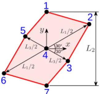
2 4 1 3 5 6 30° 30° L2 L1/2 L1/2 L3/2 L3/2 x y
(a) Planar platform
1 2 3 4 5 6 L1 L2 L3 x y z (b) Spatial platform
Fig. 7. Two six-point platform geometry types parameterized by L1, L2and
L3.
base inner volume which represents 16.6 % of this volume. The actual constant-orientation static workspace (set of feasible static equilibria) for the platform reference orientation and for m = 100 kg,τmax= 5825 N and τmin= 0 N occupies 77 % of the volume,
wherem denotes the sum of the mobile platform and payload masses. The projection on soil of this static workspace spans 78 % of the robot total footprint. Only small rotations about the vertical axis were initially required. The actual mobile platform orientation capabilities are much better. For instance, at 2 m above the ground in the middle of the workspace, the total orientation range about the vertical axisZ is 105◦
(−70◦
to+35◦
) and the orientation ranges about the horizontal X and Y axes are both of ±40◦
(taking into account cable collisions with the actual cube-shaped mobile platform shown in Fig. 11). With appropriate cable tension distributions, the mechanical design allows the robot to lift masses up tom = 300 kg across 77 % of the footprint and 75 % of the robot overall volume and up tom = 500 kg across 76 % of the footprint and 70 % of the robot overall volume.
V. CONCLUSION
This paper presented the geometry selection of a large redun-dantly actuated cable-suspended parallel robot. Based on a partic-ular wrench-feasibility analysis, an original performance index was defined as the maximum acceptable horizontal distance between the mobile platform reference point and the platform and payload center of mass. It is of particular interest in applications involving heavy payload manipulations over large workspaces. Used within a two-phase geometry selection strategy, it yielded a new and efficient geometry for 6-DOF cable-suspended robots driven by 8 cables. The main merit of this geometry is a very large workspace to footprint ratio. Based on this result, a large 6-DOF cable-suspended robot was built. Its performances demonstrate the relevance of redundant actuation for cable-suspended parallel robots and of the particular robot geometry disclosed in this work.
A quasi-static modeling was used in this paper since static forces and moments were considered to be predominant. Moreover, the cable mass was neglected. The extension to cases in which the mobile platform dynamics and the cable mass have to be taken into account is part of our ongoing work.
2
4
1
3
5
6
7
30° 30° PSfrag L1/2 L1/2 L2 L3/2 L3/2 x yFig. 8. Seven-point planar platform geometry type parameterized by L1, L2
and L3. 1 2 3 5 6 4 7 8 45° 45° L1 L2/2 L2/2 L3 L4/2 L4/2 x y
(a) Planar platform
1 2 7 8 3 4 5 6 L1 L2 L3 x y z (b) Spatial platform Fig. 9. Two eight-point platform geometry types parameterized by L1, L2, L3 (and L4).
VI. ACKNOWLEDGMENTS
The financial support of the ANR (grant 2009 SEGI 018, project CoGiRo) and of the R´egion Languedoc-Roussillon (grant 140218) are greatly acknowledged.
APPENDIX PROOFS OF(13)AND(14)
Let us first consider the case of the upper discU defined in (12). AW being a convex set, U ⊆ AW if and only if (iff) the bounding circle CU of U is entirely contained in AW, i.e., CU ⊆ AW. The
wrenches f = [fx, fy, fz, tx, ty, tz]T belonging toCU are such that
fx= fy= tz= 0, fz= mmaxg, tx= mmaxgr cos(α),
ty= mmaxgr sin(α), −π < α ≤ π (20)
According to (3),CU ⊆ AW iff all the wrenches in (20) satisfy all
the inequalities in Cf ≤ d. Let us first consider the j-th inequality alone
cTjf≤ dj (21)
With the notations in (8) and according to (20), all the wrenches of CU verify this inequality iff
cjfz+cjtxr cos(α)+cjtyr sin(α) ≤ dj mmaxg , ∀α ∈]−π, π] (22) which is equivalent to r(cjtxcos(α)+cjtysin(α)) ≤ dj mmaxg −cjfz, ∀α ∈]−π, π] (23)
The left-hand side of the latter inequality is a function of α which reaches its maximum when
sin(α) = cjty/ q c2 jtx + c 2 jty (24) cos(α) = cjtx/ q c2 jtx + c 2 jty (25)
Consequently, (23) is true iff rqc2 jtx + c 2 jty ≤ dj mmaxg − cjfz ⇐⇒ r ≤ dj mmaxg − cjfz q c2 jtx + c 2 jty (26) −8 −6 −4 −2 0 2 4 6 −4 −2 0 2 4 0 1 2 3 4 5 6 1 2 3 4 5 6 7 8
(a) Best cable-suspended robot geome-try determined by the first phase (Sec-tion III-A) −8 −6 −4 −2 0 2 4 6 −6 −4 −2 0 2 4 0 1 2 3 4 5 6 1 2 3 4 5 6 7 8
(b) Optimal geometry obtained in the second phase (Section III-B)
Fig. 10. Results of the geometry selection methodology. TABLE I
BASE DRAWING POINT AND PLATFORM ATTACHMENT POINT
COORDINATES OBTAINED AFTER PHASE1 (IN METERS)
rmax= 16.4 cm, ψ0= 0◦ 1 2 3 4 Base x -7.15 7.15 -7.41 7.41 y 5.405 5.405 5.15 5.15 z 5.576 5.576 5.576 5.576 Platform x .375 -.375 -.375 .375 y .5 .5 -.5 -.5 z .5 -.5 -.5 .5
It follows directly from (26) that the maximum valuer1,j ofr such
that all the wrenches ofCU verify thej-th inequality (21) is equal to
r1,j= dj mmaxg− cjfz q c2 jtx + c 2 jty (27)
Hence, the maximum value r1 of r such that all the wrenches
belonging to CU satisfy all the inequalities in Cf ≤ d, i.e. such
thatCU ⊆ AW, is equal to
r1= min j r1,j = minj dj mmaxg − cjfz q c2 jtx+ c 2 jty (28)
Finally, as stated at the beginning of this appendix, U ⊆ AW iff CU ⊆ AW so that (13) is proved, i.e., the maximum value r1 of r
such that the upper discU of RW is fully included in AW is given by (28).
The proof of (14) is exactly similar to the one proposed above for (13) withmminin place ofmmax.
REFERENCES
[1] J. Albus, R. Bostelman, and N. Dagalakis, “The NIST ROBOCRANE,”
TABLE II
BASE DRAWING POINT AND PLATFORM ATTACHMENT POINT
COORDINATES OBTAINED AFTER PHASE2 (IN METERS)
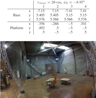
rmax= 28 cm, ψ0= −8.97◦ 1 2 3 4 Base x -7.15 7.15 -7.41 7.41 y 5.405 5.405 5.15 5.15 z 5.576 5.566 5.566 5.576 Platform x .356 -.266 -.5 .341 y .492 .5 -.5 -.5 z .5 -.5 -.5 .5
Fig. 11. The large cable-suspended parallel robot of the project CoGiRo [35]—Robot overall dimensions 15 m x 11 m x 6 m (L x l x h).
[2] S. Kawamura, W. Choe, S. Tanaka, and S. R. Pandian, “Development of an ultrahigh speed robot falcon using wire drive system,” in Proc. IEEE
Int. Conf. Robotics and Automation, Nagoya, Japan, 1995, pp. 215–220.
[3] M. Carricato and J.-P. Merlet, “Stability analysis of underconstrained cable-driven parallel robots,” IEEE Trans. on Robotics, vol. 29, no. 1, pp. 288–296, Feb. 2013.
[4] G. Rosati, D. Zanotto, and S. K. Agrawal, “On the design of adaptive cable-driven systems,” ASME Journal of Mechanisms and Robotics, vol. 3, May 2011.
[5] X. Zhou, C. P. Tang, and V. Krovi, “Analysis framework for cooperating mobile cable robots,” in Proc. IEEE Int. Conf. Robotics and Automation, Saint Paul, Minnesota, USA, 2012, pp. 3128–3133.
[6] P. Gallina and G. Rosati, “Manipulability of a planar wire driven haptic device,” Mech. and Mach. Theory, vol. 37, no. 2, pp. 215–228, Feb. 2002.
[7] R. L. Williams II, B. Snyder, J. S. Albus, and R. V. Bostelman, “Seven-dof cable-suspended robot with independent metrology,” in Proc. ASME
Design Engineering Technical Conf. and Computers and Information
in Engineering Conf., no. Paper DETC2004/MECH-57125 [CD-ROM],
Salt Lake City, UT, Sep. 2004.
[8] C. Ferraresi, M. Paoloni, S. Pastorelli, and F. Pescarmona, “A new 6-dof parallel robotic structure actuated by wires: The wiro-6.3,” J. of Robot.
Syst., vol. 21, no. 11, pp. 581–595, 2004.
[9] M. Hiller, S. Fang, S. Mielczarek, R. Verhoeven, and D. Franitza, “Design, analysis and realization of tendon-based parallel manipulators,”
Mech. and Mach. Theory, vol. 40, no. 4, pp. 429–445, Apr. 2005.
[10] R. L. Williams II, M. Xin, and P. Bosscher, “Contour-crafting-cartesian-cable robot system concepts: Workspace and stiffness comparisons,” in
Proc. ASME Int. Design Engineering Technical Conf. and Computers
and Information in Engineering Conf., no. Paper DETC2008-49478
[CD-ROM], Brooklyn, NY, Aug. 2008.
[11] M. M. Aref and H. D. Taghirad, “Geometrical workspace analysis of a cable-driven redundant parallel manipulator: KNTU CDRPM,” in Proc.
IEEE/RSJ Int. Conf. Intelligent Robots and Systems, Nice, France, 2008,
pp. 1958–1963.
[12] Y. Takeda and H. Funabashi, “Kinematic synthesis of spatial in-parallel wire-driven mechanism with six degrees of freedom with high force transmissibility,” in Proc. ASME Design Engineering Technical
Conf. and Computers and Information in Engineering Conf., no. Paper
DETC2000/MECH-14090, Baltimore, Maryland, USA, 2000. [13] S. Perreault and C. M. Gosselin, “Cable-driven parallel mechanisms:
Application to a locomotion interface,” ASME J. Mech. Des., vol. 130, no. 10, Oct. 2008.
[14] T. Bruckmann, L. Mikelsons, T. Brandt, M. Hiller, and D. Schramm,
“Design approaches for wire robots,” in Proc. ASME Int. Design
Engi-neering Technical Conf. and Computers and Information in EngiEngi-neering
Conf., no. Paper DETC2009-86720 [CD-ROM], San Diego, California,
USA, Sep. 2009.
[15] K. Azizian and P. Cardou, “The dimensional synthesis of planar parallel cable-driven mechanisms through convex relaxations,” ASME Journal of
Mechanisms and Robotics, vol. 4, no. 3, Aug. 2012.
[16] I. Ebert-Uphoff and P. A. Voglewede, “On the connections between cable-driven robots, parallel manipulators and grasping,” in Proc. IEEE
Int. Conf. Robotics and Automation, New Orleans, LA, 2004, pp. 4521–
4526.
[17] P. Lafourcade, M. Llibre, and C. Reboulet, “Design of a parallel wire-driven manipulator for wind tunnels,” in Proc. Workshop on
Funda-mental Issues and Future Research Directions for Parallel Mech. and
Manipulators, Quebec City, Canada, 2002, pp. 187–194.
[18] A. Pott, H. Mutherich, W. Kraus, V. Schmidt, P. Miermeister, and A. Verl, “IPAnema: A family of cable-driven parallel robots for industrial applications,” in Cable-Driven Parallel Robots, T. Bruckmann and A. Pott, Eds. Springer, 2013, pp. 119–134.
[19] S. Tadokoro, S. Nishioka, T. Kimura, M. Hattori, T. Takamori, and K. Maeda, “On fundamental design of wire configurations of wire-driven parallel manipulators with redundancy,” in Proceedings of the
1996 Japan/USA Symposium on Flexible Automation, Boston, MA, USA,
1996, pp. 151–158.
[20] H. Khakpour, L. Birglen, and S.-A. Tahan, “Synthesis of differentially driven planar cable parallel manipulators,” IEEE Trans. on Robotics, vol. 30, no. 3, pp. 619–630, Jun. 2014.
[21] J. Pusey, A. Fattah, S. Agrawal, and E. Messina, “Design and workspace analysis of a 6-6 cable-suspended parallel robot,” Mechanism and
Machine Theory, vol. 39, pp. 761–778, 2004.
[22] X. Tang and R. Yao, “Dimensional design of the six-cable driven parallel manipulator of FAST,” ASME J. Mech. Des., vol. 133, no. 11, Nov. 2011. [23] J.-D. Deschenes, P. Lambert, S. Perreault, N. Martel-Brisson, N. Zoso, A. Zaccarin, P. Hebert, S. Bouchard, and C. Gosselin, “A cable-driven parallel mechanism for capturing object appearance from multiple viewpoints,” in Sixth International Conference on 3-D Digital Imaging
and Modeling, Montreal, Canada, 2007.
[24] P. Bosscher, A. T. Riechel, and I. Ebert-Uphoff, “Wrench-feasible workspace generation for cable-driven robots,” IEEE Trans. on Robotics, vol. 22, no. 5, pp. 890–902, Oct. 2006.
[25] S. Bouchard, C. M. Gosselin, and B. Moore, “On the ability of a cable-driven robot to generate a prescribed set of wrenches,” ASME Journal
of Mechanisms and Robotics, vol. 2, no. 1, pp. 1–10, 2010.
[26] S. Abdelaziz, L. Esteveny, L. Barb´e, P. Renaud, B. Bayle, and M. de Mathelin, “Development of a mr-compatible cable-driven manipu-lator: design and technological issues,” in Proc. IEEE Int. Conf. Robotics
and Automation, Saint Paul, Minnesota, USA, 2012, pp. 1488–1494.
[27] A. Taghavi, S. Behzadipour, N. Khalilinasab, and H. Zohoor, “Workspace improvement of two-link cable-driven mechanisms with spring cable,” in Cable-Driven Parallel Robots, T. Bruckmann and A. Pott, Eds. Springer, 2013, pp. 201–213.
[28] R. G. Roberts, T. Graham, and T. Lippitt, “On the inverse kinematics, statics, and fault tolerance of cable-suspended robots,” J. of Robot. Syst., vol. 15, no. 10, pp. 581–597, 1998.
[29] G. M. Ziegler, Lectures on Polytopes. Springer-Verlag, Graduate Texts in Mathematics 152, 1994.
[30] M. Gouttefarde and S. Krut, “Characterization of parallel manipula-tor available wrench set facets,” in Advances in Robot Kinematics, J. Lenar˘ci˘c and M. M. Stani˘si´c, Eds. Springer, 2010, pp. 475–482. [31] V. Lumelsky, “On fast computations of distance between line segments,”
Information Processing Letters, vol. 21, no. 2, pp. 55–61, Aug. 1985.
[32] C. Ericson, Real-Time Collision Detection. Morgan Kaufmann Series in Interactive 3-D Technology, Jan. 2005.
[33] T. Papadopoulo and M. Lourakis, “Estimating the jacobian of the singular value decomposition: Theory and applications,” in European
Conference on Computer Vision, Dublin, Ireland, jun 2000, pp. 554–
570.
[34] M. Gouttefarde and C. M. Gosselin, “On the properties and the de-termination of the wrench-closure workspace of planar parallel cable-driven mechanisms,” in Proc. ASME Design Engineering Technical
Conf. and Computers and Information in Engineering Conf., no. Paper
DETC2004/MECH-57127 [CD-ROM], Salt Lake City, UT, Sep. 2004. [35] “Website of project CoGiRo,” http://www.lirmm.fr/cogiro/, 2013.