The Effect of Microstructure on the Fatigue and
Fracture Properties of Vintage Power Rotor Steels
by
Michael Philip Short
Submitted to the Department of Materials Science and Engineering
in partial fulfillment of the requirements for the degree of
Master of Science in Materials Science and Engineering
at the
MASSACHUSETTS INSTITUTE OF TECHNOLOGY
4
ntlrO &
@
Massachusetts Institute of Technology 2010. All rig
ARCHIVES
Signature redacted
Author ...
.
Department of Materials Science and Engineering
Certified by...
Signature redacted
July 26, 2010
Ronald G. Ballinger
Professor, Nuclear Science and Engineering and Materials Science and
Engineering
Certified by...
Certified by...
/I1Signature redacted
...
., UThesis Supervisor
Samuel M. Allen
Prof
r, Materials. Science and Engineering
i/TI ,- I
Signature
red acted
Thesis
Reader
Rui F. Vieira
Chief Mechanical Epgnr, Pjasrpa Science and Fusion Center
Signature redacted-
Thesis Reader
A ccepted by ...
...
Christine Ortiz
Chair, Departmental Committee on Graduate Students
'to 10
7OF TECHNOLOGY
SEP 2 4 2018
...
Q1RAR(E
77 Massachusetts Avenue Cambridge, MA 02139
http://Iibraries.mit.edu/ask
DISCLAIMER NOTICE
Due to the condition of the original material, there are unavoidable flaws in this reproduction. We have made every effort possible to provide you with the best copy available.
Thank you.
The images contained in this document are of the best quality available.
The Effect of Microstructure on the Fatigue and Fracture
Properties of Vintage Power Rotor Steels
by
Michael Philip Short
Submitted to the Department of Materials Science and Engineering on July 26, 2010, in partial fulfillment of the
requirements for the degree of
Master of Science in Materials Science and Engineering
Abstract
MIT's Alcator C-Mod fusion experiment makes use of a large spinning mass coupled to a generator as its power source. A significant fraction of this mass consists of a 225 MVA generator rotor that was retired from power plant service. As part of normal maintenance, a periodic inspection by non-destructive evaluation (NDE) is performed to determine if flaws have developed, or progressed from pre-existing conditions, that exceed safe limits for operation. In 2008, after over fifty years of service at a power plant and at Alcator, the organization that performed the most recent inspection recommended that the rotor should not be returned to service. The basis for the rejection of the rotor was not clear, since the inspection did not reveal any change in the distribution of indications by NDE. Moreover, an independent fitness-for-service evaluation concluded that the rotor was safe to operate. However, the rejection was considered a serious enough event to warrant a more complete analysis of the condition of the rotor prior to continued operation. The cost of replacing or repairing the rotor was prohibitively expensive in terms of capital cost and experimental time lost.
This prompted an exhaustive investigation into the current state of the main rotor in order to more accurately determine whether or not it was still fit for service. After an extensive test program which included ultrasonic (UT) scans, tensile tests, fracture toughness (FT) tests, crack growth (CG) tests and microstructural analysis, it was determined that the physical and mechanical properties of the rotor were more than adequate, and that neither its properties nor its microstructure had changed appreciably since it was first forged. The rotor was therefore shown to still be fit for operation.
While the UT, tensile, FT and CG tests documented the mechanical properties of the rotor, analysis of the microstructure and the crack path during fatigue and frac-ture testing further documented and verified the stability of the material with respect to cracking resistance. Detailed microstructural characterization determined the re-lationship between the indications as identified by NDE (assumed to be cracks by the fitness-for-service analysis) and their actual morphologies. These were ultimately shown to be benign microstructural features that did not degrade the operating
ca-pability or cracking resistance of the rotor.
This thesis details the results of this microstructural analysis by optical and elec-tron microscopy, as well as the conclusions based on said analysis. In addition, an explanation as to how features observed in the data arose gives more insight into the viability of similar rotors, the serviceability of which has come into question due to age alone. The results of the analysis show that the rotor properties are more than ad-equate for continued operation. The results of the microstructural and fractographic analysis are consistent with the measured mechanical properties and demonstrate that further operation is justified.
Thesis Supervisor: Ronald G. Ballinger
Title: Professor, Nuclear Science and Engineering and Materials Science and Engi-neering
Thesis Reader: Samuel M. Allen
Title: Professor, Materials Science and Engineering Thesis Reader: Rui F. Vieira
Acknowledgments
First and foremost, I wish to thank Professor Ron Ballinger for being my advisor throughout my undergraduate and graduate studies for nearly a decade. He has provided a tremendous amount of insight, support, expertise and camraderie over the past years, and for that I am eternally grateful.
Special thanks also go to the entire Alcator team, who showed me how a group of already busy people can knuckle down and effectively accomplish a monumental task.
I especially want to thank Rui Vieira, for being my thesis reader and my primary
contact point throughout the project, and Bill Beck, Bob Granetz and Jim Irby for providing the insight, explanations and expertise I needed to make sense of all the data I collected.
Thanks are also due to Professor Sam Allen, who I've known since I arrived at MIT as an undergraduate nine years ago. When I took a blacksmithing and metallurgy class co-taught by him, I had no idea that it would lead me to a career studying metals. I originally wanted to be an electrical engineer, but blacksmithing and other metalwork sparked my interest far more.
Thanks also go to Toby Bashaw, and to JD Smith of MassArt, for teaching me most of what I know about working hands-on with metals. The intuition I gained
by working on real projects with them helped me to intuitively understand complex
microstructural processes by seeing and feeling their effects on larger pieces of metal. Books are one thing, but their knowledge combined with real experience is the most effective teaching tool there is.
The Uhlig corrosion lab provided me with an excellent working environment, full of interesting and dynamic people who aren't afraid to be politically incorrect in order to get the job done and have a good time. I specifically want to thank Julian Benz, Mike Dunlevy, Jon Gibbs, Joe Hubley, and Tim Lucas for being great colleagues, sounding boards for ideas, and friends.
I wish to say thank you to my family for their undying support throughout all
a serious problem to solve or just wanted someone to talk to.
Finally, I want to say thank you to my wife, Marina. Marrying you has shown me that there are some things in life where you need to plunge in head first, hold nothing back, and give it your all. I used to be worried about being stuck in a marriage, never wanting to be tied down to anything. Being with you showed me that you can't be stuck in something you enjoy so much, that I feel priviliged to be part of our relationship. I love you, sweetie.
Contents
1 Introduction 23
1.1 Origins of the Project . . . . 23
1.2 Description of Alcator and Its Main Rotor . . . . 24
1.3 Basis of the Decision Not to Operate the Rotor . . . . 25
1.4 Impact of the Decision Not to Operate the Rotor . . . . 26
1.5 Research Objectives. . . . . 27
1.6 Outline and Key Points. . . . . 28
2 Background 31 2.1 Manufacture and History of the Alcator Rotor . . . . 31
2.2 Chemistry of the Rotor and its Implications . . . . 31
2.3 Common Defects in Vintage Low Alloy Steel Forgings and Their Im-plications . . . . 33
2.4 Possible Methods of Crack Growth in Large Rotors . . . . 36
2.5 Case Study - Rotor #1 Failure at the Pittsburgh Station of the Pacific Gas and Electric Company . . . . 39
3 Experimental Work 41 3.1 Sample Extraction and Types . . . . 41
3.1.1 Intact Rotor Ring . . . . 42
3.1.2 M achined Chips . . . . 43
3.1.3 Rotor Ring Slices . . . . 45
3.1.5 Fracture Toughness Specimens. 4
3.1.6 Crack Growth Specimens . . . .
3.2 Sample Analysis Techniques . . . .
3.2.1 M ounting . . . .
3.2.2 Polishing . . . .
3.2.3 Etching . . . .
3.2.4 Optical Microscopy . . . . 3.2.5 Scanning Electron Microscopy (SEM) . . . .
3.2.6 Energy Dispersive X-ray (EDX) Spectroscopy
3.3 Sample Preparation and Analysis . . . .
3.3.1 Intact Rotor Ring . . . .
3.3.2 Machining Chips . . . .
3.3.3 Rotor Ring Slices . . . .
3.3.4 Tensile Specimens . . . .
3.3.5 Fracture Toughness Specimens . . . .
3.3.6 Crack Growth Specimens . . . .
3.4 Associated Mechanical Testing . . . . 3.4.1 Tensile Testing . . . . 3.4.2 Fracture Toughness Testing . . . . 3.4.3 Crack Growth Testing . . . .
4 Results
4.1 Intact Rotor Ring . . . . 4.1.1 Base Microstructure . . . .
4.1.2 Voids and Defects . . . . 4.2 Machining Chips . . . . 4.3 Rotor Ring Slices . . . . 4.3.1 Rotor Ring Slice #2 . . . .
4.3.1.1 Unetched SEM Analysis . . . . 4.3.1.2 Etched SEM Analysis . . . ..
. . . . 48 . . . . 48 . . . . 48 . . . . 49 . . . . 49 . . . . 50 . . . . 50 . . . . 51 . . . . 53 . . . . 53 . . . . 53 . . . . 53 . . . . 54 . . . . 54 . . . . 55 . . . . 55 . . . . 55 . . . . 55 57 59 59 59 61 62 63 64 64 68 47
4.3.2 Rotor Ring Slice #4 . . . .
4.3.2.1 Unetched SEM Analysis . . . . 4.3.2.2 Etched SEM Analysis . . . . 4.4 Tensile Specimens . . . . 4.4.1 Tensile Specimen #1 . . . .
4.4.1.1 Optical Microscopy - Unetched . . . 4.4.1.2 Optical Microscopy - Heavy Etch . .
4.4.1.3 SEM Analysis . . . .
4.4.2 Tensile Specimen #2 . . . .
4.4.2.1 Optical Microscopy - Unetched . . .
4.4.2.2 Optical Microscopy - Heavy Etch . .
4.4.2.3 SEM Analysis . . . .
4.4.3 Tensile Specimen #4 . . . .
4.4.3.1 Optical Microscopy - Unetched . . . 4.4.3.2 Optical Microscopy - Heavily Etched 4.4.3.3 Optical Microscopy - Lightly Etched 4.4.3.4 SEM Analysis . . . .
4.4.4 Tensile Specimen #5 . . . .
4.4.4.1 Optical Microscopy - Unetched . . . 4.4.4.2 Optical Microscopy - Heavily Etched 4.4.4.3 Optical Microscopy - Lightly Etched 4.4.4.4 SEM Analysis . . . .
4.5 Fracture Toughness Specimens . . . . 4.5.1 Stereo Microscope Analysis . . . .
4.5.2 SEM Analysis . . . .
4.6 Crack Growth Specimens . . . . 4.6.1 Crack Growth Specimen #1 . . . .
4.6.1.1 Optical Microscope - Lightly Etched 4.6.1.2 SEM Analysis . . . .
4.7 Associated Mechanical Testing Data . . . .
. . . . 70 . . . . 70 . . . . 72 . . . . 73 . . . . 78 . . . . 78 . . . . 78 . . . . 78 . . . . 82 . . . . 82 . . . . 84 . . . . 84 . . . . 84 . . . . 88 . . . . 88 . . . . 88 . . . . 92 . . . . 93 . . . . 93 . . . . 93 . . . . 96 . . . . 96 . . . . 96 . . . . 96 . . . . 99 . . . . 100 . . . . 100 . . . . 100 . . . . 104 . . . . 104
4.7.1 Tensile Tests . . . .
4.7.2 Fracture Toughness Tests . . .
4.7.3 Crack Growth Tests . . . .
4.8 Rotor Inspection Data . . . .
5 Discussion
5.1 Overview. . . . .
5.2 Initial Tests . . . .
5.3 Types of Defects Observed . . . .
5.3.1 MnS Precipitates . . . .
5.3.2 Voids . . . .
5.4 Effects of Microstructural Anomalies on
5.4.1 MnS Precipitates . . . .
5.4.2 Voids . . . . 5.5 Comparison of Past and Present Data.
Mechanical
6 Conclusion
6.1 Validity of the 2008 Recommendation . . . .
6.2 Recommendations for the Future . . . .
Bibliography I
A Drawing of Alcator's Main Rotor 1
B Original Manufacturer Forging Specification 1
C Analysis of the Failure of Rotor #1 at the Pittsburgh Station of the
Pacific Gas and Electric Company 1
D Rotor NDE Inspection Reports I
D.1 Forging Report, 1978 . . . . D.2 Rotor Evaluation, 1982 . . . . D.3 NDT Inspection Report, 1985 . . . . 104 107 107 108 111 111 112 114 114 115 118 118 120 122 Properties 27 127 128 29 35 37 41 45 145 148 150
D.4 Rotor Bore Surface Examinations, 1989 . . . . 153
D.5 Rotor Inspection, 1996 . . . . 156
D.6 Generator Rotor Inspection Report, 2003 . . . . 159
E Recommendation for Removal of Rotor from Service, 2008 161
E.1 Letter from NDE Inspector to MIT, 2008 . . . . 161
E.2 Report on Rotor NDE Inspection, 2008 . . . . 164
List of Figures
2-1 Fe-C binary phase diagram [11 . . . . 34
3-1 Three dimensional indication map as generated by UT inspection. The smallest detectable indication size was 200 pm. The axial UT map shows that the groupings of indications are not continuous in the radial direction, making them far less potentially damaging to the rotor. . . 43
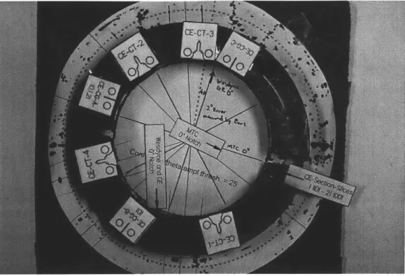
3-2 Rotor ring provided by Alcator for preliminary analysis. Locations where samples were taken are marked with paper printouts of their shapes at their original locations. . . . . 44
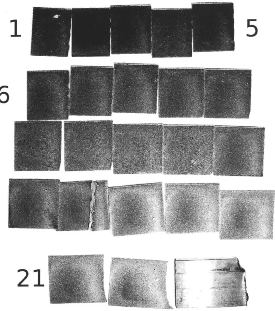
3-3 All rotor ring slices removed from the rotor, with large voids visible to
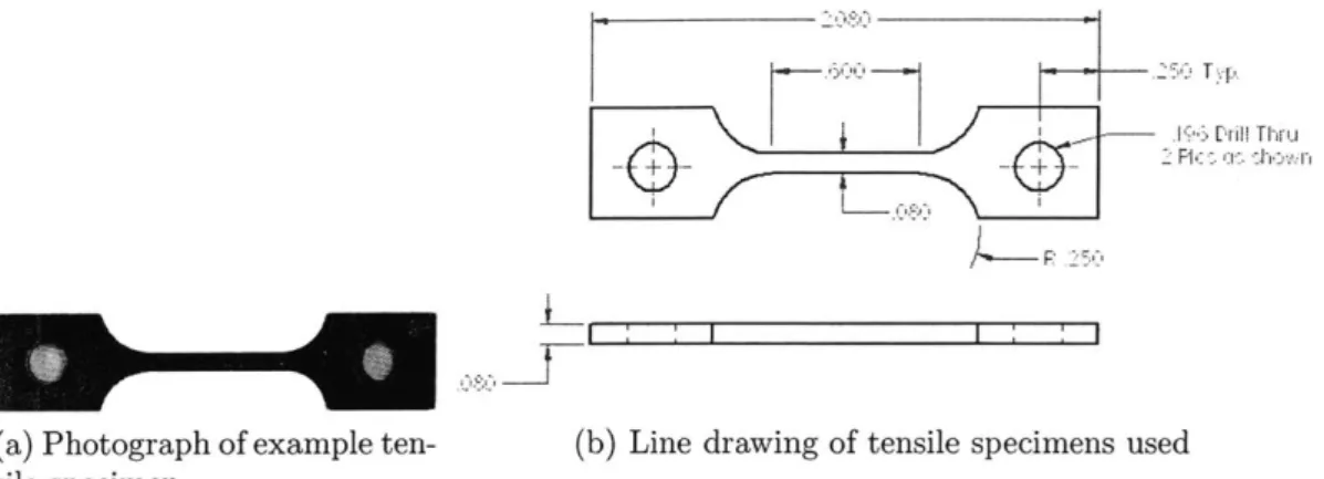
the naked eye. Slice #17 was fractured by hand along a group of voids in order to look inside them. . . . . 46 3-4 Example tensile specimen from the rotor ring along with dimensional
diagram. Dimensions shown are in inches. . . . . 47
3-5 Example fracture toughness specimen from the rotor ring along with
dimensional diagram. Dimensions are given in inches. . . . . 47
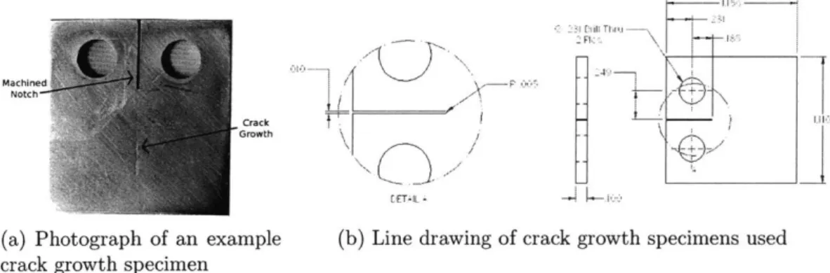
3-6 Example crack growth specimen from the rotor ring along with
dimen-sional diagram. Dimensions are given in inches. . . . . 48
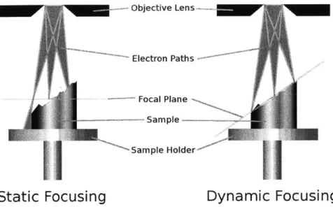
3-7 Diagram of static versus dynamic focusing in an SEM. Dynamic
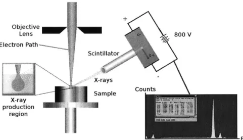
focus-ing rotates the focal plane by changfocus-ing the focal distance of the beam as the SEM rasters the beam in the y-direction. . . . . 51 3-8 Diagram of how EDX works. X-rays generated by electron transitions
3-9 Sectioning procedure for tensile samples. The two rectangular sections
were mounted for cross section and transverse section analysis, and the small piece provided both the actual fracture surface and a view of deformation mechanics on the side. . . . . 54
3-10 Example stress vs. strain curve found in this study. The reported yield
stress is given by the purple line, where the grey line (0.2% strain) intersects the experimental data. . . . . 56
4-1 Optical micrographs of the intact rotor ring . . . . 60
4-2 Micrograph of interconnected voids in the rotor ring, 50x . . . . 61
4-3 A partially closed void observed on the intact rotor ring, 100x . . . . 62 4-4 Wide area EDX spectrum of machining chips . . . . 62
4-5 Example photographs of rotor ring slices before and after etching. Black areas are typically voids, while browner areas are overetched due to a galvanic couple between precipitates and the surrounding mi-crostructure.. . ... ... .. . . .. ... .. .. . . ... . . . 63
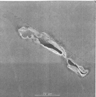
4-6 SEM and EDX analysis of a large void on slice #2. EDX analysis shows an internal oxidation zone corresponding to the darker areas lining the void and at the tip of the void. . . . . 65
4-7 SEM and EDX analysis of a void on slice #2 surrounded by dark material. EDX analysis again shows an internal oxidation zone corre-sponding to the darker areas lining the void, along with correcorre-sponding Fe depletion. . . . . 66
4-8 SEI images of a partially closed void found in slice #2 . . . . 67
4-9 SEM and EDX analysis of a completely closed microstructural anomaly on slice #2. EDX analysis again shows an internal oxidation zone corre-sponding to the darker areas lining the void, along with correcorre-sponding Fe depletion. . . . . 69
4-10 SEI of slice #2 after etching in 5% nital, 20 x. This micrograph shows the density of defects present in the sample, highlighted by galvanic corrosion immediately surrounding each defect. . . . . 70
4-11 SEM image of slice #2 after etching, showing MnS precipitates at the center of each dark region of overetching, 40x. Black spots are either voids or charged particles of dust on the sample. . . . . 71
4-12 SEM image of slice #2 after etching showing the base microstructure, 300x. Lighter regions have been etched more heavily, and are likely bainite based on the higher number of carbides present in this phase. 72
4-13 SEM image of two networked voids on slice #2, 20 x. The underetched areas are indicative of an opening or other microstructural anomalies linking the two voids. . . . . 73
4-14 SEM images of the closed region connecting the first two voids explored on slice #2, 200x. The underetched region revealed a closed portion of the void connecting the two previously analyzed voids. . . . . 74 4-15 SEM analysis of a void on slice #4 surrounded by dark material. Closer
inspection of the dark material reveals small microcracks throughout that do not extend beyond the dark boundary... 74 4-16 SEM and EDX analysis of a region of a void on slice #4 surrounded by
dark material, 150 x. EDX analysis again shows an internal oxidation zone corresponding to the darker areas lining the void, along with corresponding Fe depletion. . . . . 75
4-17 SEM and EDX analysis of a region of a void on slice #4 surrounded by dark material, 230x. EDX analysis again shows an internal oxidation zone along with an Fe depletion zone that line up precisely with the dark region in the SEM image . . . . 76
4-18 Comparison of the degree of underetching around MnS precipitates and around voids on slice #4 . . . . 77
4-19 Unetched optical micrographs of tensile sample #1 showing distribu-tion of MnS precipitates. These are the purplish-gray spherical features present in all micrographs. Straight lines are scratches from polishing and should be ignored. . . . . 79
4-20 Heavily etched optical micrographs of tensile sample #1 showing mi-crostructure, voids and MnS precipitates. No preferred orientation exists for any features in the sample. Regions of ferrite were found to surround some anomalies, especially voids. . . . . 80
4-21 SEI of entire fracture surface of tensile sample 1, 150x . . . . 81
4-22 SEM images of the side of tensile sample #1, showing slip systems activated at a 45 0 angle to the axis of tension . . . . 82
4-23 Unetched optical micrographs of tensile sample #2 showing distribu-tion of MnS precipitates, as well as one large void containing a number
of M nS precipitates . . . . 83
4-24 Etched optical micrographs of tensile sample #2, clearly showing lighter areas of ferrite surrounding any microstructural anomalies that contain em pty space . . . . 85
4-25 SEI of the entire fracture surface of tensile sample 2, 150x . . . . 86
4-26 EDX elemental map of defects on tensile sample #2, showing that MnS precipitates and not carbides are responsible for the cup-and-cone fracture surfaces observed on this sample . . . . 87
4-27 SEM images of the side of tensile sample #2, showing slip systems activated at a 450 angle to the axis of tension. . . . . 88
4-28 Unetched optical micrographs of tensile sample #4 showing a high den-sity of MnS precipitates with no preferred orientation. Large rounded voids are visible in all micrographs. . . . . 89
4-29 Heavily etched optical micrographs of tensile sample #4 showing mi-crostructure, voids and MnS precipitates. No preferred orientation exists for any features in the sample. Rainbow regions are areas of galvanic corrosion at the interface between the steel and MnS. .... 90
4-30 Lightly etched optical micrographs of tensile sample #4 clearly high-lighting areas of ferrite surrounding voids . . . . 91
4-31 SEM images of typical microstructural features observed on the frac-ture surface of tensile sample #4. This sample exhibited both regions of ductile and brittle fracture. . . . . 92
4-32 SEM images of the side of tensile sample #4 showing far fewer ductile features than in previously analyzed samples . . . . 93
4-33 Unetched optical micrographs of tensile sample #5 showing a high den-sity of MnS precipitates with no preferred orientation. Large anoma-lies, both voids and MnS precipitates, are visible in all micrographs. . 94 4-34 Heavily etched optical micrographs of tensile sample #5 showing
mi-crostructure, voids and MnS precipitates. Almost half the surface has been affected by galvanic corrosion, indicating a very high density of defects. . . . . 95
4-35 Lightly etched optical micrographs of tensile sample #5 clearly
high-lighting areas of ferrite surrounding voids and other anomalies . . . . 97 4-36 Ductile and brittle fracture features found side-by-side on the fracture
surface of tensile sample #5 . . . . 98
4-37 Ductile and brittle features observed on the side of tensile sample #5 99
4-38 Stereo microscope images of fracture toughness sample #2. Note the large number of shiny spots on both images indicating cleavage planes. 100 4-39 Typical SEM images of the fracture surface of fracture toughness
spec-imen #2, showing a uniformly distributed mix of ductile and brittle features . . . . 101
4-40 SEM images of the shelf-like feature observed on the crack surface of sample FT-2. These images show that the feature contained brittle fast-fracture paths, and that the material fractured along these planes as well as perpendicular to the crack face. . . . . 102
4-41 Typical optical micrographs of anomalies found on crack growth sam-ple #1. Large voids and MnS precipitates were found, with ferrite encircling some voids. Any long thin lines are scratches and should be ignored . . . . 103
4-42 Typical SEM images of crack growth specimen #1. Both cleavage planes and fatigue striations were observed on the crack surface, with more ductile features than brittle ones. . . . . 105
4-43 SEM image and EDX maps of long MnS precipitates found on the crack face of sample CG-1 . . . . 106
4-44 LLD curve for the fracture toughness test of sample FT-2 . . . . 107
4-45 - vs. AK data for crack growth testing of sample CG-1 . . . . 108
dN
List of Tables
2.1 Average reported chemistry for the rotor . . . . 31 3.2 Sample matrix for samples analyzed in this thesis . . . . 42 4.1 Comparison of composition reported in forging specification with that
measured by EDX. "Trace" means a small amount was detected, but it was too small to quantify. Uncertainties were calculated by software. 63 4.2 Summary of tensile test data for specimens microstructurally examined
in this study . . . . 105
4.3 Summary of NDE inspection reports carried out on the rotor. The 'Favorable' column is a determination as to whether or not the new data merit continued operation of the rotor. Starting in 1992, max-imum sizes of observed indications were given as groups rather than individual particles, as the test reporting method had changed. . .. . 109 5.1 Comparison of expected tensile properties for ASTM-469 Grade 3 steel
with those observed in both defect-poor and defect-rich sections of the rotor ring . . . . 119 5.2 Comparison of expected fracture toughness properties for ASTM-469
List of Abbreviations and Symbols
Used in This Study
Abbreviations
Amer. Society for Testing & Materials Crack Growth
Electrical Discharge Machining Energy Dispersive X-ray (analysis) Fracture Toughness
General Electric Company Hardness Vickers
Linear Displacement
Load vs. Linear Displacement (curve) Magneto HydroDynamics
Massachusetts Institute of Technology Non-Destructive Evaluation
Nil Ductility Temperature Radio Frequency
Secondary Electron Image Scanning Electron Microscopy Stress Intensity Factor
Tensile Sample
Time & Temperature Transformation Ultrasonic Testing a Ac d E g JIC K1 Kic P Pz r W Ot p o-v LU Symbols Crack Length
Cross Sectional Area Diameter Young's Modulus Gravtational Acceleration Critical J-Integral Fracture Toughness Critical K1 Pressure Perimeter Radius Crack Width Engineering Strain Tilt Angle Density Stress Poisson's Ratio Rotational Speed ASTM CG EDM EDX FT GE HV LD LLD MHD MIT NDE NDT RF SEI SEM SIF TS TTT UT
Chapter 1
Introduction
1.1
Origins of the Project
In 2008, after over fifty years of time in service, the results of a periodic non-destructive evaluation (NDE) of the rotor resulted in a recommendation that the main rotor for MIT's Alcator fusion reactor should not be returned to service [3]. This is in spite of the fact that this inspection and all previous NDE studies per-formed every five years had not shown any appreciable changes in "indication" sizes or distributions, assumed to be flaws for structural analysis purposes. However, the decision was made not to continue operation of the main rotor until further analysis could be performed to more accurately characterize its condition. This would have essentially put the Alcator experiment, a key program and a national facility in the MIT Plasma Science and Fusion Center, out of commission, due to the extremely high cost and time delay in procuring and replacing a suitable rotor. MIT therefore decided to assemble a team of researchers to perform a more detailed characterization of the rotor.
The researchers felt that much of the concern for further operation of the rotor was related to an increase in conservatism due to the rotor's age, despite essentially constant analysis results over the past fifty years. The rotor was produced in the early 1950s when casting and forging processes were much less mature. This resulted in a higher variability in mechanical properties. Additionally, NDE techniques, when
applied to this vintage of rotor forgings, often yield results that indicate defect (hence-forth referred to as "indication") distributions that appear to be unfavorable. These two sources of uncertainty, coupled with a lack of actual mechanical property data for this rotor, required a very conservative fitness-for-service analysis. However, the fitness-for-service process allows for the use of physical and mechanical properties data specific to the rotor if they are available. Given the urgency of the situation, it was essential that such data be obtained and a more accurate fitness-for-service analysis performed. Thus, an extensive program was conducted to obtain the needed data as well as to characterize the microstructure of the rotor. The results of the detailed microstructural and fractographic analysis are presented in this thesis.
1.2
Description of Alcator and Its Main Rotor
MIT's Alcator fusion experiment is a prototypical TOKAMAK style fusion confine-ment where scientists study the physics, magneto-hydrodynamic (MHD) characteris-tics and associated issues involved in generating a plasma suitable for power produc-tion. The Alcator approach uses a very high magnetic field and a compact geometry to electro-magnetically confine the plasma away from the walls of the device while heating it to temperatures of tens of millions of degrees. At these pressures and temperatures, fusion reactions become possible.
The magnetic confinement system relies on extremely high strength toroidal and poloidal field electromagnets to confine the plasma into a torus inside the device. In addition, radio frequency (RF) heaters pump up to 4 MW of power into the plasma to increase its temperature. The combination of toroidal fields (circumferentially along the torus) and poloidal field lines (wrapping around the torus) serves to create a stable confinement system for the plasma [4]. In order for the plasma to move in a stable path, i (the change magnetic field strength) must remain constant and positive, where B is the strength of the magnetic field supplied by the electromagnets to confine the plasma. The strength of the poloidal field must therefore be continuously increased as the plasma burns. After a certain amount of time the electromagnets,
normally kept at the temperature of liquid nitrogen, heat up enough that they must be shut off, restricting the plasma burn time. The mission of the Alcator experiment is to increase this burn time, with the ultimate goal of developing a fusion reactor that produces more energy than it consumes.
The combination of high power electromagnets and multi-megawatt RF heaters requires an immense amount of power, too large to be supplied by the local power grid and maintain grid stability. Therefore a rotational kinetic energy system was devised, consisting of a 70 ton flywheel spinning in a vacuum attached to an alternator via a large steel rotor. This flywheel is gradually spun up to 1,700 RPM using a minimal amount of grid power. When a 'shot' (plasma discharge) is made, this flywheel is electrically connected to the alternator via a stator on the rotor, and is inductively slowed down to 1,620 RPM. The change in kinetic rotational energy supplies the electromagnets and the RF heaters with the power necessary to heat and confine the plasma.
1.3
Basis of the Decision Not to Operate the Rotor
Quickly changing rotational speed from 1,700 RPM to 1,620 RPM puts significant stress on a rotor/flywheel assembly that weighs over 200 tons. There is a valid cause for concern that flaws present as a result of manufacturing could detrimentally affect the microstructure and structural integrity of the rotor over time, possibly leading to total failure. Complete failure of a 200 ton assembly spinning at 1,700 RPM is not an option. A complete NDE of the rotor by ultrasonic testing (UT) is performed every five years in order to track and document any observed indications, along with their sizes and orientations. The NDE process, while capable of detecting some differences in material morphology, requires that additional information be available before an indication can be considered an actual flaw. Sources of this information can include past experience, calibration data or direct data from testing the part. A conservative assumption must often be made with older rotors, assuming that the indications are indeed flaws or cracks that can be expected to grow during operation.
Following the most recent scheduled NDE of the rotor in 2008, MIT decided not to proceed with continued operation until a more extensive analysis of the rotor was made [3]. The firm performing the inspection had recommended against continued operation of the rotor. The reason cited was its "structural integrity" based on the results of the NDE. However, no appreciable changes existed between the most recent and inspections [5, 6, 7, 8, 9, 10]. The decision not to certify continued operation of
the rotor was more likely a reflection of increased conservatism becoming prevalent in the industry to avoid potential liability, as no scientific basis for the decision was cited. This brought into question the reason not to continue operation the rotor.
1.4
Impact of the Decision Not to Operate the
Ro-tor
A decision not to operate the rotor would have caused one of two scenarios to take
place:
" The main rotor would have to be replaced, but with a very long (2 - 5 years)
lead time for replacement part procurement.
* The rotor would have to be bored out to physically remove the bulk of the indications, with the attendant risk that this would not solve the problem. The first scenario was prohibitively expensive, and would result in at least a three year time where the facility would be unavailable. The current rotor was donated to MIT by the Con-Edison Electric Company. A new rotor was estimated to cost over $12 million in materials and labor. It would have taken two years just to secure a manufacturing time due to limited world capability to create such large parts, and extensive custom machining would have been required. The second scenario, while not as expensive ($1.5 million), would require a large amount of time to carefully bore out the rotor to remove most of the flaws. There was also no guarantee that boring the rotor would not have exposed more flaws at the new inner diameter, where
they would be most damaging. Most of the microstructural anomalies in the rotor are found near the center; reasons for this will be explained in the next chapter. Because the facility's funding from the U.S. government is partially contingent on the production of new data, the time required to bore the rotor would have put the facility's future in danger.
1.5
Research Objectives
The main goal of this research was to participate in the evaluation of the structural integrity of Alcator's main rotor by augmenting evaluation of mechanical properties with microstructural analysis. Sample selection, sectioning, etching and subsequent analysis by optical microscopy and scanning electron microscopy (SEM) coupled with elemental dispersive x-ray (EDX) analysis provided a window into how the rotor was made, what changes may have occurred during service, and what changes, if any, are expected to take place over its lifetime. This data combined with UT scans, tensile, fracture toughness and crack growth tests, and reports generated by other researchers gave a complete record of what had happened to the rotor over time.
Reports from the first forging on the rotor, a history of UT scans, microstructural analysis and testing of physical properties all point to good structural integrity for the rotor. The data developed in this thesis added additional confirmation of the rotor's fitness-for-service. This claim will be supported with the following types of evidence:
1. Knowledge of how microstructural anomalies form both during forging and
cast-ing of such a rotor, specifically uscast-ing methods from fifty years ago, will be compared with anomaly sizes and locations observed in the rotor today.
2. Etched and unetched optical micrographs of the base microstructure along with observed anomalies and precipitates will show whether the material has been stressed preferentially in one direction, whether microstructural changes have taken place, and whether any regions of differing microstructure are present in
the material. These along with the morphologies of the anomalies will point to when they were created.
3. SEM and EDX analysis of the microstructural anomalies in particular will show
high resolution images of regions with the highest stress concentration along with any elemental segregation or movement. These data will show that changes have not taken place in the rotor during service, and will further suggest that normal operating conditions will not change the integrity of the rotor.
4. SEM and EDX of the fracture surfaces of tensile, fracture toughness and crack growth specimens will show that the material is sufficiently ductile, meaning that it is not expected to undergo cyclic fatigue or sudden brittle fracture. This data will be put into context using models of expected stress distributions and flaw distributions in the rotor.
5. Tensile data and crack growth data from good poor) and bad
(defect-rich) regions in the rotor will be combined with SEM and optical data above to estimate the maximum allowable stresses in this material, and then compared with the highest stresses expected during service.
1.6
Outline and Key Points
Chapter 2 presents a documented history of Alcator's main rotor, along with rel-evant literature from similarly fabricated rotors. The quality of chemistry control and casting & forging techniques will be discussed with relevance to how they af-fect microstructural anomalies and their distributions throughout the rotor. The microstructure of steels used for power rotors in the 1950s will be explained in terms of chemistry, heat treatment, processing and irregularities present. Tensile properties and crack growth properties will be discussed. The role of voids and inclusions in determining properties, such as functioning as stress concentrators, will be reviewed. Chapter 3 presents the experimental work carried out by the author and others to determine the quality of the rotor material. Sample extraction and selection
method-ology, sample preparation and analysis techniques will be summarized. Descriptions of sample preparation and analysis techniques will be given with the aim of explaining how these techniques are suited to the goals of this thesis.
Chapter 4 summarizes the results of each method of analysis. Optical micrographs without etching show the sizes and locations of significant microstructural anomalies with high contrast, while etched optical micrographs show the base microstructure and any regions of microstructural deviation. SEM data of unetched cross sections of the rotor show more details on the edges of potential flaws, and show that no brittle crack growth or fatigue has taken place during operation. EDX maps show regions of differing elemental concentration, and EDX spot and line scans determine the chemistry of phases present as well as precipitates found in the material. SEM images of the fracture surfaces of tensile specimens and crack growth specimens show how the test material fractured, and the percent ductility in each region.
Chapter 5 discusses the meaning and implications of each set of data. The shapes
and sizes of potential flaws and precipitates are shown to be consistent with the quality of metallurgy in the 1950s, when this rotor was made. Etching revealed regions of lower carbon concentration around many anomalies, showing that they were formed during fabrication, and that they are more ductile than the surrounding material.
SEM micrographs show that no potential flaws have grown over the lifetime of the
rotor, and therefore that the operating stresses were well below those required for crack growth. EDX maps confirm that regions of decarburization exist around many voids, supporting the claim from the optical micrographs. SEM examination of the fracture surfaces of tensile and crack growth specimens show expected behavior for the steel given the distributions of anomalies, eliminating the possibility that sulfur has embrittled grain boundaries, which would have lead to brittle fracture.
Finally, chapter 6 presents an overall conclusion based on the literature, research and analysis conducted in this thesis and by other scientists at MIT. The decision not to operate the rotor based on a lack of structural integrity is shown to be unnecessary, as previous decisions to continue operation were based on data nearly identical to those collected during the most recent NDE and in this thesis.
Chapter 2
Background
2.1
Manufacture and History of the Alcator Rotor
The rotor was constructed in 1951 from two separate forgings with similar properties and chemistries. Metal chemistries and physical properties were determined at the time of forging and documented in the forging specification, shown in Appendix B. After the initial casting and forging, the rotor was used by Con-Edison to generate electricity in Brooklyn. The rotor was then donated to MIT in 1977, where it began service on the Alcator toroidal fusion reactor. Since the late 1970s, Alcator has utilized the large rotational kinetic energy stored in the rotor to provide pulsed high power to Alcator's magnets and other subsystems. A 70 ton flywheel was added in
1994 to provide more rotational energy.
2.2
Chemistry of the Rotor and its Implications
The average chemistry of the two forgings as reported by the manufacturer is given below in Table 2.1. The chemistries and physical properties of the two forgings are
Element Fe C Mn P S Si Ni Cr Mo V
Wt. % Bal. 0.245 0.588 0.030 0.025 0.218 2.548 0.098 0.498 0.070 Table 2.1: Average reported chemistry for the rotor
very similar, and both underwent similar processing steps.
The effects of individual elements on properties and microstructure are summa-rized here. Carbon is added to make the steel hardenable. 0.25 wt. % carbon is enough to produce either pearlite or bainite in a properly hardened steel. Molybdenum is often added for strength, and to promote the formation of bainite by changing the Time-Temperature Transformation (TTT) curve [11]. As little as 0.35 wt. % Mo has been shown to produce a completely ferritic-bainitic steel [11]. Silicon is present in order to 'kill' the steel. During casting silicon binds to free oxygen, and the result-ing metal oxide is removed as slag. Phosphorus and sulfur are unwanted elements whose concentrations should usually be as low as possible. Sulfur in particular col-lects on the grain boundaries during casting and forging, forming Fe-S compounds that severely weaken the steel [12, 13]. Manganese is added to mitigate this effect; about twenty times the sulfur concentration has been shown to completely counteract the weakening effect of sulfur on the microstructure by forming well dispersed, round MnS precipitates [14]. These have a very small effect on the microstructure, especially when compared with Fe-S compounds on the grain boundaries. Nickel is added as an austenite stabilizer, and vanadium is present in small amounts for added strength.
Based on the specific chemistry of this particular rotor, it is expected that a heat treatment of annealing followed by fairly rapid quenching in water or oil would have produced a ferritic/bainitic microstructure with a fine grain structure, on the order of tens of microns in size. The relatively high carbon content coupled with the sufficiently high Mo content (which stabilizes bainite) and the sufficiently low Si content (which destabilizes bainite) produces a more bainitic microstructure. This is desirable from the standpoint of operating stresses, as a bainitic microstructure strikes a good balance between toughness and hardness, which will be good at resisting deformation due to high centripetal forces as a result of spinning the rotor.
The chemistries of the two forgings were likely determined from the outer regions of the rotor, due to the relatively low amounts of impurities present in the forging from those that would be expected. It has also been shown that as a large casting
solidifying faster than the inside [15]. It was therefore expected that the chemistry of the inside of the rotor would be significantly worse than that of the outside.
2.3
Common Defects in Vintage Low Alloy Steel
Forgings and Their Implications
The presence of slag, oxides and impurities during casting often results in the inclusion of many voids, precipitates and other impurities. The structures of these defects are then affected by the processing steps undertaken during forging. Forging can cause voids to partially or fully close, and the heat from hot work can cause the inner surfaces of voids to oxidize (if any oxygen is present) and/or decarburize, due to fast carbon diffusion to the lower energy free surface inside the voids [16].
The main type of precipitate found in low alloy carbon steels is manganese sulfide (MnS) inclusions. These can range in size and distribution depending on the sulfur content of the original casting. As mentioned before, sulfur forms FeS, which can severely embrittle the steel. Sulfur tends to accumulate on grain boundaries in the casting, since there is a higher free energy at the grain boundaries compared to the bulk. In addition, MnS is found mainly on prior austenitic grain boundaries because of the kinetics of solidification in steel. MnS solidifies at 1,5700C 50C [17], which
is higher than the estimated solidification temperature for this steel (1,460'C). This value was found by determining the temperature on the Fe-C phase diagram (shown in Figure 2-1) where a melt with 0.25% carbon (the maximum from the ASTM A469 specification [18]) would completely solidify. As grains of austenite begin to nucleate in the melt, the solid particles of MnS would be pushed outwards as an impurity, where they become trapped in the interdendritic liquid between grains of austenite [19]. After this initial solidification, the forging and heat treating process breaks up the grains and precipitates. These precipitates could reform their equilibrium, rounded shapes during subsequent annealing of the billet. The presence of MnS precipitates should not significantly affect mechanical properties, as MnS is considered a ductile
Atemw I~#r#eet C.ebet4
AOMIC Porceft cawbft
-- ---Ul . L ,t~t.I I -#3 1 * * . it Atemi~ Pei~eemt C4tb4*, lowCrohn Leer~i r.. I-.-. C
Ifeitht Perteor CArbon
AtmePeftMt CdvlxM
02 *s
No.
/ -
--Figure 2-1: Fe-C binary phase diagram [1]
34
inclusion, and it doesn't tend to form continuous networks of weaker or more brittle material
[20].
Due to the stability of bainite and a carbon concentration far lower than the eutectic composition, significant Fe3C precipitates would not be expected.Voids can be the largest and most deleterious defects found in large forgings such as a rotor. The older it is, the larger and more prevalent the voids tend to be. Like many impurities, voids tend to cluster closer to the center of a large casting. Unlike precipitates, however, the voids in a large slowly cooled casting can form networks with each other in the radial direction, as gases inside the voids are pushed towards the molten material in the center of the casting as it cools
[21].
Subsequent forging steps can alter the shapes of the voids, even closing them altogether. However, many of these closed voids still retain some free surfaces, even if the void is fully closed.These voids, both when open and when closed, act as stress concentrators inside a material [22]. A material that is under a uniform stress state experiences stress concentrations at irregularities which are dependent on the size and shape of its imperfections. Generally, the sharper the void, the worse the stress concentrator tends to be. Larger spherical voids add less stress to the surrounding material compared to other shapes. Very thin cracks are the worst. The equation relating crack size to the resulting increase in stress distribution can be summarized as follows:
2
Umax = 2jnom - (2.1)
rc
where Umax is the maximum stress when Unom is applied to a crack with length c and
radius of curvature rc
[23].
The result of this equation is often just used as a factor, with the worst possible stress equal to the applied stress state multiplied by that factor. The location of the highest amount of stress is closest to the sharpest part of the crack. If this maximum stress exceeds the stress necessary to break atomic bonds at the tip of the crack, then crack propagation occurs.Because these voids are formed during casting while the metal is hot, changes in chemistry can occur as a result of the temperature and processing conditions. Many of these voids are formed as the result of evaporation of impurities in the
metal during casting [21]. During subsequent periods at high temperature, often only experienced during forging and annealing of the billet, the carbon at the surfaces of these voids can rapidly diffuse towards the surface, escaping into the void itself. This leaves a region of decarburization surrounding the void, partially offsetting the stress concentrating effect of the void with a region of higher ductility [16}. The thickness and degree of decarburization of this layer depends on the time at high temperature that the material experiences during processing. Temperatures experienced during operation of a rotor such as the one in this study (0 - 100'C) are not sufficient to
cause any appreciable carbon diffusion over the lifetime of the part, and therefore do not contribute to decarburization around the voids.
Any cracks or prestressed regions present in a part such as Alcator's rotor rep-resent the worst possible type of defect. Small but sharp cracks are too difficult to detect using NDE, and prestressed regions require less applied stress to plastically deform. These stressed regions form due to a non-equilibrium distribution of carbon in martensite. A tempering process is normally carried out to partially relieve inter-nal stresses and cause any microcracks formed during quenching to disappear [24]. This serves to redistribute carbon in the part, alleviating localized regions of higher internal stress.
2.4
Possible Methods of Crack Growth in Large
Rotors
Large rotors such as the one in this project are subject to large stresses, both cyclic and static, that can cause the formation and growth of cracks in the part. This is the main reason for concern in these types of large parts. During normal operation, the principal stresses felt by portions of the rotor stem from gravitational sag of the rotor, shear stress from speed cycles and start-stop cycles, and radial outward forces during its highest speed operation. Gravitational sagging can be effectively eliminated by using a sufficient number and quality of bearings. However, the use of conventional
journal bearings on such a large rotor can wear them out prematurely, leading to vibrations which could significantly increase the cyclic stresses on the rotor
[8].
Torsional and shear stresses must be analyzed, as the rotational speed of the rotor can slow down from 1,700 RPM to 1,620 RPM in as little as three seconds during a plasma discharge. This process is referred to as a "speed cycle." The rotor could experience up to thirty speed cycles a day during Alcator operation, as one is required for each plasma injection. Start-stop cycles present much less of a concern, as the change in speed happens much more gradually. However, there is the possibility that as the rotor speeds up, it will go through regions of speed that cause resonances in the rotor, which could place additional stresses on it, thereby causing cracks to grow faster than expected. Radial outward forces must also be considered, as centrifugal force during the highest speed of rotor operation could cause disc bursting if the stress is too high.
In 1990, a full ANSYS model was developed by Stone & Webster for the rotor-flywheel assembly [25] in which a number of failure modes were analyzed to compare with physical properties of the rotor. Maximum allowable stress limits were set at
75% of the stresses experienced by the part at 105% of its rated speed. For the rotor,
this corresponds to values of 68% of its minimum yield strength:
(1.05
o-uwtnin=
(1.)
2(0.75) ciysel (2.2)The first factor is present because applied stress due to rotation is proportional to the square of the speed of the rotor. The allowable shear stress was chosen to be two thirds of this tensile stress. A conservative assumption of a minimum yield stress of 65ksi for ASTM A469 Grade 3 steel led to maximum allowable stresses in the rotor of 44ksi for tension or bending and 29.3ksi for shear or torsion [25]. The
ANSYS model yielded a maximum shear stress of 6.69ksi where the rotor attaches
to the flywheel, which is 22.8% of its allowable level. This calculation includes the worst possible stress concentrator effect of the 15mm fillet attaching the rotor to the flywheel, which is the location that would experience the most torque should the
rotor be stopped. This case was analyzed for the extremely unlikely event that all the torque present on the rotor were to be lost in 0.005 seconds in order to simulate instantaneous unloading of the rotor, such as during a three-phase bolted short to ground [25].
A second case was analyzed to obtain the maximum stress due to centrifugal force
at the rotor's maximum speed. This will be reanalyzed here at 105% of the rated speed instead of 100% (as was done in Stone & Webster's calculations) for consistency and conservatism. If a radial-axial crack were to exist inside a rotor, then tangential stresses would be normal to the crack plane and therefore cause its propagation. The tangential stress due to centrifugal force at any location on a spinning cylinder is
given by:
pw2 (3+v ( rir? 1+3 [lbsl
at = PW2(+/ r2+ r2+ 1+ , - r2 .b (2.3)
g 8 0 r2 3+ )v in2
In this equation, p is the density of the rotor material (0.285 g ), W is the rotational speed of the rotor in L, g is the acceleration due to gravity (386 "-), v is Poisson's ratio (0.3 for this material), ro is the outer diameter of the rotor, ri is the inner diameter of the rotor and r is the distance from the center of the rotor in inches [26].
105% of the rotor's rated rotational speed corresponds to 1,785 RPM, or 186.9 r,sec
the rotor has an inner bore of 7.0 in (ri = 3.5 in) and the rotor is 59.22 in in diameter
(ro = 29.61 in) according to the most recent CAD drawing of the rotor, shown for
reference in Appendix A. Therefore the maximum tangential stress at the inside of the rotor during a 5% overspeed event would be 18.7ksi. The burst-failure stress for a spinning cylinder is often taken as its ultimate tensile strength (UUTs). The maximum tangential stress experienced by the rotor during a 5% overspeed event corresponds to 22.0% of the material's rated minimum -UTs of 85 ksi.
2.5
Case
Study
-
Rotor
#1
Failure at the
Pitts-burgh Station of the Pacific Gas and Electric
Company
A generator rotor with a similar size and chemistry to that of Alcator's rotor
ex-perienced a burst during an overspeed check. In 1957, rotor #1 at the Pittsburgh Station of the Pacific Gas and Electric Company split in two during an 8.9% over-speed check above its rated over-speed of 3,600 RPM. Examination of the primary fracture surface of this rotor showed a region 2 inches by 5 inches in area described as having a "woody" appearance, rather than a typical metal fracture surface
[27].
A plane ofcylindrical manganese silicate inclusions was found to exist in this "woody" region. In addition, the surrounding microstructure consisted of coarse bainite, as opposed to tougher pearlite in the bulk of the rotor. A complete analysis of the failure is given for reference in Appendix C.
A complete heat treatment schedule was available for this rotor. It was determined
from the processing schedule that the temperature never came close to that of the melting point for these inclusions after forging, suggesting that the plane of inclusions had been present from the time of forging. In addition, the crack surface showed no signs of fatigue striations, and was transgranular in nature. This is indicative of a fast brittle fracture, likely initiated at this plane of inclusions.
Alcator's rotor experienced similar forging and heat treatment steps during its manufacture. Its melt chemistry, especially those of carbon, manganese and silicon, was also very similar to that of the Pittsburgh rotor. However, its rated top speed is exactly half that of the Pittsburgh rotor's, and Equation 2.3 shows that the stress experienced in a rotor is proportional to its angular velocity squared. Therefore the stresses in Alcator's rotor will be roughly one fourth those experienced by Pittsburgh's rotor, making it much more crack-tolerant.
Chapter 3
Experimental Work
3.1
Sample Extraction and Types
At the start of the project, a team of engineers from the Alcator group opened the rotor-flywheel assembly and bored out two hollow cylindrical pieces of the rotor, one from the collector (alternator) end and one from the flywheel end, henceforth re-ferred to as "rotor rings." This was done in order to analyze mechanical properties and microstructure on actual rotor material from locations near the regions of highest operating stresses while leaving the rest of the rotor intact. Non-destructive evalu-ation by UT examinevalu-ation was performed on both these rotor rings and most of the actual rotor before any other testing was performed. Samples of various shapes and sizes were then removed by the Alcator team and provided to the author, either as removed from the rotor or after mechanical testing. The different types of samples along with their purposes are summarized below. A complete sample matrix of all samples analyzed in this project is shown in Table 3.2.
Initial UT testing of the rotor ring by the Alcator team revealed that much of the rotor ring was relatively free of large microstructural features that could become cracks. However, there were a number of regions that showed large groups of in-dications networked together in the circumferential direction. These locations were recorded in order to be able to test mechanical and microstructural properties of the rotor in regions with the highest concentrations of these indications. An example of
Sample Type Location(s) Analyzed Analyses Performed
TS-1 Fracture surface,
TS-2 Tensile cross section & Optical microscopy,
TS-4 specimen transverse section SEM, EDX
TS-5
CG-1 Crack Growth Fracture surface Optical, SEM, EDX
FT-2 Fracture Toughness Fracture surface Optical, SEM
Slice-2 Rotor Ring Slice Face of slices Optical microscopy,
Slice-4 SEM, EDX
RR-Intact Intact Rotor Ring Face Optical microscopy
RR-Chips Machining Chips Bulk EDX
Table 3.2: Sample matrix for samples analyzed in this thesis
an indication map generated by UT inspection is shown in Figure 3-1. Major groups of indications are marked with red dots, while the bore (hollow space) inside the rotor is shaded in green. The radial indication map in Figure 3-1a shows five major groupings of indications that appear to be connected, any one of which on its own could be disastrous to the rotor if it were to initiate crack growth. Looking at the axial indication map shown in Figure 3-1b shows a number of fairly long groups of inclusions that are not actually connected. This paints a more favorable picture, as the longest groupings of indications are in the axial direction. None were observed to be more than two indications (400 pm) wide in the radial direction, which would be the most likely direction of crack propagation due to centripetal forces.
3.1.1
Intact Rotor Ring
The Alcator team determined that the location with the highest operating stresses combined with the highest density of indications was the fillet where the inner bore of the rotor decreased. A drawing showing the rotor along is provided for reference in Appendix A. The two fillets in the transverse section of the rotor can be seen in the lower half of the drawing. One section was bored from the fillet on the left of the
drawing; this was called the "flywheel end," as it was closer to the 75 ton flywheel.