Publisher’s version / Version de l'éditeur:
Vous avez des questions? Nous pouvons vous aider. Pour communiquer directement avec un auteur, consultez la première page de la revue dans laquelle son article a été publié afin de trouver ses coordonnées. Si vous n’arrivez pas à les repérer, communiquez avec nous à [email protected].
Questions? Contact the NRC Publications Archive team at
[email protected]. If you wish to email the authors directly, please see the first page of the publication for their contact information.
https://publications-cnrc.canada.ca/fra/droits
L’accès à ce site Web et l’utilisation de son contenu sont assujettis aux conditions présentées dans le site LISEZ CES CONDITIONS ATTENTIVEMENT AVANT D’UTILISER CE SITE WEB.
Internal Report (National Research Council of Canada. Division of Building
Research), 1983-09
READ THESE TERMS AND CONDITIONS CAREFULLY BEFORE USING THIS WEBSITE.
https://nrc-publications.canada.ca/eng/copyright
NRC Publications Archive Record / Notice des Archives des publications du CNRC : https://nrc-publications.canada.ca/eng/view/object/?id=2bb7fd28-4e46-4157-b1fe-e1408db0e367 https://publications-cnrc.canada.ca/fra/voir/objet/?id=2bb7fd28-4e46-4157-b1fe-e1408db0e367
NRC Publications Archive
Archives des publications du CNRC
For the publisher’s version, please access the DOI link below./ Pour consulter la version de l’éditeur, utilisez le lien DOI ci-dessous.
https://doi.org/10.4224/40001326
Access and use of this website and the material on it are subject to the Terms and Conditions set forth at
Fire tests on reinforced concrete columns: specimen no. 1
Publisher’s version / Version de l'éditeur:
Internal Report, Division of Building Research, National Research Council
Canada, 478, p. 15, 1983-09
READ THESE TERMS AND CONDITIONS CAREFULLY BEFORE USING THIS WEBSITE. https://nrc-publications.canada.ca/eng/copyright
Vous avez des questions? Nous pouvons vous aider. Pour communiquer directement avec un auteur, consultez la première page de la revue dans laquelle son article a été publié afin de trouver ses coordonnées. Si vous n’arrivez pas à les repérer, communiquez avec nous à [email protected].
Questions? Contact the NRC Publications Archive team at
[email protected]. If you wish to email the authors directly, please see the first page of the publication for their contact information.
NRC Publications Archive
Archives des publications du CNRC
This publication could be one of several versions: author’s original, accepted manuscript or the publisher’s version. / La version de cette publication peut être l’une des suivantes : la version prépublication de l’auteur, la version acceptée du manuscrit ou la version de l’éditeur.
Access and use of this website and the material on it are subject to the Terms and Conditions set forth at
Fire Tests on Reinforced Concrete Columns: Specimen No. 1
Lie, T. T.; Lin, T. D.
https://publications-cnrc.canada.ca/fra/droits
L’accès à ce site Web et l’utilisation de son contenu sont assujettis aux conditions présentées dans le site LISEZ CES CONDITIONS ATTENTIVEMENT AVANT D’UTILISER CE SITE WEB.
NRC Publications Record / Notice d'Archives des publications de CNRC:
https://nrc-publications.canada.ca/eng/view/object/?id=2bb7fd28-4e46-4157-b1fe-e1408db0e367 https://publications-cnrc.canada.ca/fra/voir/objet/?id=2bb7fd28-4e46-4157-b1fe-e1408db0e367National Research
Conseil
national
I
+
Council Canada
de recherccher Canada
--PUB
I
FIRE
TESTS ON REINFORCED CONCRETE COLUMNS, SPECIMEN
No.
1
by
T.T.
Lie
and T.D. Lin
Private copy for:
DBR Internal Report
I
4 2 2 3
i ~ ~
NATIONAL RESEARCH COUNCIL OF CANADA
DIVISION OF BUILDING RESEARCH
DBR INTERNAL REPORT NO. 478
FIRE TESTS ON REINFORCED CONCRETE COLUMNS, SPECIMEN No. 1 by T.T. L i e and T.D. Lin
Checked by: T.Z .H. Approved by: L. W. Gold Date: September 1983
Prepared for: Records Purposes
ABSTRACT
R e s u l t s of a f i r e t e s t on a r e i n f o r c e d c o n c r e t e column a r e given. The t e s t i s one of a s e r i e s of twelve t e s t s c a r r i e d o u t i n t h e f i r s t phase of a j o i n t study on t h e f i r e performance of c o n c r e t e columns by t h e N a t i o n a l Research Council Canada and t h e P o r t l a n d Cement Association. The column was made w i t h s i l i c e o u s aggregate. I t s s e c t i o n s i z e was
305 x 305 mm (12 x 12 in.). It was t e s t e d t o study t h e h e a t t r a n s f e r
FIRE TESTS ON REINFOKCED CONCRETE COLUMNS SPECIMEN NO. 1
by
T.T. L i e and T.D. Lin*
T e s t s were c a r r i e d out on a s e r i e s of r e i n f o r c e d c o n c r e t e columns a s p a r t of a study t o develop methods f o r t h e determination of t h e f i r e r e s i s t a n c e of such columns. The study was a cooperative e f f o r t between t h e National Research Council Canada and t h e P o r t l a n d Cement
Association. I n t h e f i r s t phase of t h e s t u d y , 12 columns were t e s t e d . The columns were designed and manufactured by PCA i n Skokie, I l l i n o i s , and t e s t e d i n t h e NRCC l a b o r a t o r i e s i n Ottawa. The t e s t specimens, method of t e s t i n g and t e s t r e s u l t s a r e d e s c r i b e d i n s u c c e s s i v e r e p o r t s .
This r e p o r t d e a l s w i t h t e s t specimen No. 1 , which was t e s t e d t o study t h e h e a t t r a n s f e r i n t h e column.
The specimen c o n s i s t e d of a square t i e d r e i n f o r c e d c o n c r e t e column. D e t a i l s of t h e specimen and i t s f a b r i c a t i o n a r e given below.
Dimensions
S e c t i o n s i z e : 305 x 305 mm (12 x 12 i n . ) Iteight: 3810 mm (12 f t 6 in.)
Materials
Cement: Type I, a g e n e r a l purpose cement f o r t h e c o n s t r u c t i o n of r e i n f o r c e d c o n c r e t e s t r u c t u r e s .
Aggregate: S i l i c e o u s sand and g r a v e l from Eau C l a i r e . Wisconsin. The maximm s i z e of t h e aggregate was 19 mm (314 i n . ) . The g r a d a t i o n
curve i s shown i n Fig. 1. P e t r o g r a p h i c information on t h e aggregate, obtained according t o ASTM ~295-7g1, i s given i n Table 1.
P h y s i c a l p r o p e r t i e s of aggregate: S p e c i f i c g r a v i t y of sand (2.63); s p e c i f i c g r a v i t y of g r a v e l (2.57); moisture c o n t e n t of sand (4.0%); moisture content of g r a v e l (1.07%); s a t u r a t e d s u r f a c e dry u n i t weight of g r a v e l (1678 kg/m3) (104.9 l b / f t 3 ) ; f i n e n e s s modulus of f i n e a g g r e g a t e (2.96); f i n e n e s s modulus of c o a r s e aggregate (1.73).
S t e e l reinforcement: Deformed 25M (No. 8 ) l o n g i t u d i n a l r e i n f o r c i n g b a r s and 10M (No. 3) t i e s , meeting t h e requirements of ASTM Designation ~615-602. The y i e l d s t r e s s of t h e 25M b a r s was 443.7 MF'a (64.3 k s i ) and
t h a t of t h e 10M b a r s , 426.5 MPa (61.8 k s i ) .
*Senior r e s e a r c h engineer, P o r t l a n d Cement Association, Skokie, I l l i n o i s .
Concrete m i x : The c o n c r e t e mix was designed t o produce a 34.5 MPa (5000 p s i ) s t r e n g t h n o n - a i r e n t r a i n e d concrete. A water/cement r a t i o of 0.5 was used. The slump was 100 mm (3.92 in.). Batch q u a n t i t i e s a r e a s follows: cement, 307.3 kg/m3 (518 l b / y d 3 ) ; c o a r s e aggregate,
1054.3 kg/m3 (1777 1 b l y d 3 ) ; sand, 871.5 kg/m3 (1469 1 b l y d 3 ) ; water, 153.7 kg/m3 (259 1bJyd3). The measured p r o p e r t i e s of t h e c o n c r e t e were: a i r content, 1.33%; d e n s i t y , 2417 kg/m3 (150.8 l b / f t 3); compressive s t r e n g t h a t 28 days ( c a s t d a t e , 27 June 1977), 34.2 MPa (4953 p s i ) .
Fabrication
C a s t i n g
The column was c a s t i n a s p e c i a l l y designed form. A t t h e s t a r t of c a s t i n g , t h e f r o n t of t h e form was l e f t open f o r d e p o s i t i n g f r e s h concrete. The c o n c r e t e was mixed i n a 0.17 m 3 (6 f t 3 ) t i l t i n g drum mixer. Shovels and scoops were used t o d e p o s i t c o n c r e t e i n t h e form. A small i n t e r n a l v i b r a t o r was a p p l i e d t o c o n s o l i d a t e t h e concrete. A s
c a s t i n g progressed upwards, t h e window p i e c e s were s u c c e s s i v e l y c l o s e d and t i g h t l y b o l t e d t o t h e form t o avoid p o s s i b l e moisture l e a k s .
L i f t i n g hooks were embedded on o p p o s i t e s i d e s of t h e t e s t specimen 800 mm ( 2 f t 7 112 in.) from t h e t o p of t h e column. A c y l i n d r i c a l humidity w e l l 3 w i t h a diameter of 4 mm (5132 in.) was p o s i t i o n e d a t mid-height of t h e column f o r measuring t h e r e l a t i v e humidity a t mid- depth.
Reinforcing cage
The r e i n f o r c i n g cage was assembled by welding each end of 4
l o n g i t u d i n a l main r e i n f o r c i n g b a r s t o a s t e e l end p l a t e . The b a r s were cut t o 3800 mm (12 f t 5 112 i n . ) and machined a t both ends, f o r a l e n g t h of 19 mm (314 i n . ) t o a diameter of 12.7 mm (112 in.). F i g u r e 2 shows d e t a i l s of t h e f i n i s h e d bars. The dimensions of t h e end p l a t e s were 533 x 533 x 25 mm (21 x 21 x 1 in.). I n each c o r n e r of t h e p l a t e , 20.6 mm h o l e s (13116 in.) were d r i l l e d t o accommodate t h e l o n g i t u d i n a l bars. The c e n t e r s of t h e h o l e s w e r e spaced 92.1 mm (3 518 in.) from t h e c e n t e r l i n e s of t h e p l a t e s . I n t h i s way a column was obtained w i t h a s e c t i o n of 305 x 305 mm (12 x 1 2 in.) and a cover of 47.6 mm (1 718 in.) t o t h e main r e i n f o r c i n g b a r s and 38.1 mm (1 1/2 in.) t o t h e s t i r r u p s . The main b a r s and s t i r r u p s were t i e d t o g e t h e r t o complete t h e s t e e l cage which, i n c l u d i n g t h e s t e e l p l a t e s , was 3810 mm (12 f t 6 in.) long.
Welding
The p r o v i s i o n s of AWS Designation ~12.1-75" were followed when welding p l a t e s and bars. These members were preheated w i t h a propane t o r c h t o 288OC (550°F), t o prevent b r i t t l e f a i l u r e during welding. The s i d e f i l l e t weld was done around b a r s on t h e i n n e r f a c e of t h e bottom p l a t e . McKay E10018-D2 and DYTRON-579 welding rods were used. Both t y p e s of welding rods have t e n s i l e s t r e n g t h of 834.9 MPa (121 000 p s i ) . Mild-steel welding rods were used t o f i l l up t h e 6 mm (114 in.) deep h o l e s on t h e o u t e r f a c e s of t h e p l a t e . The rough s u r f a c e s of t h e welded j o i n t s on t h e o u t e r f a c e of t h e p l a t e were ground t o a smooth f i n i s h .
The welding of t h e top s t e e l p l a t e was done a f t e r t h e c a s t i n g of t h e columns. Before p o s i t i o n i n g t h e t o p p l a t e , a 6 mm (114 i n . ) l a y e r of mortar was spread over t h e top of t h e column t o ensure good c o n t a c t between s t e e l and concrete. The mortar was made of 1 p a r t cement and 3 p a r t s s i l i c e o u s sand. Using t h e same procedure a s f o r t h e bottom p l a t e , t h e top p l a t e was welded on t h e o u t e r s i d e t o t h e b a r s and smoothed.
Curing
The concrete was cured under damp burlap f o r 7 days a t 21 t o 24OC (70 t o 75°F). The form was t h e n s t r i p p e d , and t h e column k i l n - d r i e d a t about 93°C (200°F) and 0 t o 5% r e l a t i v e humidity. The column, which was t o be t e s t e d a t a n e a r o v e r d r y c o n d i t i o n , was removed from t h e k i l n p e r i o d i c a l l y t o cool a t 23OC (73'F) s o t h a t t h e r e l a t i v e humidity i n t h e c o n c r e t e could be measured. Moisture c o n t e n t i n t h e column during t h e drying period i s given below.
Days a f t e r R e l a t i v e humidity c a s t i n g c e n t e r of column
(Z)
62 86 101 50 124 34 154 18 253 0Two hundred f i f t y - t h r e e days a f t e r c a s t i n g , t h e near d r y c o n d i t i o n was reached, and t h e column was wrapped i n p l a s t i c t o prevent a b s o r p t i o n
of moisture from t h e environment.
Butt-welded chromel-alumel thermocouples with a t h i c k n e s s of 0.912 mm (0.0359 i n . ) were used t o make thermocouple frames f o r
measuring c o n c r e t e temperatures a t d i f f e r e n t l o c a t i o n s i n v a r i o u s c r o s s s e c t i o n s of t h e columns. Each frame c o n s i s t e d of a number of
thermocouples t i e d t o s t e e l rods t h a t were f i r m l y secured t o t h e main r e i n f o r c i n g bars. The thermocouples were arranged t o measure
temperatures a t t h r e e l e v e l s : a t one-quarter h e i g h t , a t mid-height and a t three-quarter h e i g h t of t h e column. A t mid-height t h e temperatures were measured along t h e whole l e n g t h of a c e n t e r l i n e and a diagonal of
t h e s e c t i o n ; a t t h e o t h e r two l e v e l s t h e temperatures were measured only along h a l f of t h e c e n t e r l i n e and h a l f of t h e diagonal of t h e s e c t i o n . The l o c a t i o n of t h e thermocouples i n t h e c o n c r e t e and t h e i r numbering a r e shown i n Figs. 3 and 4.
I n a d d i t i o n , a number of thermocouples were mounted on t h e
r e i n f o r c i n g s t e e l b a r s and t i e s . The l o c a t i o n s of t h e thermocouples on t h e s t e e l a r e shown i n Fig. 5 and i n more d e t a i l i n Fig. 6.
A 1 1 thermocouples were i n s t a l l e d i n such a way t h a t t h e w i r e followed a n isotherm f o r a t l e a s t 12.7 mm (112 i n . ) from t h e junction.
Test Apparatus
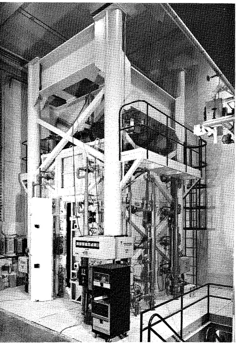
The test was carried out by exposing the column to heat in a furnace specially built for the testing of loaded columns and walls. The test furnace was designed to produce the conditions to which a member might be exposed during a fire, i.e. temperatures, structural loads, and heat transfer. It consists of a steel framework supported by four steel columns, with the furnace chamber inside the framework
(Fig. 7 ) . The characteristics and instrumentation of the furnace are
described in detail in reference 5. Only a brief description of the
furnace and the main components will
be
given here.Loading Device
Three hydraulic jacks produce forces along the three principal axes. The jack acting along the axis of the test column is located at the bottom of the furnace chamber. The plate on top of this jack can be used as a platform to which the column can be attached. No load was applied in this test.
Furnace Chamber
The furnace chamber has a floor 2642 mm ( 8 ft 8 in.) on each side
and is 3048 mm ( 1 0 ft) high. It is made of insulating materials that
will produce a high heat transfer to the specimen. There are 32 propane
gas burners in the furnace chamber, arranged in eight columns containing
four burners each. The total capacity of the burners is 4700 kW
( 1 6 million Btufh). Each burner can be adjusted individually, to obtain a high temperature uniformity in the furnace chamber. The pressure in the furnace chamber is also adjustable. It was set somewhat lower than atmospheric pressure.
Instrumentation
The furnace temperatures are measured with the aid of 8 chromel-
alumel thermocouples. The junction of each thermocouple was located
305 mm ( 1 ft) from the test specimen, at various heights. Two
thermocouples are placed opposite each other every 610 mm ( 2 ft) along
the height of the furnace chamber. The location of their junctions and
their numbering are shown in Fig. 8. Thermocouples No. 4 and 6 were
located at a height of 610 mm ( 2 ft) from the floor, thermocouples No. 2
and 8 at 1220 mm ( 4 ft), thermocouples No. 3 and 5 at 1830 mm ( 6 ft) and
thermocouples No. 1 and 7 at 2440 m ( 8 ft). The temperatures measured
by the thermocouples are averaged automatically and the average temperature is used as the criterion for controlling the furnace temperature.
The loads are controlled and measured with the aid of pressure transducers. The accuracy of controlling and measuring loads is about
Test Conditions and Procedure
The column was i n s t a l l e d i n t h e furnace by b o l t i n g i t s end p l a t e s t o a loading head a t the top and a h y d r a u l i c jack a t the bottom. Eight 19 mm (314 i n . ) b o l t s , spaced r e g u l a r l y around t h e column 63.5 nun
( 2 112 in.) from the s i d e s were used a t each end. On t h e day of the t e s t , the moisture c o n d i t i o n i n t h e c e n t e r of the column was measured with the a i d of a Monfore gauge3. The r e l a t i v e humidity p r i o r t o the s t a r t of t h e t e s t was 5%. The ambient temperature a t t h e s t a r t of t h e t e s t was 24°C (75°F).
The column was t e s t e d unloaded. The compressive s t r e n g t h of t h e c o n c r e t e on t h e day of the t e s t was not measured. The column was c a s t on t h e 27th of June 1977 and t e s t e d on t h e 19th of September 1979.
n u r i n g t h e t e s t t h e column was exposed t o h e a t i n g c o n t r o l l e d s o t h a t t h e average temperat:ure i n t h e f u r n a c e followed a s c l o s e l y a s p o s s i b l e t h e A S T M - E ~ ~ ~ ~ O r U L C - S I ~ I ~ standard temperature-time curve. This curve can be approximately described by the following equation:*
where
Tf = temperature i n "C, and
r = t i m e i n h
where
Tf = temperature i n OF.
During t h e t e s t , temperatures i n t h e furnace and i n t h e column were measured a t t h e l o c a t i o n s described e a r l i e r . The a x i a l s t r a i n of t h e
column was not measured. The t e s t was terminated 4 hours a f t e r t h e s t a r t .
TEST
RESULTSMeasured Temperatures
The temperatures measured during t h e t e s t a t v a r i o u s l e v e l s on t h e r e i n f o r c i n g s t e e l and i n t h e c o n c r e t e s e c t i o n s a r e given i n Tables 2 and 3. I n Table 2 t h e s t e e l temperatures a r e given f o r v a r i o u s times. The temperatures measured i n t h e c o n c r e t e s e c t i o n s a r e given i n Tables 3A-D. The t e s t l a s t e d 4 hours, but temperatures measured i n t h e column a f t e r
about 3 hours were n o t r e l i a b l e . T h i s was probably caused by a l a r g e a x i a l expansion of t h e unloaded column and e x c e s s i v e s t r a i n on t h e
thermocouple w i r e s i n i t . Some of t h e thermocouples were damaged d u r i n g t r a n s p o r t a t i o n of t h e column and d i d n o t f u n c t i o n from t h e beginning of t h e t e s t .
The temperatures measured i n t h e furnace a t v a r i o u s l o c a t i o n s and t h e i r average a r e g i v e n i n T a b l e 4.
Observations
H o r i z o n t a l h a i r l i n e cracks were observed on t h e s u r f a c e of t h e specimen b e f o r e t h e test. The l o c a t i o n s of t h e s e c r a c k s a r e shown i n Fig. 9.
A f t e r 90 minutes exposure, narrow l o n g i t u d i n a l c r a c k s 100-150 mm (4-6 in.) long were observed on two s i d e s of t h e column. The l o c a t i o n s of t h e s e cracks a r e shown i n Fig. 10.
Figure 11 shows t h e column i n t h e f u r n a c e chamber a f t e r t h e t e s t . The cracks i n t h e column were very narrow and do n o t show on t h e p i c t u r e .
DISCUSSION OF RESULTS
Using the method described i n r e f e r e n c e 9, t h e temperatures of t h e main r e i n f o r c i n g s t e e l , and t h e temperatures a t v a r i o u s depths i n t h e c o n c r e t e s e c t i o n s have been c a l c u l a t e d . For t h e r e i n f o r c i n g s t e e l t h e temperature a t t h e c e n t e r h a s been chosen a s r e p r e s e n t a t i v e of t h e average temperature of t h e s t e e l . This temperature has been p l o t t e d i n Fig. 12 a s a f u n c t i o n of time. It i~ compared w i t h t h e average
temperatures obtained from measurements on two r e i n f o r c i n g b a r s during t h e t e s t . These measurements were made w i t h thermocouples No. 3 and 9, l o c a t e d o p p o s i t e each o t h e r w i t h r e s p e c t t o t h e c e n t e r of one b a r , and w i t h thermocouples No. 4 and 10, l o c a t e d o p p o s i t e each o t h e r on a n o t h e r bar (Fig. 6). The comparison between measured average s t e e l
temperatures and t h e temperatures i n t h e c o n c r e t e s e c t i o n a t t h e c e n t e r of t h e s t e e l , c a l c u l a t e d according t o t h e method d e s c r i b e d i n r e f e r e n c e 9, shows a good agreement between measured and c a l c u l a t e d temperatures.
The temperatures measured on t h e s t e e l by t h e i n d i v i d u a l thermocouples a r e shown i n Pig. 13. The d i f f e r e n c e i n temperature between two o p p o s i t e p o i n t s of t h e bar is r e l a t i v e l y snall.
I n Fig. 14 t h e temperatures shown a r e measured along a c e n t e r l i n e i n t h e c o n c r e t e s e c t i o n a t v a r i o u s depths and column h e i g h t s . For a s p e c i f i c depth, t h e d i f f e r e n c e s i n temperature between t h e v a r i o u s h e i g h t s a r e small. The s m a l l d i f f e r e n c e s i n d i c a t e t h a t h e a t t r a n s f e r from the furnace t o t h e column i s uniform.
I n Fig. 15 temperatures c a l c u l a t e d f o r t h r e e depths a r e compared w i t h t h e average of t h e temperatures measured a t t h r e e h e i g h t s a l o n g t h e c e n t e r l i n e of t h e column s e c t i o n s .
I n Fig. 16 a s i m i l a r comparison i s made f o r t h e temperatures a l o n g t h e d i a g o n a l of t h e column s e c t i o n s .
The curves show a good agreement between measured and c a l c u l a t e d temperatures, w i t h t h e exception of t h o s e a t 38 mm (1 112 in.) depth along t h e diagonal of t h e column s e c t i o n . I n t h i s c a s e t h e d i f f e r e n c e s between t h e measured and t h e c a l c u l a t e d temperatures a r e about 15% i n t h e h i g h e r temperature range. Taking i n t o account, however, t h a t t h e r e a r e d i f f e r e n c e s of more t h a n 20% between t h e i n d i v i d u a l temperatures measured a t t h i s depth, a d i f f e r e n c e of 15% is not s i g n i f i c a n t .
REFERENCES
1. Standard Practice for Petrographic Examination of Aggregates for
Concrete, (1979). ASTM C295-79, American Society for Testing and
Materials, Philadelphia.
2. Standard Specification for Deformed and Plain Bullet-Steel Bars for
Concrete Reinforcement. (1980). ASTM A615-80, American Society for
Testing and Materials, Philadelphia.
3. Monfore, G.E. (1962).
A
Small Probe-Type Gauge for MeasuringRelative Humidity. Journal of the PCA Research and Development
Laboratories, Vol.
5,
No. 2.4.
Reinforcing Steel Welding Code, (1975). AWS-D12.1-75, AmericanWelding Society, Manlius, NY.
5. Lie, T.T. (1980). New Facility to Determine Fire Resistance of
Columns, Canadian Journal of Civil Engineering, Vol. 7, No. 3.
6. Standard Methods of Fire Tests of Building Construction and
Materials. (1979). ANSIIASTM El 19-79, American Society for Testing
and Materials, Philadelphia.
7. Standard Methods of Fire Endurance Tests of Building Construction
and Materials, (1980). ULC-S101-Ml980, Underwriters' Laboratories
of Canada, Scarborough, Ontario.
8. Lie, T.T. and Harmathy, T.Z. (1972). A Numerical Procedure to
Calculate the Temperature of Protected Steel Columns Exposed to Fire, Fire Study No. 28, Division of Building Research, National Research Council Canada, Ottawa, NRCC 12535.
9. Lie. T.T., Allen, D.E., Lin, T.D. and Abrams, M.S. Fire Resistance
of Reinforced Concrete Columns, Division of Building Research, National Research Council Canada, Ottawa, to be published.
TABLE 1 PETROGRAPHY OF SAND AND GRAVEL USED AS AGGREGATE
Composition of S i e v e F r a c t t o n , P e r c e n t on S i e v e of S i z e I n d i c a t e d P e r c e n t
Component P a s s i n g
19mm 12.5mm 9.5mm 6 mm No. No. No. No. No. No. No. t h r o u g h
4 8 16 30 50 100 200 No. 200
--
G r a n i t e 37.9 32.9 25.5 31.3 27 .O 27.6 12.3 7.4 1.9 4.4 0.6--
Q u a r t z i t e 21.6 29.2 34.8 24.6 24.5 20.0 12.3 12.6 10.9 3.1 2.2--
Quartz 6.3 3 1 4.9 4.8 5.5 18.8 52.2 62.0 73.1 79.5 74.2 92.0 Sandstone-Quartz Conglomerate 1.9 0.8 3.1 5.1 5.5 8.3--
--
--
--
--
--
R h y o l i t e - D a c i t e 13.9 6.2 2.2 5.1 7.2 4.1 0.8 2.6 1.6 0.8 0.9--
F e l d s p a r--
--
--
--
--
--
1.3 5.0 6.6 5.0 10.8 4.0 D i o r i t e 1.9 1.4 3.1 1.8 1.2--
--
--
--
--
--
--
Graywacke b 1.3 9.5 5.8 5.4 4.3 6.5 2.3 1.5 0.3--
0.6--
Gneiss-Schist 2.5 5.1 10.5 9.3 7.5 4.1 6.4 1.8 0.9 1.1 0.6--
B a s a l t 1.9 4.5 4.0 3.9 6.9 3.2 2.6 2.4 0.7--
0.3--
Mist. I g n e o u s Rocks and Opaque M i n e r a l s--
0.3 0.9 0.6 0.6 1.5 2.1 1.2 2.0 5.3 7.0 2.0-
P a r t i c l e Shape 1 9 t o 6 mm ( % ) No. 4 t o No. 1 6 ( % ) No. 30 t o No. 2 0 0 ( % )
Subrounded t o rounded 30 20 1 0
Subrounded t o s u b a n g u l a r 40 40 40
Angular 30 4 0 5 0
a " ~ r o n s t o n e , " made up of j a s p e r and h e m a t i t e , i s i n c l u d e d i n t h e c h e r t c l a s s i f i c a t i o n . b ~ n c l u d e s metagraywacke.
?he m i s c e l l a n e o u s i g n e o u s roclcs were s e v e r e l y a l t e r e d and p o s i t i v e i d e n t i f i c a t i o n was i m p o s s i b l e . The opaque m i n e r a l s o c c u r r e d i n t h e No. 50 and s m a l l e r s i e v e s i z e s and were l a r g e l y m a g n e t i t e .
TABLE 2 MEASURED STEEL TEMPERATURES
T e m p e r a t u r e (OC) M e a s u r e d a t
T h e r m o c o u p l e N o : T i m e
TABLE 3A CONCRETE TEMPERATURES MEASURED WITH THERMOCOUPLES I N FRAME A T e m p e r a t u r e (OC) Measured a t Thermocouple No: Time ( m i d 1 1 12 1 3 14 15 16 17 1 8 19 20 21 22 2 3 24 0 24 24 24 24 24 24 24 24 24 24 24 24 24 24 5 107 8 2 54 4 1 27 27 27 27 27 24 4 1 24 4 3 6 3 10 204 154 99 60 35 27 27 27 38 46 93 93 129 218 1 5 307 238 152 99 52 29 27 29 54 9 3 124 1 6 3 224 357 20 391 307 199 132 71 35 29 35 88 121 160 241 316 468 2 5 460 366 249 166 110 4 3 3 2 49 110 177 210 307 393 541 30 516 421 293 199 113 77 46 93 121 224 260 366 454 602 3 5 557 463 329 232 121 107 6 6 107 1 3 8 268 304 391 502 643 40 593 502 363 260 141 110 79 110 157 307 357 463 549 677 4 5 613 521 388 277 154 1 1 0 99 1 1 0 177 3 3 5 379 496 588 713 50 649 557 418 310 171 110 107 110 199 363 418 529 627 741 5 5 668 574 443 324 191 110 107 110 218 391 438 560 660 760 60 691 604 468 354 204 1 1 8 107 113 243 416 468 588 688 782 6 5 718 629 488 379 221 129 107 127 266 438 502 616 710 799 70 729 643 510 391 241 135 107 135 285 460 516 641 732 8 1 0 75 746 668 527 413 254 154 107 152 307 477 538 660 749 829 8 0 760 677 543 427 271 163 110 166 327 499 552 685 766 846 8 5 774 696 560 449 288 177 124 177 343 516 577 702 779 857 90 785 704 577 460 299 1 8 8 138 191 363 532 591 718 793 866 9 5 799 721 5 9 3 479 316 204 149 204 379 549 610 732 802 8 7 1 100 804 729 607 488 329 213 160 218 399 566 621 746 816 879 1 0 5 816 746 621 507 343 232 171 229 416 582 641 760 824 885 110 824 752 635 516 357 235 182 243 429 599 649 768 829 8 9 1 115 838 766 646 532 371 252 196 254 446 613 668 771 832 8 9 1 120 841 771 660 541 385 260 204 266 474 627 677 771 818 885 1 3 0 857 788 682 566 413 285 232 293 491 654 699 752 774 8 4 1 140 871 8 1 3 699 593 438 316 254 321 516 657 727 746
*
787 1 5 0 882 8 2 1 713 610 460 329 277 346 538 713 741*
*
768 160 891 835 721 632 482 354 302 366 563 729 757*
x*
170 902 846 732 652 507 377 324 391 588 729*
*
*
*
180 913 8 6 3 741 677 529 407 346 413 613 760*
x x x *Measurement n o t r e l i a b l eTABLE 3B
CONCRETE TEMPERATURES MEASURED WITH THERMOCOUPLES IN
FRAMEB
- -- - - Temperature ( O C ) Measured a t Thermocouple No: Time (min)25
26
27
28 29
30
31
32
33
34
35
36
37
38
0
24
24
24
24
24
24
24
24
24
24
24
24
24
24
5
141 121
*
x*
24
24
24
24
27
43
60 82 121
10
316 243
*
38
*
24
24
24
27
49
93 127 218 302
15
468 379
*
82
*
24
24
24
38
93 163 224 360 468
20
566 482
*
124
93
27
27
27
82 121 241 318 466 560
25
629 560
*
163
99
49
27
38
99 179 307 393 541 643
30
677 618
*
196
99
54
29
57 102 224 366 454 599 691
35
716 657
*
224
99 60 43
85 113 268 418 502 691 727
40
752 699
*
254 110
77
60 99 143 307 460 549 679 754
45
777 727
*
277 127 91 77
99 168 338 496 588 713 782
50
802 754
*
302 143
99 99 99 191 363 529 627 743 804
55
821 779
*
324 160 102
99 102 213 391 560 660 763 824
60
838 799
*
343 174 107
99 113 238 416 588 685 782 838
65
852 816
*
366 193 116
99 121 260 438 616 710 799 852
70
860 827
*
385 210 129
99 135 282 460 641 732 813 860
75
871
*
*
402 227 143 107 146 302 477 660 749 829 871
80
877
*
*
418 246 157 118 160 321 499 682 766 846 877
85
885
*
*
435 260 168 127 177 343 516 699 777 857 885
90
891
*
*
454 274 182 138 188 360 532 718 793 866 891
95
893
*
*
468 291 193 149 202 377 543 732 802 874 893
100
896
*
*
482 307 207 163 218 393 566 746 816 879 896
105
902
*
*
499 324 224 174 235 413 582 760 824 885 902
110
913
*
*
510 338 235 188 263 432 599 768 829 891 913
115
918
*
*
521 352 249 199 302 446 613 771 829 891 918
120
921
*
*
532 368 260 213 371 468 627 771 816 885 921
130
927
*
*
557 393 293 238 532 532 654
*
*
r~*
140
927
*
*
582 421 327 260 635 621 685
*
x*
x150
929
*
*
607 449 371 288 691 682 710
*
*
*
*
160
932
*
*
638 477 421 313 718 718 732
*
*
*
*
170
935
*
*
663 516 474 343 746 732 746
*
*
*
*
180
932
*
*
688 552 513
*
754 743 754
*
*
*
*
TABLE 3C CONCRETE TEMPERATURES Mi?ASURED WITH THERMOCOUPLES I N FRAME C
- -
Temperature (OC) Measured a t Thermocouple No: Time (min) 39 40 41 42 43 44 45 46 47 48 49 50 51 52 0
*
*
5*
*
10*
*
1 5*
*
20*
*
25*
*
30*
*
3 5*
*
40*
x 4 5*
*
50*
*
5 5*
*
60 x*
6 5*
*
70*
x 7 5*
*
80 x*
8 5*
x 90 x rt 9 5*
*
100*
*
105*
*
110*
*
115*
x 120*
*
130*
*
140*
*
150*
*
160*
*
170*
x 180*
*
*Measurement n o t r e l i a b l eTABLE 3D CONCRETE TEMPERATURES MEASURED WITH THERMOCOUPLES IN FRAME D Temperature
('c)
Measured a t Thermocouple No: Time (min) 53 54 55 56 57 58 59 60 61 62 63 64 65 66 "Measurement not r e l i a b l eTABLE
4
EVRNACE TEMPERATURESTemperature ('C) Measured a t
Thermocouple No: Average
Time Temperature
m m
m m m m S T A N D A R D S I Z E O F S Q U A R E M E S H S I E V EF I G U R E 1
P L A T E
P L A T E
F I G U R E 2
TIC
F R A M E A1-d-1
S E C T I O N A - A - .-TIC
F R A M E B O N B A C KTIC
F R A M E C O N F R O N T - S E C T I O N B - BTIC
F R A M E O-, S E C T I O N C - C H = 3 8 1 0 rnrn F I G U R E 3 L A Y O U T O F T H E R M O C O U P L E F R A M E STIC
FRAME 17 16 15 14 13 12 11 A 31M
29 28 27 26 25B
45 44 43 42 4140
39 C 59 5857
56 55 54 53 D F I G U R E 4 L O C A T I O N A N D N U M B E R S OF T H E R M O C O U P L E S I N A S E C T I O N1 4 8 mrn CLEAR COVER TO MAIN REINFORCING BAR
T 1 c 4 4 ~ ~ ~ ~ ~ 7 & T 1 3 5 mrn
'TIC
1, 2, 3, 99 5 rnm 533 x 533 x 25 rnm
THICK STEEL PLATE 7
F I G U R E 5
F I G U R E 6
FIGURE 7 TEST FURNACE
T O P V I E W D O O R ( E A S T S I D E ) F I G U R E 8 L O C A T I O N A N D N U M B E R S O F T H E R M O C O U P L E S I N C O L U M N F U R N A C E C H A M B E R
EAST
N O R T HWEST
S O U T HVlEW
W&VF I G U R E 9
F I G U R E 10
L O N G I T U D I N A L C R A C K S O N C O L U M N N O . 1 A T 90 rnin
FIGURE 11
CALCULATED
M E A S U R E D . AVERAGE T/C 3 . 9 8 0 0 MEASURED. AVERAGE T/C 4 . 1 0
T I M E . rnin
F I G U R E 1 2
CALCULATED A N D M E A S U R E D AVERAGE TEMPERATURES OF M A l N R E I N F O R C I N G B A R S 0 0 4 0 80 1 2 0 1 6 0 2 0 0 T I M E . rnin 800 F I G U R E 1 3 TEMPERATURES M E A S U R E D O N M A I N R E I N F O R C I N G B A R S
-
THERMOCOUPLE N O . : - ---- 3-
--
4-
9 - -.--.. 3-
Q w w 400 - - u +. . 2 0 0 --
-314 H E I G H T M I D - H E l L N i 800 114 H E I G H T T I M E , siiin F I G U R E 1 4 T E M P E R A I U R E S M E A S U R E D I N L O N L R E i E i E C T l O N ALONG CENTRELINE AT V A R I O U S DEPTHS A N 0 C O L U M N H E I G H T S ..--.- M E A S U R E D I A V E R A G E I 0 4 0 8 0 1 2 0 1 6 0 T I M E . m l n F I G U R E 15 C O N C R E T E T E M P E R A T U R E S I N S E C T I O N A L O N G C E N T R E L I N E A T V A R I O U S D E P T H S
...M E A S U R E D I A V E R A G E I - C A L C U L A T E D