Publisher’s version / Version de l'éditeur:
Vous avez des questions? Nous pouvons vous aider. Pour communiquer directement avec un auteur, consultez la première page de la revue dans laquelle son article a été publié afin de trouver ses coordonnées. Si vous n’arrivez pas à les repérer, communiquez avec nous à PublicationsArchive-ArchivesPublications@nrc-cnrc.gc.ca.
Questions? Contact the NRC Publications Archive team at
PublicationsArchive-ArchivesPublications@nrc-cnrc.gc.ca. If you wish to email the authors directly, please see the first page of the publication for their contact information.
https://publications-cnrc.canada.ca/fra/droits
L’accès à ce site Web et l’utilisation de son contenu sont assujettis aux conditions présentées dans le site LISEZ CES CONDITIONS ATTENTIVEMENT AVANT D’UTILISER CE SITE WEB.
Journal of Thermal Spray Technology, 29, 1-2, pp. 134-146, 2019-12-02
READ THESE TERMS AND CONDITIONS CAREFULLY BEFORE USING THIS WEBSITE. https://nrc-publications.canada.ca/eng/copyright
NRC Publications Archive Record / Notice des Archives des publications du CNRC :
https://nrc-publications.canada.ca/eng/view/object/?id=a389656d-5304-4ec7-bafe-ac0413e990c5
https://publications-cnrc.canada.ca/fra/voir/objet/?id=a389656d-5304-4ec7-bafe-ac0413e990c5
NRC Publications Archive
Archives des publications du CNRC
This publication could be one of several versions: author’s original, accepted manuscript or the publisher’s version. / La version de cette publication peut être l’une des suivantes : la version prépublication de l’auteur, la version acceptée du manuscrit ou la version de l’éditeur.
For the publisher’s version, please access the DOI link below./ Pour consulter la version de l’éditeur, utilisez le lien DOI ci-dessous.
https://doi.org/10.1007/s11666-019-00967-w
Access and use of this website and the material on it are subject to the Terms and Conditions set forth at
Observation of an indirect deposition effect while cold spraying Sn-Al
mixed powders onto carbon fiber reinforced polymers
Observation of an Indirect Deposition Effect while Cold Spraying
Sn-Al Mixed Powders onto Carbon Fibre Reinforced Polymers
Mr. Andre C. Liberati1*, Dr. Hanqing Che1*, Dr. Phuong Vo2, Prof. Stephen Yue1
1Mining and Materials Engineering, McGill University, Montreal, QC, Canada 2National Research Council Canada, Boucherville, QC, Canada
*Corresponding authors :
Email address : hanqing.che@mail.mcgill.ca (H.Che), andre.liberati@mail.mcgill.ca (A. Liberati)
Keywords: Cold spray, Indirect Deposition, Carbon Fibre Reinforced Polymers, Mixed Metal Powders, Metallization of Polymers,
Computational Fluid Dynamics (CFD)
Abstract
Single component tin coatings have successfully been cold-sprayed onto carbon fibre reinforced polymers (CFRPs) in previous studies at McGill University. Coatings with mixed metal powders were also sprayed to improve the deposition efficiency and coating conductivity. Results indicated a noticeable improvement in deposition efficiency (DE) related to the addition of a secondary metallic powder (aluminum, copper and zinc); this study is focused on the effect of aluminum. Following cold spray of various Sn/Al mixtures over a wide range of gas pressures, unusual coating morphologies were observed. The study of these morphologies leads to the description of two distinct deposition phases depending on the spray pressure: a direct deposition effect and an indirect deposition effect. The presence of submicron particles also supports the occurrence of a powder melting phenomenon during the process. Numerical simulations were conducted to support the description of these phenomena.
Introduction
CFRPs are poor electrical conductors – the carbon fibres are approximately 1,000 times more resistive than aluminum to current flow and epoxy resins are 1,000,000 more resistive [1] – so they are prone to damage from lightning strikes
that aircraft endure once per year on average [2]. To improve their conductivity while maintaining low densities, “metallizing” or applying metallic coatings to composites such as CFRPs has received increasing interest, but these coatings still suffer from poor quality (porosity, adherence [3], conductivity [4], etc.). “Metallization” can be achieved through a series of approaches, such as lay-up molding [5] or arc spray [6], but cold-spray appears as a legitimate alternative [7-11] since it uses relatively low temperatures (several hundred versus several thousand degrees for other techniques), thus limiting the risk of oxidation of the metallic powder particles and the heat damage of the substrate [7].
Coating on this substrate through cold-spray has been tried and mixed results have been obtained regarding the erosion of the soft substrate due to the higher hardness of most metallic powders [9, 12, 13]. Nonetheless, some researchers have encountered success in depositing tin particles on polymeric substrates [8-10] all while recording relatively low deposition efficiencies (DE) (i.e. the ratio of effectively deposited particles on the substrate versus the amount of sprayed particles). This was associated with a “crack filling” mechanism described by Che et al. [9], where thermally softened or partially melted tin particles were suspected to impact the substrate, and while the harder core of the particle would generate micro-cracks in the CFRP substrate, the softer outer-core would immediately fill the cracks and provide mechanical interlocking with the substrate. This was supported by microstructural observations and by using process temperatures of 280°C or 300°C, quite largely above the melting point of tin (232°C) [9]. The seemingly small increase in temperature (from 280°C to 300°C) seemed to enable the “crack filling” mechanism, as deposition was almost inexistent at 280°C yet took place at 300°C.
In parallel, several researchers have proven that the deposition of a coating on a substrate can be enhanced by mixing ceramic powders in the feedstock powder, which will produce a shot-peening effect on the relatively softer feedstock powder and produce better coatings [14-16]. Che et al. [17] observed a similar improvement of the coating deposition process when mixing metallic powders (zinc or copper) with tin powders. This improvement was associated with the tamping effect of the secondary component on the relatively softer tin. In a previous study [18], the addition of aluminum to feedstock tin powder was shown to also improve the DE of a pure tin coating, but while the DE trend for tin, mixed tin-zinc and tin-copper powders seemed quite clear (decreasing for the chosen pressure values [9,17]), mixed
tin-aluminum powders presented an increasing DE trend; however, only few spray parameters were tested, so a maximum DE value for tin-aluminum mixed powders was not located.
In this present study, mixed tin-aluminum powder was cold-sprayed on CFRP and mild steel substrates over a wide range of carrier gas pressures to corroborate and expand on the results of [18]. Tin-aluminum mixed powder with a 90:10 weight ratio was cold-sprayed onto a thermosetting epoxy CFRP substrate at various process conditions with a low-pressure cold spray system. Microanalysis of the coatings was then performed and the deposition mechanism of the mixed powders on CFRPs is discussed, namely for higher pressures where an unusual coating morphology was observed. The DE was also measured and a discussion on the variation of the DE is proposed. Given the absence of references supporting such a coating morphology, a simple 3D model was established based on the parameters chosen in recent computational fluid dynamics (CFD) models, destined to optimize cold-spray parameters [19-23]. The purpose of this model was to simulate the flow of particles in the cold spray process and study the metrics of the powders (namely trajectory, velocity and temperature) as they impinge the substrate surface, and therefore support the mechanisms advanced to explain the observed coating structures.
Experimental Methods
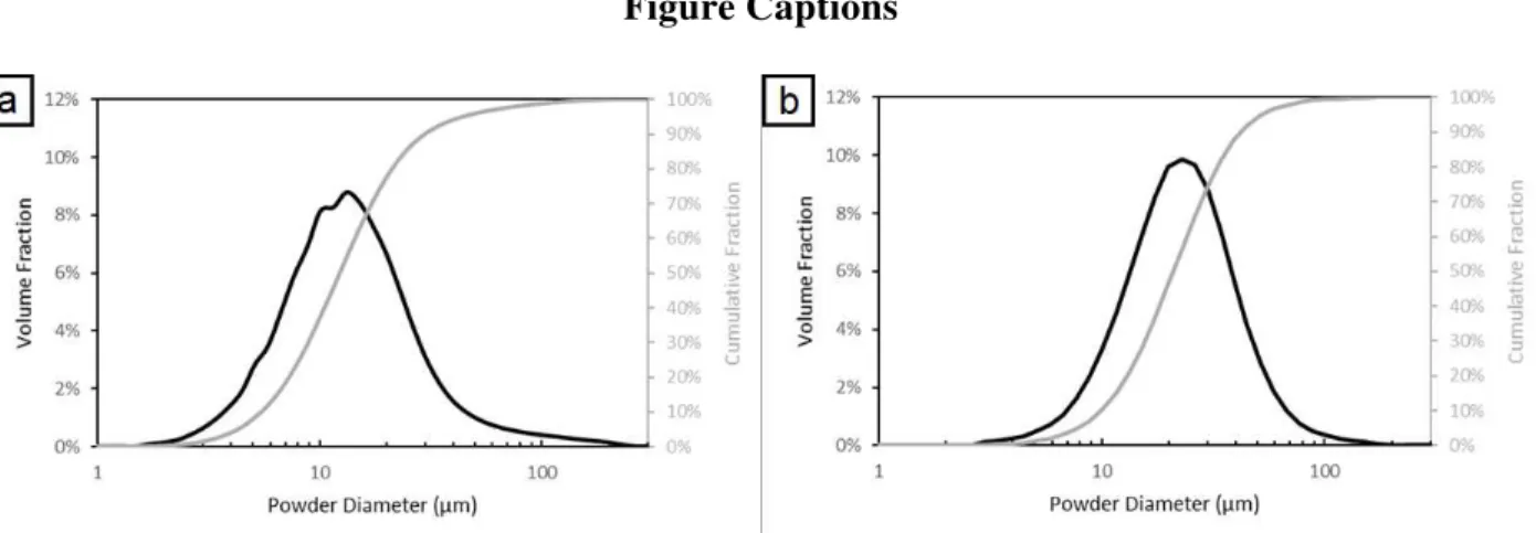
The feedstock materials used in this work are listed in Table 1. The particle sizes of the feedstock powders were measured with a laser scattering particle size analyzer (LA-920, HORIBA, Japan) and their distribution is presented in Fig. 1. The tin powder was relatively spherical and had a broad monomodal and non-symmetrical distribution, whereas the aluminum powder, which was also spherical, had a more continuous size distribution with a higher average particle size. The average Vickers hardness of the feedstock powders was measured by mounting the powders and by using a Clark CM-100AT Microhardness Tester (Sun-Tec, Novi, USA) for a penetration time of 15 s under a load of 10 gf: the hardness of the aluminum powder was more than double that of the tin powder. Both powders were of commercial purity. The scanning electron microscope (SEM) images of the single component powders are presented in Fig. 2. The powders were mixed in a metallic can without additional media (e.g. milling balls) with a double movement powder mixer for 1h. No significant morphological changes or hardening were noticed in the mixed powder when compared with the starting powders : the absence of morphological changes was verified through SEM imagery of the mixed powders and the hardness of the mixed powders was measured as per the hardness for the initial feedstock powders.
The substrates used in this work were CFRPs provided by Bombardier Aerospace (Montreal, Canada) and 1020 mild steel plates. The steel substrates were used as a benchmark to compare the spraying of powders on CFRPs to a typical metal-metal cold-spraying situation. The CFRP material used here consists of a thermosetting epoxy matrix with continuous carbon fibre reinforcements. The CFRP-panels were made of four plies of epoxy/carbon fibre prepreg ([0/90]2s) and have a coating finish used by the manufacturer. Sheet sections of dimensions 7 x 3 cm were used as
substrates during the cold spray campaigns. The substrates were degreased with acetone and the mild steel plates were grit-blasted with 24 grit alumina before cold-spraying. The CFRP substrates were not grit-blasted as it would result in the erosion of the substrate.
The cold spraying was performed at the McGill-NRC cold spray facility at National Research Council Canada in Boucherville. The cold spraying was performed at low pressure with a commercially available CenterLine SST system (Supersonic Spray Technologies, CenterLine Windsor Limited, Canada). This choice enabled the use of the so-called “downstream injection” mode, where the particles were injected in the main gas stream after the throat of the nozzle. The risk of clogging the nozzle when using metals with low melting points, such as tin, was thus reduced. The primary cold spray parameters are listed in Table 2. These parameters were chosen based on previously successful cold-spray campaigns with tin [9, 17], and a wider range of carrier gas pressures was chosen expand on the results of [18] and determine a maximum DE value for the deposition of mixed tin-aluminum powders. The carrier gas was nitrogen, the stand-off distance was 18 mm and the gun travel speed was 25 mm/s. The powder feeder rate was set to 1 revolution per minute (RPM), which gave a measured feeding rate of 11.5 g/min. Only one pass was sprayed for each set of conditions, with a step size of 1 mm (18 steps), so that the average DE from a large area, together with a study focused on the DE trend, would be meaningful.
Deposition efficiency was measured as the mass gain of the substrate divided by the total mass of feedstock powder fed during the time the gun was over the substrate. After the cold spray process, the samples were observed from a top-surface view then prepared as metallographic samples and characterized with a Hitachi SU3500 Scanning Electron Microscope. The cross-sectional samples were cut and observed parallel to the gun spraying direction. A 3D-Optical Surface Profiler (ZYGO, Connecticut, USA) was also used to measure the surface roughness and support large-scale
microstructural observations. On each sample, twelve areas of 3 x 3 mm were analyzed to determine the average surface roughness. The main measurements were carried out around the root mean square roughness Sq and the root mean square gradient of the surface Sdq as they provide insight into the topography of the surfaces regarding not only height but also gradient [24, 25]. More specifically, these parameters offer more detailed information on the surface conditions as compared to the average surface roughness (Sa) as Sq includes Sa and the standard deviation of the roughness as per the definition of the root mean square, and Sdq is affected both by texture amplitude and spacing, therefore Sdq can provide information on the slopes which comprise the surface in the case of coatings with similar values of Sa [24].
ANSYS Fluent (v19.3.0) was used to carry out CFD simulations, based on simulations previously made in the cold-spray field [19-23], and process parameters were chosen to be as close as possible to the system parameters used in this study. The following is a list of the modules and parameters chosen in the software – further understanding on them can be acquired from the Fluent User’s Guide [26]. The nitrogen carrier gas was set to be an ideal gas and a steady-state solution for the gas flow was calculated with a density-based solver [19, 20]. Flows were modelled in 3D to account for the downstream lateral injection that the Centerline SST system offers and that simpler 2D-axisymettrical models cannot account for. The structured mesh was developed with approximately 111 000 elements with refinement around the key elements of the system (nozzle throat, powder injection nozzle, nozzle exit, “substrate” wall) to better account for thermodynamic property changes associated with gas expansion. The final mesh can be observed in Fig. 3. The Navier-Stokes equations for mass, momentum and energy of the gas flow were solved for a steady state in their Reynolds-averaged form and, consequently, extended by a standard k-ε turbulence model with standard wall functions [20]. Two-way coupling systems with advanced turbulence models can be implemented to provide more accurate simulations [21] but given the dilution of the powder in the gas flow (solid phase volume fraction <10%), it can be assumed that particle-particle and particle-gas interactions are negligible [19, 22] and a Lagrangian (one-way coupling) solution is sufficient to study particles in the flow. The Discrete Phase Model algorithm can be assumed to be accurate [19] and a face normal injection of 20-µm tin powders in the gas flow was implemented at the powder injection point. To account for particle dispersion associated with turbulence effects, the Stochastic-Tracking type model is activated and the Discrete Random Walk model is used to predict the fluctuating components of the total particle velocity and effects on its trajectory [19, 26]. Finally, boundary conditions are set as indicated on
Fig. 3 : the gas inlet is defined as a pressure inlet with two sets of conditions (320°C/60psi and 320°C/150psi), the powder inlet is defined as a pressure inlet with a pressure of 14.5psi (=0.1MPa) to 43.5psi (=0.3MPa) to assist the injection of powder in the system and avoid potential expulsion of powders before their injection during calculation, the gas outlet is defined as an atmospheric pressure outlet located far enough from the nozzle exit to avoid unrealistic settings [19] and the nozzle wall was set as an adiabatic no-slip boundary. The substrate is defined as a wall and interactions with it are neglected: particles are supposed to rebound on the substrate without energetic loses.
Results
Figure 4 shows the DE of the mixed powder Sn-10Al on different substrates at 300°C and 320°C as a function of the gas pressure. Coating deposition on steel was achieved for all conditions, while deposition on CFRP was irregular in some cases, namely higher pressures. While the DE on steel provides one maximum for both spray temperatures (around 70 psi), the DE on CFRP seems to provide a local maximum (around 70 psi) then a plateau regime with increasing pressure. Note that previous spraying of single component aluminum on CFRPs generated no deposition because of erosion, whereas pure tin generated a coating with a maximum DE of 20% [9].
The retention rates of aluminum in the CFRP coatings were measured in the cross-section for several coating conditions (60 psi at 300°C and 60, 80 and 100 psi at 320°C). These rates were estimated by measuring the relative areas of tin and aluminum in SEM BSE-COMP images using an image analysis method. From these retention rates, the DE of each pure element in the coating can be calculated with the following expressions:
��=���∗.
��= − ���. �∗
where DE, DEAl and DESn are respectively the overall DE of the coating, pure Al and pure Sn and rAl is the weight
fraction of Al in the coating. Coating thickness was also measured with these cross-sectional micrographs. The results are listed in Table 3. The retention rates in the coating are very low compared to the initial 10% of aluminum in the powder mix. For the coatings at 60 psi, variations are observed in the overall DE, the DE of pure tin and the thickness of the coating while the retention rates of aluminum remain close to 0%. With increasing pressure at 320°C, the overall DE, the DE of pure tin and the coating thickness decrease while the retention rate of aluminum increases. Nevertheless,
the effective DE of pure aluminum remains relatively low (under 20% of the initial aluminum input). The cross-sectional micrographs of the mixed powder coatings sprayed for these conditions are presented in Fig. 5. These coatings are relatively dense with small defects mainly localized around the aluminum particles and only a small number of aluminum particles are noticeable in the coatings, which exemplifies the low retention rates of aluminum. More noticeably, the number of aluminum particles barely increases with increasing pressure at 320°C, while the thickness of the coatings decreases (from 290 to 70 µm) as does the overall DE (from 24% to 6%) and the DE of pure tin (from 27% to 7%). Therefore, there does not seem to be an obvious relation between aluminum retention and overall DE. The area around the top surface seems to indicate more roughness with higher pressures as can be seen in Fig. 5 d.
The latter phenomenon can be better visualized with low-magnification top-surface images of the coatings as seen in Fig. 6. This figure shows an evolution of the coating with increasing pressure while cold-spraying at 300°C. For pressures below 60 psi (Fig. 6 a), a relatively uniform and even surface is obtained. For pressures around 80psi (Fig. 6 b), small agglomerations of powder can be observed and finally, for relatively higher pressures (Fig. 6 c-d), larger dendrite-like protrusions are observable. On another note, the carbon fibre matrix is apparent for very high pressures, as indicated by the white arrow in Fig. 6 d, revealing erosion of the CFRP. The previously described protrusions at higher pressures are also clearly visible to the naked eye as shown in Fig. 7. These protrusions have the same direction as the spray gun as it descends on the CFRP substrate, but they are not noticed on any of the steel substrates. Fig. 7 also reveals a strong difference in deposition throughout the substrate depending on the considered area: in the vicinity of the last spray step, there is no coating on the substrate (the carbon fibre matrix is visible) whereas in previously sprayed areas there are the previously discussed protrusions. Below the last spray step, some powder agglomerates can also be noticed. This behavior is representative of all higher pressure cold-sprayed CFRP substrates (above 100psi). The coatings at 320°C follow the same structural evolution with increasing pressure. Aluminum retention in the top surface is quite negligible.
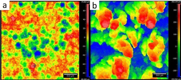
Height profiles of areas similar to the low-magnification microstructures presented in Fig. 6, are presented in Fig. 8, to support the macro- and microscopic observations. For lower pressures (Fig. 8 a), the surface roughness is low (Sa < 20μm), the maximum height of the areal surface remains within 100-200μm (several times the diameter of the feedstock powder) and the craters generated by impinging powders on the substrate are visible. For higher pressures
(Fig. 8 b), surface roughness is higher (Sa >100μm), the maximum height of the areal surface is above 500μm and the previously discussed protrusions appear clearly. For the CFRP coatings at 320°C similar observations are made, whereas for steel substrates, the height profiles are fairly similar to the case of lower pressure CFRP height profiles (Fig. 8 a). The graph presenting Sq as a function of pressure is presented in Fig. 9: Sdq presents the same evolution as Sq. These graphs reveal low roughness values of for both substrates at pressures below 70 psi, and at higher pressures, the roughness values remain low for the steel substrate while an increase is observed for the CFRP substrates.
With higher magnification SEM images of the CFRP coatings at 300°C, tin powders can easily be observed for lower pressures . These particles show minimal deformation and sizes ranging from 10 to 20 µm which is relatively similar to the initial feedstock powder (Fig. 2 a). For higher pressures, these particles become less and less discernable. Some larger particles may be observed with intermediate pressures but generally only particles around 5-10 µm are observed on the top surface. With higher pressures (over 100psi), small satellites are observed throughout the top surface and cover the few powders that can be seen. At 150psi, these satellites almost completely cover the top surface. Again, the coatings at 320°C follow the same structural evolution with increasing pressure. Higher magnification images of the high-pressure coatings reveal that the small satellites are small tin particles generally smaller than 1 µm, as seen in Fig. 10. As opposed to the feedstock powder (Fig. 2 a), these particles are spherical and are not representative of the powder distribution results. It is important to note that the detection limit of the Horiba LA-920 is 0.02 µm and in the particle size distribution of the feedstock tin powder, no powders smaller than 1.5 µm are detected.
Discussion
The content of aluminum in the studied coatings is far lower than the initial aluminum input, as noted when studying the retention rates and resulting DE of aluminum in Table 3. An increasing fraction of aluminum was noticeable in the coatings at 320°C, but the DE of aluminum hardly increased and only the tin content in each coating noticeably evolved, which suggests that the evolution of the overall DE is related to the actual deposition of tin and not the aluminum. Therefore, there seems to be no relation between the cold spray conditions and aluminum retention here as already noted by Liberati et al.[18]. A thorough study of the steel cross-sections would be interesting to compare the retention of aluminum in the steel coatings.
The maximum DE value of pure tin at 300°C (15%) in previous work [9] is higher than that of Sn-10Al at 300°C (8%) measured in this work, while Al was expected to help increase the maximum DE as in [18] (obtained maximum DE of 20%). This increase was nevertheless observed at 320°C, where the maximum of Sn-10Al is 25%. Furthermore, the DE of Sn-10Al at 300°C and 320°C follow a similar trend with increasing pressure as the DE of pure tin on CFRP from [9], but they do not follow the same increasing trend observed in [18]. Therefore, the current results do not allow us to corroborate the results from [18] as initially intended. These differences could be related to process fluctuations between studies. Further experiments comparing pure tin and mixed metal powders such as tin-aluminum should be conducted to determine the effect of the secondary component with better comparability.
On another note, certain trends seem to stand out when comparing the DE results of this study with the obtained macro- and microstructures. For lower pressures (below 60 psi), the obtained coatings seem to be quite uniform with relatively higher DE and dense, uniform coatings (Fig. 6 a, Fig. 8 a). For intermediate pressures (70-80psi), the coatings tend to be thinner with lower DE and the appearance of small agglomerates on the top surface. For higher pressures (above 100 psi), DE slightly increases then plateaus, but deposition is very inconsistent: two areas clearly stand out from a macroscopic point of view with an area presenting dendrite-like protrusions that follow the same direction as the gun displacement (Fig. 6 d, Fig. 8 b) and another area, directly below the last spray step, that presents very poor deposition and exposure of the carbon fibres (indicative of a non-negligible amount of substrate erosion). The acquired roughness data (Fig. 9) supports this microstructural evolution and shows that with increasing pressure, coatings on the CFRP present increasing roughness and gradients that are significant of steeper peaks and can be related to the appearance of the high-pressure protrusions. Furthermore, observation of the CFRP coating cross-sections (Fig. 5) indicates that increasing carrier gas pressure leads to a decreasing coating thickness. Cross-sections of higher pressure coatings (120, 150 psi) were not observed but, given the top-surface micrographs of the coatings at 150 psi that reveal the carbon fibre matrix, it can be suggested that the average coating thickness would be minimal and only protrusions would provide a measurable thickness – not an actual coating. Therefore, there seems to be no direct deposition of powders for higher pressures, so the existence of deposited powders under the form of protrusions at these pressures would indicate that an indirect powder deposition phenomenon (or redeposition phenomenon) must be predominant. Nevertheless, given the seemingly uninteresting properties that would be obtained with such coatings, available literature on this matter is quite sparse.
With regards to coating formation on CFRP substrates, the DE curves could then be separated into two curves as shown in Fig. 11 a: deposition on the CFRP would take place for pressures below 80 psi (thick line), then the redeposition effect would be observed for higher pressures (dashed line). This can be supported by the roughness results (Fig. 11 b) where low pressure results present a near-constant value (thick line), whereas higher pressure results present an increasing trend (dashed line). The existence of two different behaviors for the deposition of Sn-10Al on the CFRP substrates could then be explained by these two different phenomena. The absence of an observable redeposition effect on the steel substrates (i.e. no protrusions) would then explain the different behavior for the DE curves or roughness curves of both substrates as described respectively for Fig. 4 and Fig. 9.
Based on the observations made for the top-surface views of the CFRP coatings, it is possible to explore potential mechanisms for the redeposition process. Intermediate pressures reveal small agglomerates on the top surface (Fig. 6 b) that seem to be either larger powders or accumulations of smaller powders. At higher pressures, sprayed powders do not directly adhere to the substrate (no coating during the last step of the spray gun, as seen in Fig. 7) but they adhere to the previous sprayed steps and give agglomerations or protrusions of particles. For these intermediate and higher pressures, powder velocities must be close to the erosion velocity (upper limit of the deposition window as described by Schmidt et al. [27]) for there to be erosion. This leads to the suggestion that either deposition of a small fraction of powders may be observed in the periphery of the main spray area (with velocities being below the erosion velocity) or a redeposition of the powders with velocities above the erosion velocity takes places. As pressure increases, this redeposition effect would be predominant as there is more erosion, i.e. more powders would be above the erosion velocity. These powders could rebound from the substrate while remaining in the gas flow, then be accelerated anew to a velocity in the deposition window, hence leading to a possible redeposition of the powders. A schematic representation of this mechanism is presented in Fig. 12 a. This phenomenon could explain the deposition of powders or agglomerates of powders as described in Fig. 6 b but does not explain the development of protrusions that seem to grow as the pressure increases. For this phenomenon, a possible sweeping effect could simultaneously be at cause (Fig. 12 b): as the powders impact the substrate, they could be swept laterally by the gas flow (instead of rebounding into the flow), gradually losing velocity and “re-entering” the deposition window to effectively adhere to the deposited agglomerates. This agrees with the idea that the protrusions are oriented in the same direction as the gun displacement
direction, since powders swept upwards from the last spray step to a previous spray step would build up on the agglomerates and so the protrusions would build towards the last spray step.
By comparing the DE results on steel and CFRP, the work of Che et al. [8] differentiating the deposition of the first layer of powder on a substrate and the build-up of subsequent layers provides support for these mechanisms. A schematic description of the corresponding deposition windows is proposed in Fig. 13. In this figure, the deposition window of Sn on CFRP is as proposed in [8] for polymers while the deposition window of tin on steel shows a larger window for the first layer build-up, as tin is a softer material than steel and therefore will not erode steel, but might erode tin. For deposition of tin on steel, the critical deposition step is the tin on tin build-up step as it has the smallest deposition window, which can explain why the DE on steel will increase to a maximum then decrease with higher pressures as tin erodes tin. On the other hand, for deposition of tin on CFRP, the critical deposition step is the tin on CFRP first layer which is quickly exposed to erosion for intermediate pressures as shown by the decreasing DE trend. The observed DE plateau at higher pressures and suggested indirect deposition effect are then only possible from a velocity point of view if high velocity powders rebound on the surface of the substrate and return towards the substrate at a velocity in the deposition window of tin on CFRP, as described in Fig. 13.
Another possible idea would be related to a splashing phenomenon occurring with partially melted tin powders. The idea of partially melted tin has already been explained by Che et al. [9] as part of the “crack filling” mechanism that makes tin deposition on CFRPs possible and could explain part of the redeposition process. Additionally, the impact of the partially melted tin powder on the CFRP could generate a splashing effect of the molten particle’s outer surface, as described in Fig. 12 c. The resulting droplets could then be swept by the gas flow and be deposited on the agglomerates. Proof of this phenomenon could be seen in the large number of tin particles smaller than 1 µm in higher pressure coatings as seen in Fig. 10 : these particles were not observed in the initial particle size distribution data nor in the SEM images of the powder (Fig. 2 a), whereas they seem quite abundant throughout the top surface of the high pressure coatings. Molten tin tracks and tin satellites of sizes below 1 µm were already observed in [18], but these elements could have appeared upon impact of tin on previously deposited tin powders and not indicate any melting of the tin powders in the gas flow. A study oriented on cold-spraying tin powders with a better controlled size distribution
(i.e. minimal content of powder below 5 µm) can be envisioned to determine the precise origin of these particles and their potential correlation with a melting phenomenon.
In the absence of significant references to support this discussion on indirect deposition effects in cold-spray, CFD simulations were carried out to model the gas flow and powder metrics during the cold-spray process to provide additional support to the described phenomena. Interestingly, when plotting the temperature of the propulsion gas throughout the nozzle at low pressure (60psi), , the temperature of the gas reaches high temperatures of around 575K (300°C) after the throat of the nozzle, while it is usually expected that the expansion of the gas after the throat will lead to a sharp decrease in gas temperature. This can be associated with the short stand-off distance (18mm) and lower velocities at 60psi that can lead to a degree of stagnation and heating of the gas, whereas at high pressure (150psi), the gas velocity is higher and the heating of the gas in the nozzle is less remarkable, with temperatures around 500K (230°C).
The key metrics that regulate the discussed mechanisms are: - particle trajectory (for rebounding to be possible),
- particle velocity (to comprehend the balance between deposition and erosion), - particle temperature (for a melting phenomenon to be possible).
In both simulations, over 150 particles impact the surface, and 15% present two or more rebounds on the surface before exiting the gas outlet. An example of a particle rebounding on the substrate is presented in Fig. 14. The simulation results reveal that the particles impinge the substrate at lower velocities as the number of rebounds increases. Note should be taken that the substrate offers a reflective boundary condition in the Discrete Phase Model so there are no energetic loses of particles as they impinge the substrate, so in reality these rebound velocities would be smaller than the results of the simulation. The powder velocity upon impact with the substrate is presented in Fig. 15. At lower pressure, the main velocity peak is around 175m/s, which is in the range of critical velocities given by Schmidt et al. [27] for tin on tin deposition (for 25µm particles) and is coherent with an acceptable build-up of tin on tin, in the case of steel. Rebounding powders would have velocities of 100m/s and therefore simply rebound from the surface. For higher pressures, the main velocity peak is around 270m/s, which is slightly below the predicted erosion velocity of tin on tin (300-350m/s) [27]. This could explain the decreasing DE of steel at higher pressures, as the DE would be
regulated by the tin on tin build-up, while the erosion of CFRP by these high velocity powders would be quite clear. On the other hand, 9% of the impinging powders rebound twice on the substrate and the velocity of their second rebound ranges from 110 to 180m/s which leaves potential for the previously discussed indirect deposition mechanisms in Fig. 12 and Fig. 13. It should again be stressed that the reflective boundary conditions used in this simulation do not account for deformation of the particles as they impinge the substrate (i.e. no energy loss), especially around the critical velocity – so it should be noted that this discussion point is mostly, if not entirely, qualitative. When considering the temperatures of the powders upon impact with the substrate, this simulation shows that higher initial inlet pressure would lead to particles having lower temperatures than at lower inlet pressures (505K for 150psi, against 550K for 60psi). Note should be taken that the melting point of tin is 232°C (505K). Therefore, a non-negligible amount of melting would be present in both situations, but to quantitatively assert of this melting would be erroneous as the simulation presents some question as to accounting for the phase transformation from solid to liquid (latent heat) and the presence of oxides in the powder which makes melting at the particle surface more complex to consider. With regards to the observed powder morphologies in Fig. 10, melting could then be considered as a cause for existence for sub-micron powders at higher pressures, but a more detailed simulation would be required to address the uncertainty these results present.
This simulation therefore provides qualitative support towards the microstructural observations and associated trends for the coating DEs on CFRP or on steel. Nevertheless, this model could be improved by implementing more complete functions that better describe the gas flow in the nozzle (realizable k-e turbulence model instead of standard model [22], refining the near-wall region to capture the boundary layer flow more appropriately [20, 23] or using the “high-mach-number” drag law rather than the spherical drag law [19]). Other angles of improvement would include using an actual particle size distribution (e.g. Roslin-Rammler distribution) or a particle size of 25µm for better comparability with the works of Schmidt et al. [27]. Finally, implementing user-defined functions on the substrate and on the particles to account for physical interactions between particle and substrate, but also phase transformation in the particles, would offer a strong improvement to the model, as would leaning towards a model that would account for splashing of molten particles impacting the substrate.
As previously noted, the presence of aluminum in the top surface of the CFRP coatings is negligible, and as the initial gas pressure increases, retention of aluminum becomes highly unlikely as aluminum does not deposit on CFRP [9] and the indirect deposition process would not lead to any redeposition as the first-layer and build-up layer deposition windows of Al on CFRP would be dissociated, like for Cu on CFRP [8]. Given the discussion on indirect deposition of tin, it strongly appears as if the role of aluminum in the observed indirect deposition process is negligible. Nevertheless, the aluminum powder can contribute to the erosion of the substrate directly under the spray gun. When considering the substrates that were used, it would seem plausible to extend the mechanisms from CFRP substrates to polymer substrates in general as the reasonings rest on the deposition window explanations of Che et al. [8] for tin on several polymers (PEEK, ABS, PEI and epoxy CFRP).
Conclusion
Mixed Sn-Al powders were cold-sprayed onto CFRP and mild steel substrates with a CenterLine low-pressure cold spray system. Corroborating the results of [18] over a wider range of gas pressures was difficult as the DE trends observed in the present study were different. The addition of aluminum led to better DE than with pure tin at a higher temperature than previously observed, but retention rates of aluminum remained relatively low with the coatings being mainly composed of tin, as previously noted. Spraying at higher pressures led to noticing unusual surface structures on the CFRP substrates and a redeposition phenomenon was described. Even though of no actual interest with regards to substrate coating, the microstructure of the observed protrusions reveals the existence of submicron tin particles seemingly inexistent in the initial feedstock powder. These particles could be proof of a melting phenomenon described in previous studies and will be studied in future works. 3D numerical simulations were conducted and provide support to the different mechanisms that would explain the topical microstructures observed when considering effects related to velocity, but the model requires improvement to draw conclusions with regards to potential melting effects.
Acknowledgment
The authors wish to acknowledge the financial support of the Natural Sciences and Engineering Research Council of Canada (NSERC) through the Green-SEAM strategic network and the McGill Engineering Doctoral Award (MEDA). The industrial partner, Bombardier Aerospace, is gratefully acknowledged. Mr. Marco Zeman from National Research Council Canada, Boucherville, is acknowledged for his contribution to the cold spray experiments.
References
1. Handbook-Airframe, Aviation Maintenance Technician Vol. 1,. US Department of Transportation, Federal
Aviation Administration, 2018 (Oklahoma City, OK), p 7-6
2. A. Larsson, A. Delannoy, and P. Lalande, Voltage Drop along a Lightning Channel during Strikes to Aircraft,
Atmos. Res., 2005, 76(1-4), p 377-385
3. M. Menningen, and H. Weiss, Application of Fracture Mechanics to the Adhesion of Metal Coatings on CFRP, Surf. Coat. Technol., 1995, 76-77, p 835-840
4. H. Che, M. Gagné, P. S. M. Rajesh, J. E. Klemberg-Sapieha, F. Sirois, D. Therriault, and S. Yue, Metallization of Carbon Fiber Reinforced Polymers for Lightning Strike Protection, J. Mater. Eng. Perform., 2018. 27(10), p 5205-5211
5. G. Archambault, B. Jodoin, S. Gaydos, and M. Yandouzi, Metallization of Carbon Fiber Reinforced Polymer Composite by Cold Spray and Lay-Up Molding Processes, Surf. Coat. Technol., 2016, 300, p 78-86
6. R. Wang, D. Song, W. Liu, and X. He, Effect of Arc Spraying Power on the Microstructure and Mechanical Properties of Zn–Al Coating Deposited onto Carbon Fiber Reinforced Epoxy Composites, Appl. Surf. Sci., 2010, 257(1), p 203-209
7. J. Affi, H. Okazaki, M. Yamada, and M. Fukumoto, Fabrication of Aluminum Coating onto CFRP Substrate by Cold Spray, Mater. Trans., 2011, 52(9), p 1759-1763
8. H. Che, X. Chu, P. Vo, and S. Yue, Metallization of Various Polymers by Cold Spray, J. Therm. Spray
Technol., 2017, 27(1-2), p 169-178
9. H. Che, P. Vo, and S. Yue, Metallization of Carbon Fibre Reinforced Polymers by Cold Spray, Surf. Coat.
Technol., 2017, 313, p 236-247
10. R. Lupoi and W. O'Neill, Deposition of Metallic Coatings on Polymer Surfaces using Cold Spray, Surf. Coat.
Technol., 2010, 205(7), p 2167-2173
11. A. Sturgeon, B. Dunn, S. Celotto, and B. O'Neill, Cold Sprayed Coatings for Polymer Composite Substrate,
Proceedings of the 10th ISMSE, 8th ICPMSE, on CD-ROM, B. Battrick, Ed., June 19-23, 2006 (Collioure,
12. A. Ganesan, M. Yamada, and M. Fukumoto, The Effect of CFRP Surface Treatment on the Splat Morphology and Coating Adhesion Strength, J. Therm. Spray Technol., 2013, 23(1-2), p 236-244
13. D. Zhang, P. H. Shipway, and D. G. McCartney, Cold Gas Dynamic Spraying of Aluminum: The Role of Substrate Characteristics in Deposit Formation, J. Therm. Spray Technol., 2005, 14(1), no. 1, p 109-116 14. H. Y. Lee, Y. H. Yu, Y. C. Lee, Y. P. Hong, and K. H. Ko, Cold Spray of SiC and Al2O3 With Soft Metal
Incorporation: A Technical Contribution, J. Therm. Spray Technol., 2004, 13(2), p 184-189
15. E. Irissou, J.-G. Legoux, B. Arsenault, and C. Moreau, Investigation of Al-Al2O3 Cold Spray Coating
Formation and Properties, J. Therm. Spray Technol., 2007, 16(5-6), p 661-668
16. H. Koivuluoto and P. Vuoristo, Effect of Powder Type and Composition on Structure and Mechanical Properties of Cu + Al2O3 Coatings Prepared by using Low-Pressure Cold Spray Process, J. Therm. Spray
Technol., 2010, 19(5), p 1081-1092
17. H. Che, X. Chu, P. Vo, and S. Yue, Cold Spray of Mixed Metal Powders on Carbon Fibre Reinforced Polymers, Surf. Coat. Technol., 2017, 329, p 232-243
18. A. Liberati, H. Che, P. Vo, and S. Yue, Cold Spraying of Mixed Sn-Al Powders onto Carbon Fibre Reinforced Polymers, ITSC 2018 – Proceedings of the International Thermal Spray Conference, F. Azarmi, K. Balani, T. Eden, T. Hussain, Y.-C. Lau, H. Li, K. Shinoda, Ed., May 7-10, 2018 (Orlando, Florida), ASM International, 2018, p 166-172
19. R. Lupoi and W. O'Neill, Powder Stream Characteristics in Cold Spray Nozzles, Surf. Coat. Technol., 2011,
206(6), p 1069-1076
20. M. Meyer and R. Lupoi, An Analysis of the Particulate Flow in Cold Spray Nozzles, Mech. Sci., 2015, 6(2), p 127-136
21. B. Samareh, O. Stier, V. Lüthen, and A. Dolatabadi, Assessment of CFD Modeling via Flow Visualization in Cold Spray Process, J. Therm. Spray Technol., 2009. 18(5), p 934
22. H. Tabbara, S. Gu, D. G. McCartney, T. S. Price, and P. H. Shipway, Study on Process Optimization of Cold Gas Spraying, J. Therm. Spray Technol., 2010, 20(3), p 608-620
23. C. Zhang, Q. Chen, J. Liu, W. Tang, K. Wang, and J. Song, Numerical Study on the Effect of the Cold Powder Carrier Gas on Powder Stream Characteristics in Cold Spray, Surf. Coat. Technol., 2016, 294, p 177-185 24. Mx Surface Texture Parameters, Zygo, AMETEK Inc., 2018
25. C. Gomez, R. Su, A. Thompson, J. DiSciacca, S. Lawes, and R. K. Leach, Optimization of Surface Measurement for Metal Additive Manufacturing using Coherence Scanning Interferometry, Opt. Eng., 2017,
56(11), p 111714-1-8
26. Fluent 6.3 User's Guide, Fluent Inc., 2006
27. T. Schmidt, F. Gärtner, H. Assadi, and H. Kreye, Development of a Generalized Parameter Window for Cold Spray Deposition, Acta Mater., 2006, 54(3), p 729-742
Figure Captions
Fig. 1: Powder size distribution (a) of the tin powder and (b) of the aluminum powder.
Fig. 3: Illustration of the 3D computational grid.
Fig. 5: SEM images of the cross-sectional microstructures for the Sn-10Al coatings at similar magnifications: (a) 300°C and 60 psi, (b) 320°C and 60 psi, (c) 320°C and 80 psi, (d) 320°C and 100 psi.
Fig. 6: Low magnification SEM top surface images of the Sn-10Al coatings sprayed on the CFRP substrates at 300°C for various pressures: (a) 60 psi, (b) 80 psi, (c) 100 psi, (d) 150 psi.
Fig. 7: Image of the Sn-10Al coating on a CFRP substrate at 300°C and 150psi. The white arrow corresponds to the last sprayed step in the raster scan.
Fig. 8: Height profiles of the coatings sprayed onto the CFRP substrate at 300°C: (a) 55 psi, (b) 150 psi. Note the difference in height scale.
Fig. 10: High magnification SE top surface image of the Sn-10Al coatings sprayed on the CFRP substrates at 320°C and 100 psi.
Fig. 11: Different deposition behavior of Sn-10Al mixed powder sprayed on CFRP at 300°C and 320°C: a) Deposition efficiency, b) Root mean square roughness of the surface. The continuous line would represent the deposition curve, while the dashed line would represent the redeposition curve.
Fig. 12: Schematic representation of potential indirect deposition mechanisms: a) Redeposition of rebounding powders, b) Deposition of laterally swept powders, c) Splashing of partially melted Sn powders.
Fig. 13: Schematic diagrams showing the window of deposition for depositing the first layer and coating build-up when cold-spraying Sn-10Al on steel or CFRP (right) versus the observed DE trends for both substrates at 320°C (left).
Fig. 15: Powder velocity upon impact with the substrate with initial settings of (a) 320°C/60psi ) and (b) 320°C/150psi at the gas inlet.
Tables
Table 1: Properties of the feedstock powders used in this workPowder Morphology Supplier Davg Hardness
Al Spherical Valimet 25 µm 27 HV Sn Relatively Spherical CenterLine, SST 17 µm 11 HV
Table 2: Principal cold spray parameters.
Powder Carrier Gas Temperature °C
Gas Pressure psi (MPa) Sn-10Al 300 50 (0.34), 55 (0.38), 60 (0.41), 70 (0.48), 80 (0.55), 100 (0.69), 120 (0.83), 150 (1.03) 320 50 (0.34), 60 (0.41), 80 (0.55), 100 (0.69), 120 (0.83), 150 (1.03)
Table 3: Retention rates of aluminum measured at the cross-sections of the CFRP substrates and calculated deposition efficiencies for aluminum and tin in the coating.
Temperature Pressure Volume fraction of Al
Weight fraction of Al
Deposition Efficiency (%) Coating thickness (°C) (psi) (%) (%) Overall Al Sn (µm) 300 60 0.7 0.2 8 ~0 9 90 320 60 0.7 0.3 24 1 27 290 320 80 1.9 0.7 13 1 15 150 320 100 7.6 3.0 6 2 7 70