Accidental pinhole and pinspeck cameras:
Revealing the scene outside the picture
The MIT Faculty has made this article openly available.
Please share
how this access benefits you. Your story matters.
Citation
Torralba, A., and W. T. Freeman. “Accidental Pinhole and Pinspeck
Cameras: Revealing the Scene Outside the Picture.” 2012 IEEE
Conference on Computer Vision and Pattern Recognition (June
2012), 16-21 June 2012, Providence, RI. IEEE, p.374-381.
As Published
http://dx.doi.org/10.1109/CVPR.2012.6247698
Publisher
Institute of Electrical and Electronics Engineers (IEEE)
Version
Author's final manuscript
Citable link
http://hdl.handle.net/1721.1/90953
Terms of Use
Creative Commons Attribution-Noncommercial-Share Alike
Accidental pinhole and pinspeck cameras: revealing the scene outside the picture
Antonio Torralba, William T. Freeman
Computer Science and Artificial Intelligence Laboratory (CSAIL)
MIT
torralba@mit.edu, billf@mit.edu
Abstract
We identify and study two types of “accidental” images that can be formed in scenes. The first is an accidental pin-hole camera image. These images are often mistaken for shadows, but can reveal structures outside a room, or the unseen shape of the light aperture into the room. The sec-ond class of accidental images are “inverse” pinhole cam-era images, formed by subtracting an image with a small occluder present from a reference image without the oc-cluder. The reference image can be an earlier frame of a video sequence. Both types of accidental images happen in a variety of different situations (an indoor scene illuminated by natural light, a street with a person walking under the shadow of a building, etc.). Accidental cameras can reveal information about the scene outside the image, the lighting conditions, or the aperture by which light enters the scene.
1. Introduction
Researchers in computer vision have explored numerous ways to form images, including novel lenses, mirrors, coded apertures, and light sources (e.g. [1,2,7,10]). The novel cameras are, by necessity, carefully designed to control the light transport such that images can be viewed from the data recorded by the sensors. In this paper, we point out that in scenes, accidental images can also form, and can be revealed within still images or extracted from a video se-quence using simple processing, corresponding to acciden-tal real and “inverse” pinhole camera images, respectively. These images are typically of poorer quality than images formed by intentional cameras, but they are present in many scenes illuminated by indirect light and often occur without us noticing them.
A child might ask: why we don’t see an image of the world around us when we view a blank surface? In a sense we do: light rays yielding images of the world do land on surfaces and then reflect back to our eye. But there are too many of them and they all wash out to the ambient illu-mination we observe in a room or outdoors. Of course, if
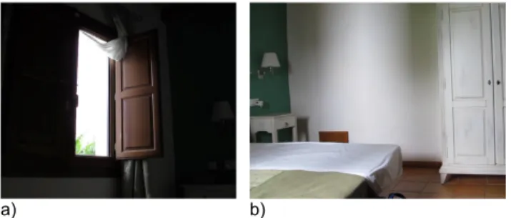
a) b)
Figure 1. a) Light enters the room via an open window. b) On the wall opposite the window, we can see a projected pattern of light and shadow. But, are the dark regions shadows? See Fig.2
one restricts the set of light rays falling on a surface, we can reveal some particular one of the images. This is what a pin-hole camera does. Only a restricted set of rays falls on the sensor, and we can observe an image if we look at a surface with light from only a pinhole falling on it. A second way to view an image when looking at a surface is to restrict the reflected rays from the surface by looking at a mirror sur-face. All rays impinge on the surface, but only those from a particular direction reflect properly into our eye and so we again see an image when viewing a surface.
There are many ways in which pictures are formed around us. The most efficient mechanisms are to use lenses or narrow apertures to focus light into a picture of what is in front. So a set of occluders (to form a pinhole camera) or a mirror surface (to capture only a subset of the reflected rays) will let us see an image as we view a surface. For those cases, an image is formed by intentionally building a particular arrangement of surfaces that will result in a cam-era.
However, similar arrangements appear naturally by acci-dental arrangements of surfaces in many places. Often the observer is not aware of the images produced by those ac-cidental cameras. Fig.1.b shows one example of a picture in which one can see a pattern of shadows and reflections projected on the walls of different scenes. Indeed, at first, one could miss-interpret some of the dark patterns on the
a)
b)
c)
d)
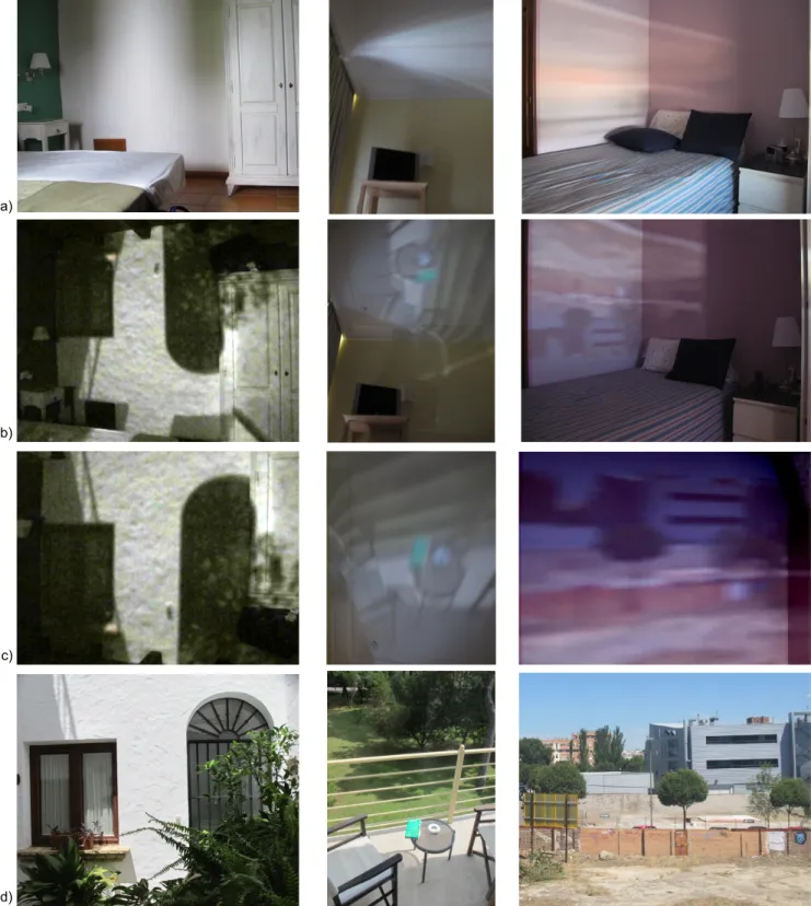
Figure 2. The top row (a) shows three different rooms illuminated by exterior light, creating shading patterns within the room. Some of these patterns may look like shadows. The images in (b), from the same viewpoints as (a), show the effect of closing the windows, leaving only a small aperture, turning the room in a camera obscura. (c) shows those images upside-down, to better reveal the formed image. (d) shows the view from the window to the outside. The shadows on (a) are in fact blurred images, not shadows. The room created an accidental camera obscura.
wall of Fig.1.b as shadows. But after close inspection, it is hard to understand which objects could be casting those shadows on the wall.
One way to reveal the origin of light patterns that appear in the room is to block the window to only allow light to en-ter only via a narrow aperture, thus transforming the room into a camera obscura. Figure2.a shows three scenes with complex patterns of lights appearing on the walls and ceil-ing. By transforming each room into a camera obscura, the images appear in focus, revealing the origin of what could be perceived at first as shadows (Fig.2.b). Fig.2.c shows the images re-oriented to allow a better interpretation of the projected image and Fig.2.d shows pictures of what is out-side of the window in each case.
Now we can see that the light patterns shown on Fig.2.a were not shadows but very blurry upside-down images of the scene outside each room. Interpreting as images the light projected by an accidental pinhole into a wall with an arbitrary geometry is not intuitive, especially when the camera obscura is created by some accidental arrangement. This, together with blurring from the window aperture, leads to most such images being interpreted as shadows.
One can bring the accidental images into focus by nar-rowing the aperture. However, there is a second way to re-veal the accidental images, described below. This second approach relaxes the constraint to have a physical pinhole aperture, but relies on multiple images and computation.
Accidental images formed by specular reflections from the eye have been studied in [11]. A Bayesian analysis of diffuse reflections over many different times has been used for imaging in astronomy applications [5].
2. Pinhole and pinspeck cameras
2.1. Pinhole camera
Let us first review the formulation of the pinhole cam-era and the description of the image that gets formed. For a more complete analysis we refer to [14]. If S(x) is the image formed by a pinhole camera, then, if we change the shape of the pinhole to have a function T (x), where T (x) = 0 means that light does not goes through and T (x) = 1 means all light passes through point x, we have I(x) = T (x) ∗ S(x).
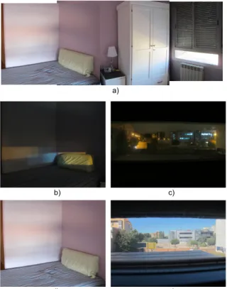
To illustrate the image formation process with a room-size example, consider the room shown in Fig.3.a. Fig.1.a shows the layout of the room that we use as a running ex-ample in this paper. In this scene, the light illuminating the room enters via a partially open window. In this particular setup, the room will act as a camera obscura with the win-dow acting as the function T (x). Fig.3shows two views of the same room under different outdoor illuminations (night time and daylight). At night, illumination sources produce an S(x) image that could be represented as a few delta
func-a)
b) c)
d) e)
Figure 3. Examples of convolutions by the aperture function. (a) Lighting within room shown together with the window opening. (b) Lighting from a night scene, and (c) the view out the window at night, showing the multiple point sources. The point sources re-veal in (b) the rectangular convolution kernel of the window aper-ture. (d) Daytime view within the room, and (e) the view out the window, which, convolved with the window aperture, yields the projected patterns in (d).
tions representing the point light sources. Therefore, the im-age I(x) looks like a few superimposed copies of the win-dow shape (and the coloring indicates which light source is responsible of each copy). Under daylight, most of the il-lumination is diffuse, and the image I(x) is the convolution of the outdoor scene with the window shape, giving a very blurry image of what is outside. We will show later how this simple model can be used to infer the shape of the window when the window is not visible in the picture. A pinhole camera is obtained when the aperture T (x) is sufficiently small as to generate a sharp image I(x).
2.2. Pinspeck camera
As discussed before, in order to get a sharp image, we need to make a small aperture T (x). This is unlikely to happen accidentally. However, another way in which rays of light that hit a surface are restricted is when there is an occluder present in the scene. An occluder blocks certain of the light rays, producing a diffuse shadow. In the cast shadow, there is more than just the silhouette of the
oc-a) b) c)
Figure 4. In this analysis we will only consider direct light rays without bounces. a) Room with a big aperture (too large to pro-duce a sharp image), b) aperture with an occluder c) difference between the two light fields, revealing just the light rays striking the small occluder.
cluder, there is also the negative image of the scene in front of the occluder. The occluder produces an anti-pinhole or pinspeckcamera. Pinspeck cameras were previously pro-posed by Adam L. Cohen [3].
Fig.4shows how an occluder produces light rays com-plementary to that of a small aperture with the size of the occluder. Fig.4.a shows the rays inside a room that enter via a window. The figure shows all the light rays that hit a point inside the room (in this drawing we assume that there are not light bounces and that all the light comes from the outside). Fig.4.b shows the light rays when there is an oc-cluder placed near the window. The difference between the two light fields is illustrated in Fig.4.c. This is:
Iwindow(x) − Ioccludedwindow(x) = Thole(x) ∗ S(x)
Fig.5shows the illumination in a room coming via win-dow when the occluder (here, a person) is absent (a) and present (b). There is a very small difference between images (c) and (d), but that difference carries information about the scene that can be seen through the window. Note that the image projected by the window with the occluder is not the negative image of the pinhole. In order to recover the image that would have been produced by a pinhole with the shape of the occluder we need to subtract two images–the image without the occluder from the image with it.
Fig.6.a shows the difference image obtained by subtract-ing Fig.5.c from Fig.5.d. In the difference image we can see an increased noise level because we are subtracting two very similar images. But we can also appreciate that a pat-tern, hidden in the images from Fig.5, is revealed. This pat-tern is a picture of what is outside the room as it would had been obtained by the light entering the room by an aperture of the size of the occluder. By making the occluder smaller we can get a sharper image, but at a cost of increased noise. Fig.7shows a second example in a different room.
2.3. Limitations
The inverse pinhole has two limitations over traditional pinhole cameras. The first is that it requires at least two images or a video from which we can extract a reference
a) b)
c) d)
Figure 5. a) Window, b) and window with an occluder, and the view of the wall opposite to the window when no occluder is present (c) and with the occluder present, (d).
a) Difference image
b) Difference upside down c) True outdoor view
Figure 6. a) Difference image (Fig.5.c minus Fig.5.d). b) Differ-ence upside-down. c) True outside scene.
background. The second limitation relates to signal to noise ratio. If the picture had no noise and unlimited precision, it would be possible to extract a perfect sharp image from the inverse pinhole. In general, to improve the signal to noise
a) Input (occluder present) b) Reference (occluder absent)
c) Difference image (b-a) d) Crop upside down e) True view Figure 7. A second example of finding a picture of what is outside a room (d) from two pictures (a) and (b). The true view (e) is shown for comparison with the recovered image (d).
ratio, traditional pinhole cameras require increasing the sen-sitivity of the light sensor or using long exposures in order to capture enough light. In inverse pinhole cameras the sig-nal to noise ratio increases when the background illumina-tion increases with respect to the amount of light blocked by the occluder. In the case of video, temporal integration can improve the signal to noise ratio.
While there are many causes of noise in images [8], if we assume just Poisson noise, proportional to the square root of the light intensity, we can calculate the SNR of the com-puted image, limited by the discrete nature of light. Let A be the area of an aperture, A =R T (x)dx. The SNR of the unoccluded photo will be proportional to√Awindow. The
signal of the difference image is proportional to Aoccluder,
while its noise is proportional to √Awindow, giving an
SNR of √Aoccluder
Awindow. Thus the SNR of the accidental image
is reduced from that of the original image by a factor of
Aoccluder
Awindow. Specifics of the sensor noise will reduce the SNR
further from that fundamental limit. Therefore, this method will work best when the light entering the room comes from a small window or a partially closed window. In such a case, the ratio between the image without the occluder and the difference image will have similar intensity magnitudes.
Despite these limitations, pinspeck cameras [3] might be used to reveal information about the scene surrounding a picture not available by other means. We will discuss appli-cations in section3.
2.4. Calibration
The main source of distortion comes from the relative orientation between the camera and the surface (or surfaces) in which the image gets projected. Fig. 8shows how the wall from Fig.3.a is corrected by finding the homography between the wall and the camera. This can be done by using single view metrology [4]. This correction is important in order to use the images to infer the window shape, in
sec-a) b)
Figure 8. a) Rectified image, and b) crop and rectified wall.
Figure 9. top row) Input sequence (a person walks inside a room moving toward and from a window not visible in the movie), bot-tom row) difference between reference image (first frame of the video) and each frame. The difference creates an approximation to a camera obscura with an aperture that moves as the occluder moves inside the room (see companion video).
tion3.3.
We have the additional difficulty of finding the reference image (the image without the occluder). If the input consists on a video, one way of deciding which frame can be used as reference is to select the frame with highest intensity (as the occluder will reduce the amount of light entering into the scene). Another possibility is to use multiple frames as reference and select the one providing more visually inter-pretable results.
3. Applications of the inverse pinhole camera
Inverse pinhole cameras occur accidentally in certain sit-uations. By studying these accidental arrangements, we can find images not directly available on the original picture. In this section we will discuss three applications.
3.1. Seeing what is outside the room
Paraphrasing Abelardo Morell [9], ”a camera obscura has been used ... to bring images from the outside into a darkened room”. As shown in section2.2, in certain condi-tions, we can use the diffuse shadows produced by occlud-ers near a window to extract a picture of what is outside of the room. Fig.9shows the result of using a video of a room in which a person is walking around. The window is not visible in the video and the person appears in view only occasionaly. But as the person walks around the room, he sometimes approaches the window, producing a change
a) b)
c) d)
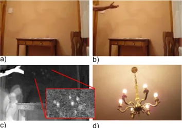
Figure 10. a) Reference image, and b) image with an occluder pro-ducing a faint shadow on the wall. There are two main occluders: a hand and a ball. The ball is already outside of the frame of the picture. c) Difference image. The shadow reveals a person throw-ing a ball. The ball acts as a pinhole camera and produces a clearer picture of the light sources. d) Picture of the lamp illuminating the scene (ground truth).
in the illumination that can be used to visualize the out-door scene. This could be used to locate where the video was recorded, or to model the illumination. To process the video from Fig.9, the first step is to identify the reference image. In this case, the reference image is selected as being the beginning of the video as it corresponds to the moment in which the user starts recording and is away from the win-dow. The reference image is obtained by averaging the first 50 frames of the video to reduce noise. To select the ref-erence image (corresponding to the moment in which the window is unoccluded) we can also select the frames with the highest intensity, or the frame that when subtracted from the others produces the smallest number of negative values. Fig.9.a shows the input video (see supplementary ma-terials for the full video) and Fig.9.b shows the difference between the background image and the input video. The first frame is only noise, but as the person moves we can see how the wall reveals a picture. As the person moves, the occluder produces a pinhole camera with the pinhole in different locations. This produces a translation on the pic-ture that appears on the wall. These translated copies of the image contain disparity information and could be used to recover the 3D structure if the noise is low enough.
3.2. Seeing light sources
In indoor settings, most of the illumination is dominated by direct lighting. Due to the large ratio between direct and indirect illumination when there are direct light sources, shadows can only be used to recover the light sources. If the signal to noise ratio were sufficiently large, it could be
pos-a) b) c) d)
Figure 11. a) Reference image, and b) image with an occluder pro-ducing a faint shadow on the wall. The occluder is produced by the hand of a person that is about to open the door to enter the room c) Difference image. d) Picture of the light sources in the corridor, showing the lights revealed in (c).
sible to get a picture of the rest of the scene. Figures 10 and11 show two examples. In Fig.10 a ball produces a shadow that can be used to extract a picture of the lamp in the ceiling. In Fig.11, a person is entering a room. Their holding the door handle produces a shadow inside the room that can be used to recover the light sources in the corridor outside the room.
3.3. Seeing the shape of the window
Fig.12shows a series of pictures taken in two different rooms with windows closed by different amounts and with different shapes. As the window closes, the pattern of illu-mination inside the room changes. Note that when there is diffuse illumination coming from the outside, the window shape is not clearly visible on the wall. This is clearly illus-trated on Fig.3. Fig.3shows that when there are point light sources outside, the window shape appears clearly projected onto the wall. However, with more general outdoor scenes, the window shape is not visible directly. However the win-dow shape has a strong influence on the blur and gradient statistics of the pattern projected onto the wall.
As discussed in section2.1, the pattern of intensities on the wall corresponds to a convolution between the window shape and the sharp image that would be generated if the window was a perfect pinhole. Therefore, the shape of the window modifies the statistics of the intensities seeing on the wall just as a blur kernel changes the statistics of a sharp image. This motivates using algorithms from image deblur-ring to infer the shape of the window. The shape of the window can be estimated similarly to how the blur kernel produced due to motion blur is identified in the image de-blurring problem [6].
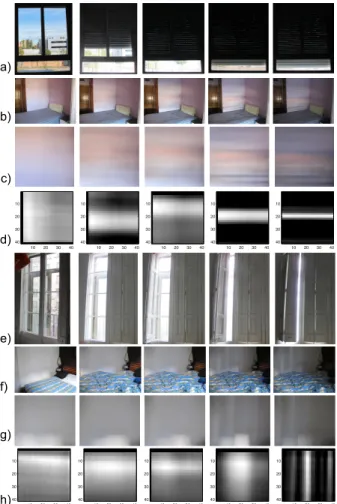
Fig. 12 shows the estimated window shapes using the algorithm from [6]. The input to the algorithm are the im-ages from Fig. 12.b and e and the output are the window shapes shown in Fig.12.c and f. The method shows how the kernel gets narrower as the window is closed and it also correctly finds the orientation of the window. It fails only
10 20 30 40 10 20 30 40 10 20 30 40 10 20 30 40 10 20 30 40 10 20 30 40 10 20 30 40 10 20 30 40 10 20 30 40 10 20 30 40 a) b) c) 10 20 30 40 10 20 30 40 10 20 30 40 10 20 30 40 10 20 30 40 10 20 30 40 10 20 30 40 10 20 30 40 10 20 30 40 10 20 30 40 d) e) f) g) h)
Figure 12. a,e) Window (ground truth), b,f) picture of the room, c,g) warped and cropped wall region (input to the estimation), and d,h) estimated window shape (the estimated shape is quite robust to the size of the estimated kernel size). Note that the kernel esti-mation algorithm infers the qualitative size and shape of the win-dow apertures in most cases.
when the window is very open as the pattern of intensities is too blurry, providing very little information.
Finding the light sources, window shape and the scene outside a picture could be used in computer graphics to pro-vide a better model of the light rays in the scene to render synthetic objects that will be inserted inside the picture.
3.4. Seeing the illumination map in an outdoor scene
Accidental cameras happen also in outdoor environ-ments. For instance, let’s consider a movie with a person walking in the street. When the person is walking under direct illumination from the sun, the person casts a well de-fined shadow which is a negative picture of the sun distorted by the shape of the person. When the person walks into a shadowed region by a building, the shadow seems to dis-appear (Fig.13.a). However, a faint shadow is still present as the person will block some of the light rays. The shadow
a) Input (person walking) b) Background (median)
c) Difference (negative shadow)
Figure 13. A person walking in the street projects a complex shadow containing information about the full illumination map outside the picture frame.
will not be a sharp shadow on one side of the person, instead the shadow will be all around the person on the floor and on the building facades near the person. This is illustrated in Fig.13which shows one frame of a sequence with a person walking. Fig.13.b shows the background image (computed as the median of all the frames in the video), and Fig.13.c shows the difference (b)-(a), which is the negative of the shadow.
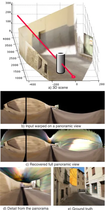
If we knew the 3D geometry of the scene and the lo-cation of the occluder, then we could infer where the light rays that contribute to the shadow come from and we could reconstruct the scene around the person and outside of the picture frame. In order to recover the 3D geometry we use single view metrology. We use LabelMe 3D which allows recovering metric 3D from object annotations [13]. This shown in Fig.14.a. Fig.14.b shows the panoramic image reconstructed only from the information directly available from the input Fig.14.a. In black are shown the pixels not directly visible in the input picture. Fig. 14.c shows the recovered panorama using the shadow of the person and Fig.14.d shows a crop of the panorama corresponding to the central region. The yellow region visible in Fig.13.c is in fact a building with a yellow facade as shown in the ground truth picture Fig. 14.e which shows the full scene. Note that the shadow projected on the wall on the left side of the picture provides information about the right side of the scene not visible inside the picture.
a) 3D scene
b) Input warped on a panoramic view
c) Recovered full panoramic view
d) Detail from the panorama e) Ground truth
Figure 14. This figure illustrates how to use the shadow projected by a person (from Fig.13) to recover a panoramic view of the scene outside the picture frame.
4. Conclusion
We have described and shown “accidental” images that are sometimes found in scenes. These images can either be direct, or processed from several images to exploit “inverse pinholes”. These images (a) explain illumination variations that would otherwise be incorrectly attributed to shadows, can reveal (b) the lighting conditions outside the interior scene, or (c) the view outside a room, or (d) the shape of
the light aperture into the room, and (e) the illumination map in an outdoor scene. While these are inherently low signal-to-noise images, or are blurry, understanding them is required for a complete understanding of the photometry of many images. Accidental images can reveal parts of the scene that were not inside the photograph or video and can have applications in forensics [12].
Acknowledgments
Funding for this work was provided by NSF Career award 0747120 to A.T, and NSF CGV 1111415 and NSF CGV 0964004 to W.T.F.
References
[1] E. H. Adelson and J. Y. Wang. Single lens stereo with a plenoptic camera. IEEE Trans. on Pattern Analysis and Ma-chine Intelligence, 14(2):99–106, 1992.1
[2] S. Baker and S. Nayar. A theory of single-viewpoint cata-dioptric image formation. International Journal on Com-puter Vision, 35(2):175–196, 1999.1
[3] A. L. Cohen. Anti-pinhole imaging. Optical Acta, 29(1):63– 67, 1982.4,5
[4] A. Criminisi, I. Reid, and A. Zisserman. Single view metrol-ogy. International Journal on Computer Vision, 40(2):123– 148, 2000.5
[5] S. W. Hasinoff, A. Levin, P. R. Goode, and W. T. Freeman. Diffuse reflectance imaging with astronomical applications. In IEEE International Conf. on Computer Vision, 2011.3
[6] D. Krishnan, T. Tay, and R. Fergus. Blind deconvolution using a normalized sparsity measure. volume IEEE Conf. on Computer Vision and Pattern Recognition, 2011.6
[7] A. Levin, R. Fergus, F. Durand, and W. T. Freeman. Image and depth from a conventional camera with a coded aperture. ACM Trans. On Graphics (Proc. SIGGRAPH 2007), 2007.1
[8] C. Liu, R. Szeliski, S. B. Kang, C. L. Zitnick, and W. T. Freeman. Automatic estimation and removal of noise from a single image. IEEE Trans. on Pattern Analysis and Machine Intelligence, 30(2):299–314, 2008.5
[9] A. Morell. A camera in a room, 1995.5
[10] S. Nayar, G. Krishnan, M. Grossberg, and R. Raskar. Fast separation of direct and global components of a scene us-ing high frequency illumination. ACM Trans. On Graphics (Proc. SIGGRAPH 2006), 2006.1
[11] K. Nishino and S. K. Nayar. Corneal Imaging System: En-vironment from Eyes. International Journal on Computer Vision, Oct 2006.3
[12] J. O’Brien and H. Farid. Exposing photo manipulation with inconsistent reflections. ACM Transactions on Graphics, 31(1):4:1–11, 2012.8
[13] B. C. Russell and A. Torralba. Building a database of 3d scenes from user annotations. In IEEE Conf. on Computer Vision and Pattern Recognition, pages 2711–2718, 2009.7
[14] A. Zomet and S. K. Nayar. Lensless Imaging with a Con-trollable Aperture. In IEEE Conf. on Computer Vision and Pattern Recognition, Jun 2006.3