ANALYSIS OF DESIGN STRATEGIES FOR MITIGATING THE CONSEQUENCES OF LITHIUM FIRE WITHIN CONTAINMENT OF CONTROLLED THERMONUCLEAR
REACTORS by
D. A. Dube and M. S. Kazimi
DEPARTMENT OF NUCLEAR ENGINEERING MASSACHUSETTS INSTITUTE OF TECHNOLOGY
Cambridge, Massachusetts 02139
July 1978
ANALYSIS OF DESIGN STRATEGIES FOR MITIGATING THE CONSEQUENCES OF LITHIUM FIRE WITHIN CONTAINMENT OF CONTROLLED THERMONUCLEAR
REACTORS by
D. A. Dube and M. S. Kazimi
Report Issued Under Contract EY-76-02-2431
ABSTRACT
A lithium combustion model (LITFIRE) was developed to
describe the physical and chemical processes which occur during
a hypothetical lithium spill and fire. The model was used to
study the effectiveness of various design strategies for miti-gating the consequences of lithium fire, using the UWMAK-III
features as a reference design. Calculations show that without
any special fire protection measures, the containment may reach
pressures of up to 32 psig when one coolant loop is spilled
inside the reactor building. Temperatures as high as 2000 *F would also be experienced by some of the containment strucLu.es. These consequences were found to diminish greatly by the
incor-poration of a number of design strategies including initially
subatmospheric containment pressures, enhanced structural
sur-face heat removal capability, initially low oxygen
concentra-tions, and active post-accident cooling of the containment gas.
The EBTR modular design was found to limit the consequences of
a lithium spill, and hence offers a potential safety advantage.
Calculations of the maximum flame temperature resulting from
lithium fire indicate that none of the radioactive first wall materials under consideration would vaporize, and only a few
PUBLICATIONS UNDER CONTRACT EY-76-02-2431
1. R. Sawdye, J. A. Sefcik and M. S. Kazimi, "Reliability Requirements for Admissible Radiological Hazards from Fusion Reactors," Trans. Am. Nucl. Soc. 27, 65-66, November 1977.
2. M. S. Kazimi et al., "Aspects of Environmental and
Safety Analysis of Fusion Reactors," MITNE-212, Dept. Nucl. Eng., M.I.T., October 1977.
3. D. Dube, M. S. Kazimi and L. M. Lidsky, "Thermal Response of Fusion Reactor Containment to Lithium Fire," Paper presented at Third Top. Meeting on Fusion Reactor Tech-nology, Santa Fe, N.M., May 1978.
4. R. W. Sawdye and M. S. Kazimi, "Application of Probabi-listic Consequence Analysis to the Assessment of Potential Radiological Hazards of Fusion Reactors," MITNE-220,
Dept. Nucl. Eng., M.I.T., July 1978.
5. D. A. Dube and M. S. Kazimi, "Analysis of Design Strate-gies for Mitigating the Consequences of Lithium Fire within Containment of Controlled Thermonuclear Reactors," MITNE-219, Dept. Nucl. Eng., M.I.T., July 1978.
ACKNOWLEDGEMENTS
This report is based on a thesis submitted by the first author to M.I.T. in fullfillment of the requirements for the degree of Master of Science in Nuclear Engineering.
The authors would like to thank Lenny Andexler for his help with graphing, Robert Green for his help in getting the
computer code SPOOL-FIRE working and Gail Jacobson for her patience and effort in getting this report typed.
TABLE OF CONTENTS Page Abstract 1 Acknowledgements 3 List of Figures 7 List of Tables 9 Chapter I. Introduction 10
Chapter II. Combustion of Liquid Lithium 16 2.1 Thermochemical Considerations 16 2.2 Lithium-Air Adiabatic Flame Temperature 19
2.3 Experimental Observations 29
Chapter III. The LITFIRE Model for Lithium Combustion
in CTR Containments 32
3.1 Introduction 32
3.2 Major Assumptions of the Combustion Model 35
3.3 Heat Transfer Mechanisms 39
3.3.1 Heat Conduction from the Combustion
Zone to the Containment Atmosphere 39 3.3.2 Heat Convection from the Combustion
Zone to the Containment Atmosphere 41 3.3.3 Thermal Radiation from the
Combustion Zone 46
3.3.4 Heats of Combustion for Lithium
Reactions 50
3.3.5 Sensible Heat Addition to the Reaction Products and Reactants
in the Combustion Zone 51
3.3.6 Combustion Zone Heat Balance 53
3.4.1 Mass Transfer of Oxygen, Nitrogen, and Water Vapor
3.4.2 Lithium Mass Transport to the Combustion Zone
3.4.3 Lithium-Nitrogen Reaction
3.5 Containment Thermal Model 3.5.1 Containment Pressure 3.5.2 Containment Leakage
3.5.3 Heat Conduction through the Contain-ment Structures to the Ambient
3.5.4 Containment Spray Model
3.5.5 Modeling of Emergency Cooling of the Containment Atmosphere
3.5.6 Modeling of Emergency Cooling of the Steel Floor Liner
3.5.7 Modeling of Containment Atmosphere Ventilation and Inert Gas Flooding 3.6 The Numerical Scheme
Chapter IV. Design Strategies for Mitigating the Consequences of Lithium Fires
4.1 Introduction
4.2 Application of LITFIRE to Lithium Fires in UWMAK-III
4.2.1 Description of UWMAK-III Containment 4.2.2 Discussion of Important Base Case
Parameters
4.2.3 Results of Sensitivity Study
4.3 Inherent Safety Features of Fusion Reactor Containment and Cooling Systems
4.3.1 Multiplicity of Parallel Cooling Systems
4.3.2 Modularization of Fusion Reactor into Individual Compartments Page 53 57 59 60 60 60 61 63 66 67 68 70
72
72
73
73
73
79
86
86
89
4.3.3 Reduction of Oxygen Concentration
in the UWMAK-III Containment 91 4.3.4 Reduction of Initial Containment
Gas Pressure 94
4.3.5 Introduction of Structures with High Heat Capacities and Thermal
Conduc-tivities 97
4.4 Engineered Safety Features of Fusion Reactor
Containments 99
4.4.1 Emergency Cooling of Containment
Atmosphere 99
4.4.2 Ventilation of Containment Atmosphere 100 4.4.3 Emergency Cooling of Steel Floor Liner 102 4.4.4 Other Possible Design Features 106 4.4.4.1 Use of Catch Pans 106 4.4.4.2 Lithium Fire Extinguishment
with Chemicals 107
4.4.4.3 Inert Gas Flooding of
Contain-ment 108
4.4.5 Combined Effect of Safety Features 108
Chapter V. Conclusions and Recomendations 113
5.1 Conclusions 113
5.2 Recommendations for Future Study 115
References 117
Appendix A: Complete Listing of LITFIRE 122
Appendix B: Sample Input to LITFIRE 153 Appendix C: Sample Output of LITFIRE 155
LIST OF FIGURES
No. Page
2.1 Equilibrium Temperature vs. Lithium to Air Mole
Ratio for Two Li Release Temperatures 25 2.2 Equilibrium Temperature vs. Lithium to Nitrogen
Mole Ratio for Two Li Release Temperatures 26 3.1 Flow Diagram of the LITFIRE Program 34 3.2 Heat Flow Diagram for Lithium Pool Combustion in
CTR Containment 36
3.3 Mass Flow Diagram for Lithium Pool Combustion in
CTR Containment 37
3.4 Equivalent Circuit for Radiation Heat Exchange Between Lithium Pool Surface, Cell Gas, Combustion
Zone, and Containment Walls 47
3.5 Basic Containment Structural Model 62 4.1 Cross Section of UWMAK-III Primary Containment
Building 74
4.2 Best Estimate of the Containment Thermal Response
to Lithium Fire in UWMAK-III 87
4.3 Best Estimate of the Containment Gas Pressure to
Lithium Fire in UWMAK-III 88
4.4 Modularization of Fusion Reactor as Illustrated
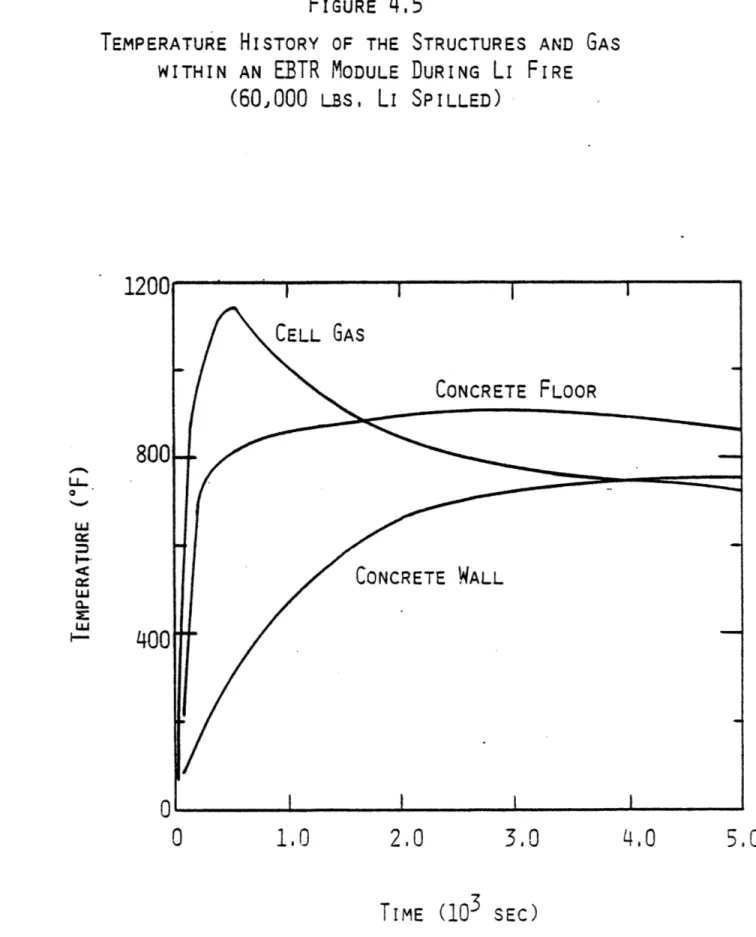
in the ELMO Bumpy Torus Reactor 90 4.5 Temperature History of the Structures and Gas
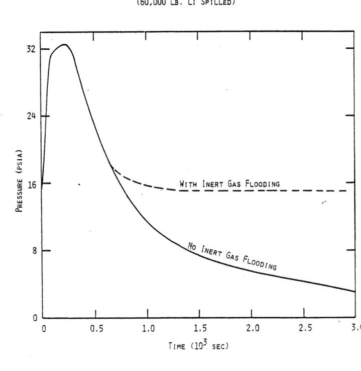
within an EBTR Module During Li Fire 92 4.6 Pressure History of the Air within an EBTR Module
During Li Fire 93
4.7 Maximum UWMAK-III Containment Gas Overpressure During Li Fire as Function of Initial 02
Con-centration 95
4.8 Maximum UWMAK-III Containment Gas Overpressure
No. Pag 4.9 Maximum UWMAK-III Containment Gas Overpressure
During Li Fire as Function of Emergency Space
Cooling Rate 101
4.10 Maximum UWMAK-III Containment Gas Overpressure During Li Fire as Function of Emergency
Ventila-tion Rate 103
4.11 Maximum UWMAK-III Containment Gas Overpressure During Li Fire as Function of Emergency Steel
Floor Liner Cooling Rate 105
4.12 Temperature History of the UWMAK-III Structures During Li Fire and Employing Readily Available
Design Strategies 111
4.13 Pressure History of the UWMAK-III Containment Gas During Li Fire and Employing Readily
LIST OF TABLES
No. Page
1.1 Energy and Heat Sources and Sinks in UWMAK-I and III 12 2.1 Heats of Formation and Changes in Gibbs Free Energy
for Li3N(c) and Li20(c) 18
2.2 Thermodynamic Results from Sample Calculations for
Determining Adiabatic Flame Temperature 22
2.3 Melting and Boiling Points of Some Metals Being
Considered as First Wall or Structural Materials 28 3.1 Values of D(mass diffusivity) and a (thermal
dif-fusivity) for Oxygen and Nitrogen in Air as
Functions of Temperature 56
3.2 Thermophysical Data Used in Containment Structures
Heat Transport Calculations 64
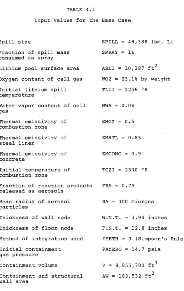
4.1 Input Values for the Base Case 76
4.2 Compilation of Sensitivity Study 81
4.3 Summary of Effectiveness of Designed Safety
I. INTRODUCTION
Development of controlled thermonuclear reactors (CTR)
designs must include evaluation, elimination and/or
minimiza-tion of the mechanisms for the release of large amounts of
energy, and subsequent release of radioactivity to the
environ-ment. One such mechanism is the chemical reaction of liquid
lithium with air or other gases resulting from a rupture of
the lithium coolant piping or equipment. A possible
conse-quence of liquid lithium fires is the overpressurization and
rupture of the reactor containment. In addition, the high
temperatures and pressures accompanying lithium fires can
po-tentially provide the means for mobilizing a significant portion
of the radioactive inventory, which includes the activated first
wall and structures, and tritium.
Many fusion reactor designs use liquid lithium as coolant
and breeding material because of its low melting point, high
boiling point, low vapor pressure, low density, high heat
capacity, high thermal conductivity, and low viscosity.
Lith-ium requires less pumping power when flowing across magnetic field lines than most other liquid metals, and lithium is not
activated to long-lived gamma emitting isotopes by neutron capture.1
However, liquid lithium reacts strongly in air, libera-ting about 3.7 times more energy on a weight basis than liquid
sodium (which is itself being considered for use in the
be reached in some designs where a refractory metal or alloy
is employed as structural material.2
Should a large amount of liquid lithium become exposed
to air within the reactor containment building, there is a
potential for release of substantial amounts of energy.
(Exam-ples of the energy sources and sinks in Tokamak reactors are
given in Table 1.1). Furthermore, lithium may interact with
the concrete floors or structures, releasing still more energy.
The designer of the reactor containment must take such
hypo-thetical accidents from lithium spills into consideration.
Examples of the CTR containment designs so far proposed
are those of UWMAK-I, UWMAK-III, and EBTR reactors.
The UWMAK-I CTR design includes a double containment.3
The inner primary containment is evacuated to a pressure of
1 Torr. It is designed to withstand an overpressure of 10 psig caused by liquid helium coolant leakage and vaporization.
It would have a 0.5 in. steel liner to prevent lithium-concrete
reactions should a spill occur. The UWMAK-III design utilizes
a single containment of roughly one and one-half the free
volume of UWMAK-I (8.85 X 106 ft.3 compared to 5.65 X 106 ft. 3 The containment atmosphere is an inert gas and the structure
is lined with 0.25 in. steel plate. The design overpressure
is 15 psig. The ELMO Bumby Torus Reactor reference design
(EBTR) has a much larger aspect ratio than the Tokamak-type fusion reactor designs and hence employs a primary contain-ment similar to those used for large underground particle
TABLE 1.1
-Energy and Heat Sources and Sinks in UWMAK-I and III
UWMAK-I UWMAK-III
Superconducting
magnets
Kinetic energy
of plasma
Thermal energy of
liquid lithium
Li-air reactions
Li-concrete
reactions
Thermal energy of
gaseous helium*
350
X
109
J
3 X 10
9 J
32.5 X 10⁹ J/%
280-731 X 109 J/%
1200 X 109 J/%
Li
Li
Li
.34
X 10J9 J
(from shield)
Approximately same Approximately same 15.8 X 10⁹ J/% Li 65-170 X 109 J/% Li 278 X 109 J/% Li 27 X 109 J (inner blanket) SINKSLiquid helium*
Heat capacity of air* Heat conductionthrough the concrete containment 84 X 109 J 61.1 X 10⁶ J/*C .8-1.0 X 100 W (T-T )
*d
amb
same
95.7 X 10⁶ J/*C 1.2 X 10⁴ W (T-T )g
amb
Heat capacity of containment structures. 7.3 X 10 J/*C9.8
X 10
J/*C
* Ambient is taken as zero-base in calculation of thermal energy SOURCES
accelerators. EBTR is modularized into as many as 48 units, with each section containing 3.5 X 10 4 ft.3 of free volume. No provision has yet been made for partial evacuation of the
containment.
Air could be introduced into an otherwise evacuated
envi-ronment by a breach of the primary containment by a missle or
seismic activity. In these cases it would be impossible to
prevent leakage of air into the containment and the main
con-cern would lie in minimizing lithium leakage and peak flame
temperatures. Also, under some circumstances, it may be
preferable to operate with an atmospheric environment. If an
inert containment atmosphere were properly maintained, and the
steel liner were effective in separating the lithium from
concrete, a lithium spill by itself would pose little danger to
the containment integrity.
Because the lithium would be contained in a multiplicity
of parallel systems (12 for UWMAK-I, 18 for UWMAK-III, and up to 48 for EBTR), rupture of a single lithium system could not
release more than a small fraction of the total lithium
inven-tory. However, in absolute terms, this could amount to a large
spill nonetheless (312,000 lbs. in UWMAK-I, 48,400 lbs. in
UWMAK-III, and approximately 62,500 lbs. in EBTR). A spill of this size might cause large thermal stresses in the steel
liner possibly causing it to buckle and allowing lithium to
contact the concrete structure beneath. Lithium reacts readily with concrete giving off hydrogen, oxygen, carbon dioxide, and
water vapor. Release of these gases might further displace
the liner, allowing still more leakage.
If a lithium spill occurs, the lithium's tritium inventory
would be released into the containment atmosphere creating a
radiation hazard. The lithium also contains activated blanket
wall erosion and corrosion products. If a fire occurs it is
possible that some products be volatilized and released into
the containment atmosphere. The fire might also supply the
energy needed to disrupt the first wall and other activated
reactor structures. This radiological hazard combined with the
very large potential energy release necessitates that we develop
a detailed understanding of lithium fires and means of mitiga-ting their consequences.
In this work, a lithium pool combustion model is developed to account for the reaction of liquid lithium with both oxygen and nitrogen. The model includes the effects from moisture in
the atmosphere and subsequent hydrogen gas generation resulting from lithium-water reaction. Radiative and convective heat
transfer from the combustion zone to the containment walls and to the cell gases are considered. Convective mass transport of oxygen and nitrogen, and diffusive lithium vapor transport
to the zone are also included. The model also considers heat loss from the containment to the ambient, and heat absorption by internal structures.
The design strategies analyzed for mitigating the conse-quences of lithium fires include:
1) emergency space cooling of the containment atmosphere;
2) inert gas flooding of the containment;
3) containment ventilation;
4) surface cooling of the lihtium pool;
5) modularization of the reactor as employed in the EBTR
design;
6) reduction of the initial concentration of oxygen within
the containment;
7) reduction of the initial containment gas pressure;
8) employing structural materials with high heat
capaci-ties and thermal conductivicapaci-ties;
9) employing a multiplicity of parallel cooling systems;
10)
the use of "catch pans," dump tanks, and chemical
II. COMBUSTION OF LIQUID LITHIUM
2.1 Thermochemical Considerations
The major safety concern when using liquid lithium as a
fusion reactor coolant is its exothermic reaction with air as
well as with the concrete containment should a lithium spill
occur. Unlike sodium, liquid lithium also reacts exothermically
with nitrogen gas at elevated temperatures. The reactions in
air of greatest interest are:1
AH 9 8kcal/mole AG9 kcal/mole
A98
298
2 Li(c) + 402 + Li 20 (c) -142.75 -133.95
2 Li(c) + 02 + Li202(c) -151.9 -133.1
Li(c)
+H
2 +02
+LiOH(c)
-166.58
-105.68
3 Li(c) + N2 (g) Li3N(c) - 47.5 -37.3where AH* is the change in enthalpy between the products and
reactants (also known as the heat of formation), and AG0 is
the change in Gibbs free energy. Negative values of AH*
indi-cate exothermic reactions. The zero superscript refers to
enthalpy changes with respect to the standard state (1
atmo-sphere of pressure).
The heat of formation AH* is a function of reaction
temper-ature as well. Most thermodynamic data give values of AH* at
room temperature (298.15*K to be precise). However, one would
accurately reflect the energy release for reactions which occur
at temperatures other than 209.150K. Table 2.1 gives the heats
of formation and the change in Gibbs free energy of Li2O(c) and
Li3N(c) for various temperatures.5
In any chemical situation the forward reaction may be ex-pressed as
A + B - C (2.1)
while the reverse reaction may be expressed as
C + A + B (2.2)
At chemical equilibrium, one obtains the standard form
A + Bd 4C (2.3)
Large negative values of AG0 indicate, in general, that the
T
forward reaction goes nearly to completion, while large
posi-tive values of AG0 indicate that the reverse reaction is
pre-T
ferred thermodynamically.
One can represent a chemical transformation for ideal
gases, for example, by the equation
aA + bB a cC + dD, (2.4)
where the lower-case letters represent the number of moles
and the upper-case letters represent the reactants and Products. One can then represent AG* mathematically by
T
AGO = -RT ln K
TABLE 2.1
Heats of Formation and Changes in Gibbs Free Energy for
Li3N(c) and Li2O(c)*
AHO (kcal/mole) AGO (kcal/mole)
T
T
TEMP (*K) Li3N(c) Li2O(c) Li3N(c) Li2O(c) 298 -47.2 -143.1 -36.8 -134..3 400 -47.4 -143.3 -33.3 -131.3 500 -49.8 -144.9 -29.5 -128.2 600 -49.9 -145.0 -25.4 -124.8 700 -49.7 -145.0 -21.3 -121.5 800 -49.2 -144.9 -17.3 -118.1 900 -48.7 -144.7 -13.3 -114.8 1000 -48.0 -144.5 - 9.5 -111.5 1100 -47.2 -144.1 - 5.7 -108.2 1500 -43.8 -142.5 + 8.9 - 95.4*Janaf Thermochemical Tables
where
K
[C]
[D]
(2.6)
[A]'
[B]b
and is called the thermodynamic equilibrium constant. R is the
universal gas constant (1.987 cal/gm-mole *K) and T is the
absolute temperature. The values in the brackets refer to the
corresponding mole concentrations of the products, while the
lower-case letters are exponents in the above expression for K.
Hence, large negative values of AG* indicate relatively high
T
concentrations of the products C and D, and the forward
reac-tion more nearly goes to complereac-tion at chemical equilibrium.
Gibbs free energy can be represented more accurately by
G* = H* - TS* (2.7)
while the change in Gibbs free energy is represented by
AG* = AH* - TAS* (2.8)
T
for infinitesimal changes under isothermal conditions. AS*
represents the change in entropy for the reaction in the
stan-dard state. A more complete discussion of chemical
thermo-dynamics for reactions involving liquids, solids, and changes
in state is treated by Klotz6 for example.
2.2
Lithium-Air Adiabatic Flame Temperature
Of primary concern in lithium fires is the peak flame
tem-perature which can be achieved. To a large extent, this will
determine whether many radioactive species become airborne
by vaporization or aerosol formation in fusion reactor
acci-dents.
The standard procedure is to assume a number o-f
con-straints on the lithium-air reaction to establish peak flame
temperatures
-
in essence, 1) reactant stoichiometry, 2)
chemical equilibrium between the product species, and 3)
over-all adiabatic conditions. In reality, one can expect
signi-ficantly lower temperatures to be achieved because of
radia-tive transfer and constraints on the reaction rates. These
further constraints will be considered later. However, the
present analysis does provide an absolute upper bound for the
flame temperature, albeit a very conservative one.
The procedure used in determining chemical equilibrium is
an established one and is treated especially well by Zeggeren
and Storrey.
Briefly, the procedure involves the minimization
of Gibbs free energy for all the reactants, products, and their
concentrations under consideration. It is assumed that all of
the energy released from the chemical reactions is used in
heating the product species to the equilibrium temperature.
Gordon and
McBride
have developed a special computer
pro-gram, CEC 71, for calculating thermochemical values in rocket
engines.
This code, developed for NASA, and available at MIT
under the name TRAN72, includes other options used in studying
jet propulsion, but are not considered here.
Thermochemical
and physical data for some 62 reactants and 421 reaction
spe-cies in liquid, solid, and gaseous states are included. The
input requires specifying the reactant concentrations (by
weight or moles) and the initial enthalpies (or temperatures)
of these reactants. The resulting output provides information
on the product concentrations, equilibrium temperature,
den-sity, effective molecular weight, and so forth. Of greatest interest is of course the equilibrium temperature, but the
product concentrations further provide information on which
reactions are dominant.
Using this computer code, a number of cases were run
under similar conditions except for reactant concentrations
to note the contribution of the various reactants to the total
energy release.
In case 1, it is assumed that a leakage of 16% of the
total lithium inventory of UWMAK-III (about three coolant
loops) has resulted and reacted with the volume of air within
the containment. The reaction is assumed to occur with air
at room temperature, 1 atmosphere of pressure, and 50%
rela-tive humidity. Case 2 was similar to case 1 but dry air was
used instead. Case 3 considered only lithium, oxygen, and
nitrogen as reactants. In case 4, only nitrogen and lithium
were used as reactants. Table 2.2 summarizes the assumptions
and the results of all four cases.
It is significant to note that the equilibrium temperature
reached is quite insensitive to those reactants considered
other than nitrogen and oxygen. Further analysis shows that in the presence of small concentrations of oxygen, the
percen-TABLE 2.2
Thermodynamic Results from Sample Calculations for Determining Adiabatic Flame Temperature.
INPUT
Case 1
Case 2
Case 3
Case 4
Reactants Considered Li(l)and Mole Fractions
N 2 H20 Ar CO 2 H 2
.45800
Similar
.41000but
.11000 no H20.01862
.00495
.00026
.00005
OUTPUT Equilibrium *K Temperature Energy Released (kcal/gm Li reacting) Products resulting and mole fractions(greater than
1
X
10-5)
2498
10.4
Ar Co Co 2 Li LiO LiOH Li2 (g) Li2O(1).00722
.00010
2498 10.4 2500 10.41094
2.3
.00722
.00010
.00028 .00028 .08670 .00767 .00014 .00006 .11990 .08670 .00767 .00014 .00006 .11990 .08767 .00151 .00778 -.00006.12012
.00002
Li
20
.16524
.16524
.16703
Li
20
2.00156
.00156
.00158
NO N 2 0 02 Li3N(s) .00446.00446
.00452 .59579 .59579 .60024 .00131 .00131 .00133.00957
.00957
.88433.00968
.11414.468
.419
.113
.27 .73tage of nitrogen which underwent reaction is very small.
Several reasons can be given to account for this observation.
For one, the lithium-oxygen reaction is significantly
more exothermic than the lithium-nitrogen reaction. Hence,
one would assume that in establishing equilibrium, reaction
with oxygen would be preferred over nitrogen. In addition,
the change in Gibbs free energy for the reaction is greater
for oxygen than nitrogen, indicating that the forward reaction
with oxygen is carried to greater completion than with
nitro-gen. Although the heat of formation of Li3N is fairly constant
over a wide range of temperatures, the value of AGO increases
significantly with temperature. At 298 K, the value of AGO
is -36.8 kcal/mole, while it increases to -17.3 kcal/mole at
800 *K and still higher to +8.9 kcal/mole at 1500 *K. This would indicate that the forward reaction of lithium-nitrogen
at elevated temperatures is very slow. Note also that the
melting point of Li3N is 1123 *K so that Table 2.1 should not be
used above this temperature.
Close examination of lithium-oxygen reaction, on the other
hand, shows that for Li2O(c), AG* = -134.3 kcal/mole at 298 *K,
-118.1 kcal/mole at 800 *K*, and -95.4 kcal/mole at 1500 *K. Hence, the forward lithium-oxygen reaction is still very
impor-tant at elevated temperatures. Indeed, these observations
imply that liquid lithium-nitrogen reaction would be important
at relatively low combustion temperatures of 400-500 *K, and unimportant in the regime of temperatures above 1000 *K.
However, the fact that lithium-nitrogen reactions are
exother-mic at all temperatures still means that nitrogen would be
insufficient for the extinguishment of lithium fires.
Several other cases were investigated to determine the
effects of the relative mole fraction of air and
Li-to-nitrogen on the final equilibrium temperature. Figures 2.1
and 2.2 illustrate this as well as the effect of the lithium
release temperature on the final temperature. Calculations
were made for lithium release temperatures of 1173 *K, 1000
*K, 800 *K, and 600 *K, but only the curves for 1173 *K and 600 *K are plotted. The peak flame temperature obtained for lithium fires in air is 2502 *K, while the peak flame
tempera-ture for Li in N2 is 1315 *K. The value of 2502 *K compares
quite closely with the value of 2400 *K obtained by Okrent
et al.9 It was also found that for environments of low oxygen
concentration (4 and 8%), the peak flame temperatures were
reduced significantly to 1580 *K and 1800 *K respectively at
Li release temperatures of 1173 *K. Moreover, it was found
that except for environments with low oxygen concentrations
(<5% volume), lithium-nitrogen reactions were unimportant at chemical equilibrium.
This leads to the following conclusions:
1) The lithium-oxygen reactions predominate in atmos-pheric environments, while the lithium-nitrogen reactions are
relatively unimportant except at very low concentrations of
EQUILIBRIUM
TEMPERATURE VS. LITHIUM To AIR
hOLE RATIO
FORTwo LI
RELEASE
TEMPERATURES-0.4
0.8
10
1.2
MOLE LITHIUM
MOLE AIR
30
20
%
Li INVENTORY(UWMAK-III)
2600
2200
1800
1400
0 w H w w -j D C LU1000
Ln0
0
1.6
a
a
I'
0
0.4
0.8
0
.10
MQLE-LITTHIUM1.2
MOLE NITROGEN 1.620
Z
Li
INVENTORY(UWMAK-III)
1400
1200
0 w cc I-4 cc w a-S w F-S D cc cti -J a LU1000
800
600
400
30
I2) In an N2 environment, lithium reacts exothermically
with the nitrogen gas, although the forward reaction is
con-strained by thermodynamic considerations, resulting in peak
flame temperatures which are significantly lower than those
found in an air environment.
The first conclusion suggests that it is possible to
model lithium-oxygen reactions in an atmospheric environment
in much the same way as was done in several studies to
sodium fires in LMFBRs.1 0-1 3 This would make it possible to
predict the temperatupressure history of containment
re-sulting from lithium fires. At lower oxygen concentrations,
the model can be modified to account for lithium reactions
with nitrogen.
Of considerable interest is the possible vaporization of reactor materials in the event of a lithium fire. Table 2.3
gives the melting points and some vaporization points for
those metals considered likely to be used as first wall or as
structural material. It can be seen that even at temperatures
of 2502 *K (which is the highest peak flame temperature
calcu-lated from this investigation), none of the materials would
vaporize, although several would melt. Further study would
have to be made to determine if aerosol formation is
signifi-cant at these temperatures when assessing the overall
TABLE 2.3
Melting and Boiling Points of Some Metals
Being Considered as First Wall or Structural Materials
Titanium Molybdenum Zirconium Aluminun Stainless Steel Niobium Vanadium M.P. (*K)_
2000
2883
2125
932,
>1700
2760
1890
B.P. (0K)3550
3900
2600
>3000
5000
3800
2.3 Experimental Observations
Most of the experimental research conducted on lithium reactions thus far have dealt with small scale quantities at
low temperatures, and with lithium in the solid phase. Hence, there is a lack of information pertaining to large scale
tests which would more accurately simulate accident conditions.
A number of studies, however, describe at least qualitatively the reactions between liquid lithium and various gases.
Good reviews of lithium's properties and interactions are provided by Cowles and Pasternak and Ballif et al. 4 At high temperatures, it is found that molten lithium reacts with all
known molecular gases but can be handled up to 200 *C in par-affin vapors. Liquid lithium is considered inert in helium
under most conditions. Trace amounts of moisture catalyze lithium-gas reactions. Liquid lithium will not react with oxygen or carbon dioxide in air at its melting point in the
absence of water; but 10 to 15 parts-per-million moisture will cause lithium to react with air, nitrogen, oxygen, and carbon dioxide at room temperature. 1
Actual reaction rates, products, and temperatures for lithium-air reactions are uncertain and contradictory. Values between 180 *C and 640 *C have been reported for the ignition
temperature of lithium metal in air. The discrepancy is
mainly due to purity and moisture conditions. However, infor-mation regarding liquid lithium-air reactions is lacking.14
In a stream of dry nitrogen, the reaction between lithium
and nitrogen is 10 to 15 times more rapid than in air.
Oxygen
and hydrogen inhibit the interaction of lithium and nitrogen.
The presence of oxygen in nitrogen greater than 14 volume %
may completely prevent reaction at lower temperatures. With
lesser amounts, the reaction proceeds much slower.15 These
findings are in general agreement with the conclusions drawn
in section 2.2 involving liquid lithium-nitrogen reactions
under conditions of moderate-to-high concentrations of oxygen
and at chemical equilibrium.
The combustion of lithium is characterized by the emission
of a dazzling actinic flame and the evolution of copius clouds
of white irritating 'smoke'.
Fires involving lithium are more
intense than those in which an equivalent volume of sodium is
burning.
'Wicking' action is very pronounced in lithium oxide
sponge and the build-up of oxide deposits on containment walls
permits the metal to migrate readily.
1 6However, information
on the aerosol properties of lithium reaction products is
lacking.
When exposed to normal atmospheric conditions and heated
to 600 *F, liquid lithium is found to ignite and give a
maxi-mum flame temperature, as measured 1 inch above the combustion
vessel, of 1420 *F (1044 *K).
Under conditions of varied
re-lative humidity (40 to 55%) and wind velocity (0 to 30 ft/sec),
the maximum temperatures are found to be in excess of 2000 *F
maximum adiabatic flame temperature of 2502 *K calculated
III. THE LITFIRE MODEL FOR LITHIUM COMBUSTION IN CTR CONTAINMENTS
3.1
Introduction
In the past few years several models have been developed
to describe sodium fires in LMFBR containment buildings.
Be-cause of the similarity between most alkali metal fires,
computer codes developed for analyzing liquid sodium fires in
LMFBRs can potentially be modified to study liquid lithium
fires.
In particular, the SPRAY,
SOFIRE 11,12 CACECO,
1 3'
4 6and SPOOL-FIRE
1 0'
4 7codes have been considered for this study.
With the exception of SPOOL-FIRE, the analytical modeling
and recommended improvements in these codes have been reviewed
by Sarma et
al.
3 2,
4 8and Tsai et al.
4 9SPRAY utilizes a dynamic combustion zone model about a
moving spray droplet to provide the time-temperature-pressure
history of a spray fire. CACECO models a combined spray-pool
fire within a four-cell containment. Heat and mass may be
transferred between all cells and between each cell and the
ambient exterior. Options include sodium-concrete reactions,
water release from heated concrete, ventilation in and out
of the containment, emergency space cooling and the effects
of equipment heat sinks within the containment. SOFIRE II
is a two cell pool fire code which models the containment
heat transfer using the finite difference technique.
SPOOL-FIRE is an adaptation of the SOSPOOL-FIRE II computer model combined
with a simple spray fire model first proposed by Humphreys. 5 1
Because of the simplicity of the computer code SPOOL-FIRE,
this program is used as a stepping ground for the formulation
of LITFIRE (an acronym for lithium fire) which describes the
thermal response of fusion reactor containments to
hypotheti-cal lithium spills.
A number of major modifications have been made to SPOOL-FIRE to more accurately account for the physical and chemical
processes occurring in lithium pool fires. These modifications
include:
1) the inclusion of a model for lithium-nitrogen reaction;
2) consideration of lithium-water vapor reactions and
subsequent release of hydrogen;
3) the inclusion of a "combustion zone" model in pool fires;
4) the inclusion of a model for describing the effect of aerosols in the containment on radiation heat
trans-fer.
In addition, a number of options have been included for
mitigating the consequences of lithium pool fires. These
design strategies are examined in greater detail in Chapter IV.
A flow diagram of the LITFIRE program for finding the thermal response of CTR containments to lithium fires is shown in Figure 3.1. A complete listing of LITFIRE is given in dix A, and samples of the input and output are shown in Appen-dices B and C.
HEAT CONVECTION
&
RADIATION TOCONTAINMENT GAS
OUTPUI
In LITFIRE, combustion occurs in a "combustion zone"
separated from and slightly above the pool surface. Lithium
is carried to the zone by vaporization. Oxygen and nitrogen
are carried by convection and diffusion through a thin
boundary layer. Under quasi-steady state conditions of pool
combustion, convection of oxygen and other reactive gases
to the pool surface is the limiting effect on the combustion
rate. The heat of combustion is transferred to the pool
surface by radiation and conduction, and to the containment
gas and structures by convection and radiation. Figures
3.2 and 3.3 illustrate the heat and mass flow diagrams for the combustion zone, lithium pool, containment gas, and
containment structures.
Although very little research has been done in the
area of liquid lithium pool fires, a number of analytical and
experimental studies for pool and tank fires of hydrocarbons
support the above picture.18-25 Huber et al.29 further
suggest the existence of such a combustion zone for liquid
sodium fires.
The lithium pool combustion model developed herein is
thus an extension of the models used in describing
hydro-carbon fires and represents a first attempt at describing
liquid metal fires at the pool surface - containment at-mosphere interface.
3.2 Major Assumptions of the Combustion Model
FIGURE
3.2
HEAT FLOw DIAGRAM FOR LITHIUM POOL COMBUST'ION IN
CTR
CONTAINMENTQw-C'
CONVECTIONCONVECTION
SPACE COOLING
FIGURE
3,3
MASS
FLOW
DIAGRAM
FOR
LITHIUM
POOL COMBUSTION
AMBIEN
F
ILTERSi
GASES
VIA
OUT-VENTILATION
CONTAINN
ATMOSPHE
H
2
0.0O
2
jN
2
AND INERT GASES
VIA CONVECTION,
DIFFUSION
COMBUST
ZONE
REACTION
PRODUCTS
(SOLIDS)
IN
CTR
CONTAINMENT
GASES
&
AEROSOLS
VIA
LEAKAGE
INERT GAS
FLOODING
REACTION
PRODUCTS
(GASES
&
AEROSOLS)
Li
VIA
VAPOR IZATION
for lithium pool fires within CTR containments include the following:
1) The lithium pool is assumed to be of uniform thickness and temperature throughout the designated spill area on the containment floor.
2) The combustion zone is separated from the pool sur-face and is uniform in temperature.
3) Lithium combustion occurs in the vapor phase in the combustion zone, and practically all of the chemical energy released is transported to the containment
walls, gas, and floor as thermal energy. The sensible heat addition to the combustion zone is negligible in comparison to other heat transfer mechanisms.
4) The containment atmosphere is assumed to be uniform in temperature and well-mixed.
5) Mass transport of oxygen and other reactive gases to the combustion zone limits the combustion rate of liquid lithium. The reaction of liquid lithium with oxygen and water vapor is assumed complete, whereas the reaction rate of nitrogen is dependent on reaction temperatures and oxygen concentrations.
6) A fraction of the reaction products is released into the containment gas as aerosols of uniform size and density. The concentration of aerosols in the gas
is also uniform and increases as the fire progresses.
7) The integrity of the containment wall and floor
steel liners is maintained throughout the accident.
The temperature history of the steel liners resulting
from hypothetical accidents considered in this study
can be used for assuring an adequate safety margin
in the design of the containment structures.
8) The combustion zone is terminated when liquid lithium
is cooled to below its ignition temperature, or
when oxygen and nitrogen have been exhausted from
the containment atmosphere.
3.3
Heat Transfer Mechanisms
3.3.1
Heat Conduction from the Combustion Zone to the
Pool Surface
As suggested by Hottel,18 the heat flux to the liquid
surface that provides evaporation to feed the flame in a
combustion zone is the sum of conductive, convective, and
radiative terms.
Convection is an edge effect in the pools
of small tanks, and it is important only at the smallest
diameters (on the order of 10 cm).
In small hydrocarbon
pool fires, it was observed that many flames sweep back and
forth across the liquid surface at this diameter, thus
account-ing for the convection effect.
In large pool fires on the
order of several tens of meters in diameter, the convection
effect becomes negligible.23
The primary heat transfer
mechanisms between the combustion zone and pool are thus
radiation and conduction.
Heat conduction from the combustion zone to the pool
surface arises from the presence of air, lithium vapor, and
other gases in this space. In general, one would expect
heat conduction to be a small fraction of total heat
trans-fer from flame to pool because of the high temperature of
the flame.
The heat conduction term can be expressed as:
Q = k A (T -
T
)/d (3.1)PC f p z L
where k
=
thermal conductivity of the gaseous film
AP
=
liquid lithium pool surfa'ce area
Tz
=
combustion zone temperature
TL
= liquid
lithium temperature
d
=
separation distance between combustion zone and
pool surface
The thermal conductivity of the gases is a function of pressure
and temperature. Because of the rather low vapor pressure of
lithium over the temperature range of interest (less than
0.07 atm. for lithium temperatures below 1300 *K), and
be-cause of the low concentrations of oxygen, the thermal
con-ductivity can be given as a function of temperature and
pressure of nitrogen gas in the film between the pool surface
and combustion zone temperatures, while the film pressure is
equal to the containment gas pressure.
The separation distance between the zone and pool is
determined by conditions of the fire itself. Under
quasi-steady state conditions, the diffusion of lithium to the
combustion zone is controlled by its reaction with other reac-tants. Fick's Law gives:
M= -D AP (3.2)
L
L d
where ML
=mass flow rate of lithium to the combustion zone
DL = diffusion coefficient of lithium in airAp = difference in concentration of lithium at the pool surface (determined by lithium's vapor pressure) and concentration in combustion zone (assumed zero).
Rearrangement of 3.2 gives the solution for d. Hence, the
separation distance is a function of several important
para-meters. The required mass transfer expressions will be
con-sidered in greater detail in section 3.4.
3.3.2 Heat Convection from the Combustion Zone to the Containment Atmosphere
The convection of heat from the combustion zone to the
gas occurs according to:
Q = h A (T - T ) (3.3)
gc
c p
z
g
where h is the heat transfer coefficient between the
combus-tion zone and the containment gas, and T is the containment
gas temperature. The gas is assumed to be well mixed and
isothermal throughout the containment for the application of the above expression.
Little research has been done for turbulent natural
convection from diffusion flames. The most widely accepted
by Fishender and Saunders30 for free convection from isothermal
horizontal plates.
The expression is written as
Nu
=
0.14 (Gr
-
Pr)
1/
3(3.4)
where
Nu
is the average Nusselt number and is related to the
average heat transfer coefficient hc by:
hL
Nu
Nu- k
C (3.5)Gr and Pr are the Grashof and Prandtl numbers, while L is the
characteristic length of the square plate. Equation 3.4
nec-essarily applies to horizontal plates with the heated surface
facing upwards and for flows in the turbulent regime, i.e.
2 X 10⁷ < Gr * Pr < 3 X 10¹⁰ (3.6)
For natural convection inside spherical containments,
Kreith
31recommends using the expression
Nu
=0.13 (Gr
-
Pr)
1/
3(3.7)
for
109 < Gr
-
Pr
<
10
1 2(3.3)
where heat transfer is assumed to occur between the internal
gas and the isothermal walls of the containment. However,
Sarma et al. has found that in an attempt to model and
analyze several sodium pool fires conducted by Atomics
International, the coefficient 0.14 in equation 3.4 was in some instances too high by almost a factor of two. In low 02 envi-ronments (<2% 02 by volume), Sarma found that the coefficient
0.14 was adequate. However, in high oxygen environments it was
necessary to reduce the value of the leading coefficient in the
empirical correlation used to determine the heat transfer (and
analogous mass transfer) of oxygen from 0.14 to 0.075. Both SOFIRE II36 and CACECOl3 use the coefficient of 0.14 in the Fishender and Saunders expression.
Several experimental investigations have been made for
natural convection heat transfer for fluids confined by two horizontal plates and heated from below.3 3-3 5 Specifically, Jakob in his analysis of the data of Mull and Reiher on air gives the relationship
Nu
= 0.068 (Gr)1/3 (3.9)which, for Prandtl numbers of 0.71 for air, differs from
equation 3.4 by a factor of two. Similarly, Globe and Dropkin
obtained the expression
Nu = 0.060 (Gr)1/3 (3.10)
for air. Malkus, basing his relationship on the data of water and acetone at room temperature, proposed the expression
Nu = 0.085 (Ra) 0.325 (3.11)
where Ra = Pr - Gr (3.12)
These investigations suggest that the heat and mass transfer coefficients used by SOFIRE II and CACECO may be high by a
factor of two.
Torrance et al.
5 8-
5 9have performed experimental and
analytical studies of natural convection in enclosures with
localized heating from below. For Grashof numbers in the
laminar region
4 X 10⁷ < Gr < 4 X 10⁸ (3.13)
g~ATL
3(.4
where Gr = _____
(3.14)
and
L
=
characteristic length of heated region
6
=
coefficient of gas expansion
v = kinematic viscosity
g
=
gravitational acceleration constant
AT
=
temperature difference getween heated
region and gas
they theoretically predicted
Nu = 0.02 (Gr)1/2
(3.15)
with an assumed Pr
=
0.71. However, a better empirical curve
fit for the available data in this region, derived by this
author, gives
Nu
=
0.21 (Gr)
1/3 ± 25%
(3.16)
The onset of turbulence occurred for Gr
>
1.2 X
109.
In
numbers on the order of 10 12to 105 are predicted and so
the applicability of the above correlation is doubtful.
Kanury25 has used the experimental results of steady
turbulent, free-convective diffusional burning of various
polymers to model heat and mass transfer to and from
hori-zontal circular pools. A simple one-dimensional diffusion flame theory is used to correlate mass transfer rates,
history of burning, and radiant-emission rates. The
combus-tion of fuel is assumed to occur in an extremely thin flame
sheet or combustion zone. The flame sheet is assumed to
radiate as an optically thick body at a temperature Tz.
Kan-ury uses the Fishender-Saunders correlation for heat (and mass
transfer) from the combustion zone to the ambient, i.e.
Nu : 0.14 (Gr * Pr)l/3 (3.4)
Whereas SOFIRE II and CACECO use AT as the temperature
dif-ference between the gas and pool surface, Kanury suggests
AT = Tz - T (3.17)
zg
where Tz = combustion zone temperature
T = well-mixed, isothermal containment g gas temperature
Hence, equation 3.4 is used in the correlation of convective
heat transfer for this study, with the acknowledgement that
or too low by 50% with regards to values determined in the
literature.
The heat convection is thus expressed as:
Q
=A k
()
Prl/
3(T- T 4/3
(3.18)
gc p 2 z
3.3.3
Thermal Radiation from the Combustion Zone
As reported by Bulmer,16 the combustion of lithium is
characterized by the emission of a dazzling actinic flame
and the evolution of copious clouds of white irritating
"smoke".
For such luminous flames, it is possible to
approxi-mate the flames as gray bodies with high thermal
emissivi-ties.24
Hence, the lithium pool surface becomes "invisible"
to the containment gas and walls during combustion, and vice
versa.
An equivalent "circuit" for radiation heat exchange
between the lithium pool surface, cell gas, containment walls,
and combustion zone is shown in Figure 3.4.
The net radiation
exchange between any two gray surfaces 1 and 2 is described
by
= f A (
(T
4 -T
24
)
BTU/sec (3.19) where = Stephen - Boltzman constantA
1= area of surface 1
f
=
radiation interchange factor between surfaces
1 and 2 based on surface area A
1EQUIVALENT CIRCUIT FOR RADIATION HEAT EXCHANGE BETWEEN
LITHIUM POOL SURFACE, CELL GAS, COMBUSTION ZONE, AND CONTAINMENT WALLS
1-E f E A J aT 4 f I f 1-Ef E Af Jf A ffw (1-Eg) WJ A-E I E pA pA pF pf A fF aT 4 p J 1-E w E A w w A -4 o4 w AF E p Pg '9
1
AF E w Wgg oT4 gV
---
0
The value of f is determined by the thermal emissivities of
the two surfaces and the view factor between the two.
Note
that the view factors and areas between the two surfaces
can be expressed as
A F
=
A2
F21
(3.20)
By circuit reduction,
the heat transfer from the combustion
zone to the pool is given by
A a(T
-
T
)
z-p
1
1
(3.
21)
B
B
p
z
where A
=
A
,
and the pool and combustion zone are considered
pz
to be two infinitely large parallel plates because of their
relatively small separation distances. Hence,
Fl2
F21 =
1
(3.22)
B and
E
are the thermal emissivities of the lithium poolp
z
and combustion zone respectively.
Likewise, the heat transfer form the combustion zone to
the walls can be given by
(3.23)
4
4
A a (T
-
T
)
Qz-
= 1w -E 1-E A pz
w
________________ E z+E w 7 + ~F (1-E )+ l1 lz
w
w
zw
-
g
F
+(E
+
A
F
E
Lgg
wf
where E , E and E are the thermal emissivities of the
com-z w
g
bustion zone, containment wall, and containment gas
respec-tively; Ap and Aw are the pool and wall areas; and Fzw' F zg' and F are corresponding view factors between the combustion
zone, containment wall, and containment gas. For radiation
from the containment zone in such enclosures, the following
relation holds:
F = F = F =l (3.24)
zw
wg
zg
Similarly, the radiation from the combustion to the gas
can be expressed as:
4 4 A a(T - T
z-g 1-Ez 1 (3.25)
E E
z g
Between the steel wall liner and the concrete wall lies
a gap of approximately 0.025 inches. Because of the low
thermal conductivity of air within this gap, thermal radiation
between the steel liner and concrete floor is an important
heat transfer mechanism. This thermal radiation can be
ex-pressed as:
4
4
A a(T
- T)
Qw-c = w w c (3.26)B
iB
11
w Cwhere Aw is the containment wall area. A similar expression describes thermal radiation from the steel floor liner to the
concrete below. The thermal emissivities of concrete and
carbon-steel lie in the range 0.85 to 0.94, while that of
liquid lithium lies in the range of 0.1 to 0.3. The emissivity
of the combustion zone is in the range of 0.5 to 0.9.40 The thermal emissivity of the containment gas is a
function of the aerosol concentration resulting from lithium
combustion. In most sodium fire codes such as SOFIRE II,
there is no modelling of this change in emissivity with
time.-Rather, the value of the thermal emissivity, or "view factor,"
is changed at some point in time to more nearly fit
experimen-tal observation. In this study, the suggestion of Blackshear24
is used for changing the gas emissivity with aerosol
concen-tration and time, i.e.
E 1 - exp(-C A L/4) (3.27)
g
a
where C = aerosol concentration (particles/ft3 A = aerosol particle surface area
L = optical path length
The path length is taken to be the distance from the floor of the containment to the containment walls. The aerosol
concentration and surface area are dependent on the mean aero-sol particle radium for lithium products.
3.3.4 Heats of Combustion for Lithium Reactions
Liquid lithium reacts exothermically with both oxygen and
nitrogen. The presence of moisture further encourages the
reaction with oxygen, nitrogen, and water are approximately
constant over a wide range of temperatures. Although the
formation of Li202 releases 152 kcal. per mole of product,
this reaction of lithium with oxygen is not important
be-cause of the instability of the peroxide above 250 *C. The
heats of combustion can be summarized as follows:
(3.28) Qo = lithium-oxygen heat of combustion = 18,510 BTU/lb. Li
(3.29) Qn = lithium-nitrogen heat of combustion = 4080 BTU/lb. Li
(3.30) Qw = lithium-water heat of combustion = 13,784 BTU/lb. Li
If R0, Rn, and Rw represent the combustion rates of
lithium with oxygen, nitrogen, and water respectively in terms
of lb. Li/sec/ft 2, then the total heat generation rate inside the combustion zone can be given by:
Q = A [Q R + Q R + Q R
]
BTU/sec (3.31)p o o
n n
w w
3.3.5 Sensible Heat Addition to the Reaction Products and Reactants in the Combustion Zone
A portion of the heat of combustion is used to heat the reaction products and reactants to the combustion zone temperature Tz. This can be written as:
Q =E M. c.(T - T.) + E m. c. (T - T