Design for Selective Remote Control of Cellular
Signaling Using Magnetic Nanoparticles
by
Junsang Moon
Submitted to the Department of Materials Science and Engineering
in partial fulfillment of the requirements for the degree of
Ph. D. in Materials Science and Engineering
at the
MASSACHUSETTS INSTITUTE OF TECHNOLOGY
February 2021
c
○ Massachusetts Institute of Technology 2021. All rights reserved.
Author . . . .
Department of Materials Science and Engineering
February 18, 2021
Certified by . . . .
Polina Anikeeva
Associate Professor
Thesis Supervisor
Accepted by . . . .
Frances M. Ross
Design for Selective Remote Control of Cellular Signaling
Using Magnetic Nanoparticles
by
Junsang Moon
Submitted to the Department of Materials Science and Engineering on February 18, 2021, in partial fulfillment of the
requirements for the degree of
Ph. D. in Materials Science and Engineering
Abstract
Understanding the structure and dynamics of the mammalian cellular signaling and the nervous system opens up the chances to induce tissues, organs, or organisms to function in a coordinated way. Consequently, extensive research and efforts have rapidly developed strategies for rationally manipulating cellular and neuronal signal-ing. In this thesis, I pursued to develop a wirelessly modulating system that can selectively control a targeted biological circuit. Heat dissipating properties of mag-netic nanoparticles have garnered sustained research interest in biomedical applica-tions, including drug release, cancer hyperthermia, and neural stimulations. However, research has been mainly focused on improving the magnetic nanomaterials’ heat dis-sipation efficiency. To introduce selective heat disdis-sipation of magnetic nanoparticles, I have designed a custom AC magnetometer that can capture dynamic magnetization of magnetic particles suspended in solution. The collected magnetic response data fed to an equation called multiplexing factor to find optimized alternative magnetic field conditions that can selectively trigger heat dissipation on each particle ensem-ble. This approach was confirmed by direct temperature change observation using a thermographic camera. The selective heating system was later combined with genetic engineering and a drug delivery system for selective cellular modulation. This work culminates in a demonstration of selective remote control of cellular signaling in vitro. The theoretical background, systematic design, and precisely executed demonstration can be transplanted to any system using magnetic nanoparticles as a heat transducer. Therefore, this study will set a strong foundation and suggest new approaches for re-searches utilizing magnetic nanoparticle’s heat dissipation for any applications.
Thesis Supervisor: Polina Anikeeva Title: Associate Professor
Acknowledgments
When I look back on my Ph.D. life, I feel myself is more like a collection of supports, care, kindness, and assistance from people around me. It is fortunate to meet these great people working together to bring a multidisciplinary project to the world. My years at MIT was a fantastic journey, and it wouldn’t be possible without them.
First and foremost, I would like to thank my advisor, professor Polina Anikeeva. Polina was a passionate, diligent, and insightful person who shed light on and gave guidance to my research. She always looked for the best for her students. She was a person who I could truly respect. I genuinely feel grateful for all the support she gave to me. I cannot imagine myself managing Ph. D. work without joining her group. From the way she showed us, I learned how I should go about my life. I am thankful to my thesis committee members, professor Caroline Ross and professor Robert Macfarlane. They provided valuable insights and suggestions for my projects through committee meetings and helped me see my research from a new perspective. I don’t think I could have accomplished my work without the help of my labmates and collaborators. I appreciate Michael for sharing his prototyping skills and his more profound understanding of magnetics. I also want to thank Ritchie for teaching me chemistry in my first year. Siyuan has been a great collaborator and a great teacher to me at the same time. I want to thank Seongjun for being a great supporter in many ways. Thanks to you, I could have survived throughout those 5 years. It was also a pleasure for me to work together with Dekel for her fantastic work. I also
want to say thank you to Pohan for teaching me bio works. Jimin has been a great friend of mine since my college and also an amazing collaborator over the years. I really appreciate your help. I also want to say to Florian and Youngbin that it was a great pleasure to work together. Again, George, thank you for teaching me the Mathematica for my research. Thank you, Atharva, for teaching me fiber polishing. Also, thank you, Alice and Alex, for being great office mates. It was really a pleasure for me to spend time with you. I also want to thank David and Colin for helping me prototyping with PCB. I don’t think the work could be done without you.
I want to give my gratitude to the people I met at SNU. Thanks to Prof. Kitae Nam, Prof. Eunsoo Park, and Prof. Kisuk Kang, I could get the opportunity to study at MIT, meeting the bigger world. I also want to thank Sim Uk for teaching me lots of stuff working together. Thank you Kyungsuk and Jinwoo. I learned a lot from you, and even after I came to MIT, it was a great pleasure to meet you here again.
Li-Chen, you were the best accomplishment that I earned in this Boston. We already spent more than 5 years together, and those 5 years were full of pleasant memories. I don’t think I can find any other person better than you. Thank you for being with me throughout this Ph. D. life. I promise that I will make you happy throughout your life. Let’s make more unforgettable and joyful memories together.
Finally, I want to give my biggest love and gratitude to my parents, my sister’s couple, kong, and our newborn Lee Gun. I could have managed all this work because
no matter what happens to me, I knew that my family will always be there for me and provide me unconditional support and love. Thank you for having me born in this family.
Contents
1 Introduction 12
1.1 Introduction . . . 12
1.2 Initiation of Cellular signaling through receptor . . . 13
1.3 Application of magnetic nanoparticles in biomedical applications . . . 15
1.4 Historical overview of approaches for multiple inputs . . . 18
1.5 Structure and Motivation of the Thesis . . . 19
2 Magnetic Nanoparticles as heat transducer 23 2.1 Structural and Magnetic Properties of Ferrite . . . 23
2.2 Physical Theory for Specific Loss Powers(SLPs) . . . 26
2.2.1 Linear Response Theory . . . 26
2.2.2 Stoner-Wolfarth Theory . . . 28
2.2.3 Dynamic Hysteresis . . . 30
2.3 Magnetic nanoparticle synthesis . . . 31
2.3.1 Organo-metallic decomposition of Magnetite nanoparticles . . 32
3 Modeling, Characterization of MNPs and Electronic Apparatus for
Selective Heating of MNPs 42
3.1 Characterization of magnetic material . . . 42
3.1.1 Magnetic diameter and physical diameter of magnetic nanopar-ticles . . . 43
3.1.2 Calorimetric measurement: Specific loss power . . . 45
3.1.3 Dynamic magnetization captured by AC magnetometer . . . . 46
3.2 Custom design of AC magnetometer . . . 47
3.3 Modeling of Magnetic nanoparticles . . . 50
3.3.1 Numerical Calculation of Dynamic magnetization of Magnetic nanoparticles . . . 50
3.3.2 Finite Element Analysis on heat transfer of ferrofluid droplets 53 4 Selective modulation on cellular signalling via multiplexed bulk heat-ing of MNPs 59 4.1 Background and Motivation . . . 59
4.2 Tuning of magnetic nanoparticles for multiplexed bulk heating . . . . 63
4.3 Characterization of magnetic nanoparticles . . . 65
4.3.1 Magnetic diameter and physical diameter of magnetic nanopar-ticles . . . 65
4.3.2 Dynamic hysteresis model for synthesized particles . . . 66
4.3.3 Biocompatibility of iron oxide nanoparticles . . . 68
4.4 Optimization process of magnetothermal multiplexing . . . 69
4.4.1 Multiplexing factor (MF) for selecting AMF conditions . . . . 69
4.4.2 Finding Pairing AMF Condition . . . 71
4.5 Selective heating of ferrofluid droplets alone . . . 73
4.6 Demonstration of Selective cellular signalling control on HEK cells . . 77
4.7 Outlook for multiplexed magnetothermal control in biomedical appli-cations . . . 79
5 Selective Modulation on Cellular Signalling via Drug Releases Trig-gered by Multiplexed Heating of MNPs 82 5.1 Backgrounds and Motivation . . . 82
5.2 Tuning of magnetic nanoparticles for multiplexed nanoscale heating . 87 5.3 Chemistry of Magnetoliposome . . . 87
5.4 Optimization process of multiplexing . . . 93
5.5 Demonstration of Selective Drug Delivery of Magnetoliposomes . . . . 94
6 Conclusions 98 6.1 Genetic engineering for ion channel control . . . 98
6.2 Types of Magnetogenetics . . . 100
6.2.1 Magnetothermal methods . . . 100
6.2.2 Magnetomechanical methods . . . 101
6.2.3 Magnetic nanocomposites . . . 101
A Tables 121 A.1 Code for numerical calculation using dynamic hysteresis model . . . . 121 A.1.1 Code generates randomly distributed particle sets - Mathematica121 A.1.2 Code generates Dynamic magnetization - Mathematica . . . . 122
Abbreviations
MNP: Magnetic nano particles
FEMM: Finite Element Method Mag-netics
AMF: Alternating magnetic field ACM: Alternating current magne-tometer
VSM: Vibrating sample magnetome-try
OAc: Oleic acid
PMAO: poly(maleic
anhydride-alt-1-octadecene)
mPEG: Poly(ethylene glycol) methyl ether
PEI: Polyethylenimine SLP: Specific loss power
TEM: Transmission electron micro-scope/microscopy/micrograph
TRPV1: Transient receptor potential vanilloid member 1
Chapter 1
Introduction
1.1
Introduction
Understanding the structure and dynamics of the mammalian cellular signaling and the nervous system opens up the chances to induce tissues, organs ,or organisms to function in a coordinated way. Consequently, extensive research and efforts have rapidly developed strategies for rationally manipulating cellular and neuronal signal-ing. [1, 2, 3, 4] Some technologies are based on implantable medical devices. Advances in microelectronics and fabrication technologies enabled hierarchical, complex, and multi-functional design of the implants. [2, 4, 5] The hierarchical and multi-channeled implants have shown promising results in handling biological responses that require multiple inputs. [6, 7] Unfortunately, this implant-based strategy can hardly avoid criticism, saying it’s still invasive, in that the whole or parts of implants should go
into the target. [8] On the other hand, Nanotechnology, which deals with materials in one billionth of a meter scale, can offer minimally invasive, hardware-free approaches to control targets. [8, 1] Still, modulation strategies employing nanotechnology have confronted difficulties in selective and multiple input control and demonstrated digi-tized single input manipulation over the target. [?] This thesis focuses on developing of selective and multiplexed modulation of cellular signaling and nervous system us-ing magnetic nano materials and will go through materials physics and chemistry, polymer engineering, electronic apparatus, and bio-engineering.
1.2
Initiation of Cellular signaling through receptor
Cells receive and process signals originated outside their boundaries to respond to alterations in their immediate environment. There are typically three stages in cell signaling: reception of the signal, transduction of the message through the cell, and the cellular response that has been evoked by the signal. [9] Cells have proteins called receptors that sense the external stimuli and initiate a physiological response. The reception of the signal initiates most cell signaling processes via these receptors on the cell surface. For this reason, the majority of technologies triggering specific biological responses such as pharmacology, optogenetics, chemogenetics, sonogenetics and magnetogenetics, target receptors to initiate the cascade of the process. [10]
Most receptors are generally transmembrane proteins, which capture signaling molecules outside the cell and subsequently transmit the signal to internal signaling pathways via molecular switches in sequence. Membrane receptors can be
catego-rized into three major classes: G-protein-coupled receptors, ion channel receptors, and enzyme-linked receptors. The classification is based on how the receptors trans-late external signals into internal cues - via protein action, ion channel opening, or enzyme activation, respectively. Through the receptors transform external signals into internal ones, signaling molecules do not enter the cell’s plasma membrane. [9]
Cell surface receptors receive and transduce signals in several ways. The signals are typically chemicals that bind to a receptor and initiate a cellular response. [10, 9] Some receptors, however, detect different stimuli such as temperature[11], mechanical displacement (touch, pressure, vibration, etc.)[12], pH change [13, 14] and light [15, 16]. This thesis also employed genetic modification to introduce several receptors to cells and neurons, which will initiate switches for the cascading signaling process and demonstrated the initiation of cellular/neuronal signaling process cued by magnetic nano-materials.
When a receptor receives a signal, it goes through a conformational change, which triggers sequential biochemical reactions. This signal transduction cascades amplify the message in most cases and produce multiple intracellular signals for receptors embedded within the cellular membrane. [9]
The relayed signal reaches final target protein and causes cellular response. The molecules that relay this cascade are often proteins. However, non-protein molecules such as calcium ions and phospholipids also play critical roles. It’s because these non-protein molecules function as secondary messengers in several signal transduction
pathways.[17, 18] Cellular morphogenetic activities such as proliferation, differentia-tion, cell motility, and metamorphosis are representative examples of this pathway. [19, 20]
Unlike cellular signaling, however, the transmission of a signal within a neuron ini-tiated by a receptor propagates in a different way. Neurons convey the signal in terms of electrical potential across the membrane. In the resting stage, the intracellular is negatively charged to around - 70mV comparing to the extracellular. When this elec-trical potential is decreased below around -50mV by any factor called depolarization, it triggers the sodium channels to be opened and allow the influx of sodium cation. This sodium cation influx drives electrical potential across the membrane to be op-posite, and it opens neighboring sodium channels, causing neuron’s signaling - action potential.[9] Action potential is defined as a sudden, fast, transitory, and propagating change of the resting membrane potential. The influx of calcium ions can trigger this depolarisation with an appropriate gene modification and stimulus by increasing membrane potential over the threshold.[15, 16, 12, 2, 4]
1.3
Application of magnetic nanoparticles in
biomed-ical applications
Recent advances in nanochemistry have demonstrated that nanoscale imaging probes and therapeutic agents can overcome the shortcomings of traditional diagnosis and therapy while minimizing the lack of specificity and associated side effects. [21, 22, 23]
Figure 1-1: Schematic explanation of cellular and neuronal signaling path-way through receptor (a) An overview of calcium ion signaling pathpath-ways in non-excitable cells. (𝐼𝑃3𝑅: 1,4,5-trisphosphate sensitive 𝐶𝑎2+ channel(Receptor), RyR:
Ryanodine receptor) (b) Neurons transmit electrical signals called action potentials along the axial direction. It consists of 3 main phases; hyperpolarisation(resting), de-polarisation, and repolarisation. (Right sub-figures) When the membrane potential within the cell goes higher than -55mV, an action potential initiates.
Among the many types of nano-materials, superparamagnetic iron oxide nanopar-ticles including ferrihydrite (𝐹 𝑒2𝑂3 · 0.5𝐻2𝑂), magnetite (𝐹 𝑒3𝑂4) and maghemite
(𝛾 − 𝐹 𝑒2𝑂3) have been extensively investigated for biomedical applications because
of their benign, nontoxic and biodegradable nature. [23, 24] In addition to that, low magnetic susceptibility of biological matter allows that external magnetic fields can access magnetic composite hidden under arbitrarily deep tissues with little attenua-tion. In reverse, magnetic signals from magnetic nanoparticles can also penetrate the thick body and reach the detector. [25, 26] For these reasons, magnetic nanoparticles have garnered sustained research interest for their promise in biomedical applications, including diagnostic imaging, triggered drug release, cancer hyperthermia, and neural stimulation. [1, 2, 21, 22, 23, 27]
Researchers extensively studied iron oxides as a magnetic resonance imaging (MRI) agent. MRI detects magnetic resonance signals coming from the relaxation of pro-tons inside tissues, and the relaxation time can be altered by the interaction with the nearby contrast agent. MRI contrast agents are paramagnetic materials that gener-ate oscillating magnetic fields to provide the relaxation mechanisms to neighboring protons. Iron oxide nanoparticles are favored because they are expected to have low toxicity and subsequently incorporate into the body’s iron pools and metabolic processes. Iron oxides also show enhanced MRI contrast performances when it’s com-pared to conventional MRI agents.[22]
Iron oxide is also designed as stimuli-responsive magnetic nanoparticles. The stimuli-responsive MNP-based drug delivery system has been designed by
introduc-ing various surface ligands and polymeric coatintroduc-ings onto the iron oxide nanoparticles. These nano-composites can respond to several endogenous (e.g., pH, enzyme, and redox environments) stimuli and exogenous (e.g., light) stimuli through the incorpo-ration of stimuli-responsive chemical or physical bonds.[22, 28, 29] However, some applications didn’t stop at just relying on external stimuli to give the cue to the nano-composite. Magnetic nanoparticles intrinsically can generate mechanical forces or heat in the presence of magnetic fields, which can be a starting signal to stimuli-responsive nano-composite. These designs have been widely utilized for therapeutic researches, such as the precise release of drugs, gene delivery, and hyperthermic cancer treatment.[22, 29] In this thesis, I have focused on developing selective heat dissipa-tion of iron oxide nanoparticles, which can potentially expand the design of stimuli-responsive nano-composites that make use of heat from magnetic nanoparticles as the cue.
1.4
Historical overview of approaches for multiple
inputs
Cell signaling is a multifactorial system that is composed of signaling cascades. Therefore signaling interplay is inevitable, and the complexity in cellular signaling arises from the interaction or crosstalk between signaling pathways.[30] A human brain is composed of billions of neurons interwoven through trillions of connections, with each circuit having miscellaneous groups of firing properties, biochemical signals,
and wiring patterns.[31] For these reasons, the biggest challenge in cellular signaling control and neuroscience was a specific control of circuits while leaving others un-touched.
There was some progress made in the 20th century using pharmacological and electrophysiological approaches, but these methods couldn’t isolate cellular signal-ing pathway or neural circuitry with sufficient precision.[32] However, startsignal-ing from the late 1990s and early 2000s, genes that can specifically respond to specific stim-uli were transferred into excitable animal cells in vitro, and eventually, neurons. In a pharmacological method, Designer Receptors Exclusively Activated by Designer Drugs (DREADD)-based chemogenetic tools enabled specificity in cellular signaling control and neuroscience. Engineered protein receptor was expressed on the cel-l/neuron via genetic transfection, and the receptor specifically responded only to certain chemicals.[33, 34] Likewise, the introduction of channelrhodopsin 2 (ChR2), a blue-light-activated cation channel, enabled cells/neurons to respond only to blue lights.[35] In addition to these, other multiple techniques have been developed to target specific cells/neurons using various stimuli, such as magnetic nanoparticles, magnetic nanodisks, ultrasound, ferritins e.t.c.[2, 4, 1]
1.5
Structure and Motivation of the Thesis
This thesis focuses on selective heating control of magnetic nanoparticles that are applicable to any other biomedical applications relying on magnetothermal stimuli from magnetic nanoparticles. To make the findings in this research understandable
and accessible to people, chapters were written in the order of my research flow. Chapter 1 intended to provide a general understanding and historical overview of topics that are closely related to the work presented in this thesis. Chapter 2 covers the contents of ferrite materials that have been used as heat transducers in the thesis. It includes theoretical and experimental details for understanding MNPs heat dissipa-tion at given AMF environments and MNP’s synthesis and phase transfer. Chapter 3 offers experimental techniques and electronic apparatus that are used to enable pre-cise and selective heat dissipations of MNP ensembles. Chapter 4 introduced actual selective cellar signaling modulation using a multiplexed magnetothermal system and demonstrated using bulk heating. Chapter 5 also presents another selective cellular signaling system using a multiplexed magnetothermal system but by employing nano scale heating of MNPs and thermo-sensitive liposomes. Chapter 6 recapitulates the research results and concludes by offering a suggestion on magnetogenetics with the summaries of recent advances in magneto-neuromodulation techniques.
Recent advances in neuromodulation techniques have brought significant impacts on neuroscience and neurotheraphy as well. Voltage and current controlled electri-cal neural stimulation (ENS) have already been widely applied in both neuroscience and clinical practices for neuroprosthetics. Nevertheless, it has shown limited tar-get specificity due to the spread of current from the electrodes.[36] However, recent studies combined with genetic engineering enabled the expression of ion channels and proteins to targeted cells/neurons, explicitly responding to certain types of stimuli. [35, 2, 4, 1] Optogenetics, which uses the light to control neurons that have been
genet-ically engineered to express light-sensitive ion channels, have assisted neuroscience in turning on and off individual neurons. [15, 16] In the ENS field, a very recent research tried to minimized this spread of current to reduce the lack of specificity. Researchers approached this problem using in vivo polymerization of conductive polymers and achieved cell specificity through genetic engineering.[37] These are powerful technol-ogy but limited by the necessity to deliver light or electrical current to the cells of interests, which often requires invasive surgery and a tethered power source.
Magnetogenetics, which uses magnetic nano-materials such as magnetic nanopar-ticles, ferritin, or magnetic nano-composite, has become the spotlight. As magnetic fields driving the system can pass freely through organic tissue because of its negligible magnetic permeability, it requires minimally invasive surgery or tethering the target to the power source.[2, 4, 1] Additionally, recent publications showed demonstrations on how magnetothermal system can be adopted to withdraw biological responses from living organisms.[27, 38, 39]
However, as stated earlier in the introduction of biomedical applications using MNPs, these demonstrations also were limited to a digitized system - only heat on and off. This research and thesis intended to provide step-wise introduction for selec-tive magnetothermal control. Also to affirm that this system is transferable to these wireless magnetic nanoparticle-mediated cellular/neuronal stimulation, biological ap-plications have been demonstrated in two ways. The first way was that delivering heat directly to the TRPV1 channel expressed cells as a signaling cue. Its advantage is that it offers spatial and temporal selectivity to the target with few mm and few
seconds precision. The second way was releasing drugs that trigger the activities of the hM3d(Gq) expressed cells. This approach does not just exhibit selective targeting of the tissue but also shows potential on/off modulation to the same target.
Chapter 2
Magnetic Nanoparticles as heat
transducer
2.1
Structural and Magnetic Properties of Ferrite
Iron oxide magnetic nanoparticles have been employed due to their biocompati-bility and manageable colloidal stabiocompati-bility.[40] Spinel ferrites, which have the chemical composition 𝑀 𝑂 ˙𝐹 𝑒2𝑂3, have a complex cubic unit cell composed of 2 different
sub-units. These subunits can be occupied by transition metal ions and sorted into two different subunits depending on their arrangement with oxygen ion. One population is tetrahedral (A) sites, and the other is octahedral (B) sites. There are 64 possible tetrahedral sites in one spinel unit cell, and among these, eight sites get occupied. Of the 32 possible octahedral sites, only 16 sites are occupied. This gives ferrite the
formula unit 𝑀 𝑂 ˙𝐹 𝑒2𝑂3.[41]
In ionic solids, 3d transition metal ions have super-exchange couplings through oxygen ions. This super-exchange interaction becomes more dominant as the bonding gets more collinear because the p orbitals of oxygen ions mediate the coupling. A-O-B bonding in the spinel structure has 125𝑜 bonding angle and B-O-B has 90𝑜 bonding
angle. A-O-A bonding doesn’t exist in the spinel structure. This oxygen mediated bonding drives transition metal ions in A and B sites to point to an antiparallel direction, giving ferrimagnetic properties to spinel ferrites..[41]
Spinel structures can be sorted into two different categories, normal spinel and inverse spinel structure. A sites are surrounded by 4 oxygen ions and B sites are sur-rounded by 6 oxygen ions. Considering charge neutrality, A sites should be occupied with 2+ cations, and B sites should be populated with 3+ cations. However each transition metal ion has its own site preference. For instance, 𝐹 𝑒3+ has a stronger tendency to tetrahedral sites than the 𝐹 𝑒2+ cation. This drives 𝐹 𝑒3+ ions to go into
A sites kicking out 𝐹 𝑒2+ ions to B sites.[42] If 3+ cations occupy A sites then the
structure is called inverse spinel, and if 2+ cations occupy A sites, then it is called normal spinel structure. This is also one of the factors which determines the intrinsic magnetic moment of the ferrite material.
Transition metal ions have certain site preference. This trend is determined by the factors like cation size, crystal field energy and valence. According to thermody-namic calculations and experimental observations, 𝑍𝑛2+ has the strong preference in
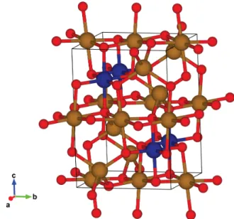
Figure 2-1: Cobalt ferrite spinel crystal structure tetrahedral sites (A - Yellow sphere, Iron) and octahedral sites (B - Navy sphere, Cobalt) for transition metal ions coordinated with oxygen (Red sphere)
tetrahedral sites (A sites) and 𝐶𝑜2+ favors octahedral sites (B sites).[43, 42, 44] 𝑍𝑛2+
doesn’t have any magnetic moment because its 3d orbitals are fully occupied. Thus 𝑍𝑛2+in A sites of ferrite will reduce the magnetic moment from the A lattice that op-poses the magnetic moment from B sites. Accordingly, doping magnetite with 𝑍𝑛2+
can be used to boost magnetic saturation of the material. On the other hand, 𝐶𝑜2+
has 7 electrons in 3d-orbitals. The substitution of 𝐹 𝑒2+ with 𝐶𝑜2+ produces distor-tion of the lattice and breaks degeneracy resulting in a higher spin-orbit interacdistor-tion. This, in turn, yields higher anisotropic energy to the Co-doped ferrite.[44]
Higher anistropic energy given by Co-doping can make wider coercive field, which enables larger hysteresis at its optimized field condition. Magnetic hyperthermia per-formance of magnetic ferrite nanoparticles is originated from the hysteric behavior during magnetization process and therefore, hyperthermic properties can be improved
Figure 2-2: A schematic graph of magnetic hyperthermia of single domain magnetic nanoparticles. 3 different models are employed to explain hyperthermic behavior at different field conditions.
by Co incorporation into the lattice. This transition metal substitution (Iron to Cobalt) induced Jahn-Teller distortions to the lattice and this changed magnetocrys-talline anisotropy in scale by an order.
2.2
Physical Theory for Specific Loss Powers(SLPs)
Specific loss power (SLP) is an intrinsic lost heat energy during magnetization process coming from hysteric characteristics of magnetic material. Heat dissipation (=magnetization process) of single domain magnetic nanoparticles cannot be under-stood only by using one theory. 3 different models - Linear response theory, the Stoner-Wohlfarth Model and dynamic hysteresis - explains magnetic nanoparticles behavior in different regime. These 3 models will be introduced in this section.
2.2.1
Linear Response Theory
Linear response theory (LRT) was first proposed by Rosensweig to explain theoret-ical power dissipation in magnetic fluids subjected to alternating magnetic fields.[45]
LRT tries to suggest dissipation relationships based on rotational relaxation of single domain magnetic particles dispersed in a liquid matrix. This model is more suit-able for explaining magnetic particles with high coercive field, strongly anisotropic, single-domain state and superparamagnetism.[46] When the ferrofluid susceptibility is given as 𝜒 = 𝜒′ − 𝑖𝜒′′, this model approximates volumetric power dissipation per
magnetization cycle as:
𝐴 = ∆𝑈 = 𝜇0𝜋𝜒
′′
𝐻02 (𝐻0− applied field) (2.1)
which is equal to the area of the hysteresis loop. Specific loss powers (SLPs) of magnetic nanoparticles can be calculated by multiplying the energy loss per cycle of the magnetization process with the applied frequency. (𝑆𝐿𝑃 = 𝐴 * 𝑓 ) Magnetic susceptibility used in the above equation also changes along the frequency change of the magnetic field.
𝜒′′ = (𝜇0𝑀 2 𝑠𝑉 ) (3𝑘𝐵𝑇 ) (𝜔𝜏𝑅) ((1 + 𝜔2𝜏2 𝑅))
(𝜏𝑅− effective relaxation time, 𝜔 = 2𝜋𝑓 ) (2.2)
The heat dissipation of magnetic nanoparticles for neuronal stimulation will be con-ducted in water, so Brownian and Néel processes will take place in parallel. The Néel process is the magnetization flip parallel to the field direction and Brownian process means physical rotation of magnetic particle toward the field direction. Neel and
Brownian mean transition times are
𝜏𝑁 = 𝜏0exp(
𝐾𝑒𝑓 𝑓𝑉
𝑘𝐵𝑇
) (𝜏0 − relaxation coefficient) (2.3)
(𝐾𝑒𝑓 𝑓 − effective anisotropic energy, 𝑉 -particle volume)
𝜏𝐵 =
3𝜇𝑉𝐻
𝑘𝐵𝑇
(𝜇 − viscosity, 𝑉𝐻 − hydrodynamic volume) (2.4)
Therefore the effective relaxation time 𝜏𝑅 should be
1 𝜏𝑅 = 1 𝜏𝐵 + 1 𝜏𝑁 (2.5)
Additionally, according to LRT, heat dissipation caused by eddy current is counted as negligible due to the small size of the particles ( 15nm).[45] LRT attempts to describe the response of the MNP ensemble using Néel-Brown relaxation under assumption that the magnetization of ferrofluid scales linearly with the amplitude of the applied field. LRT alone, however, cannot explain all hyperthermia experiments.[47, 48] If the applied field amplitude is higher than the coercivity of the MNPs, the number of MNPs aligned along the field will be saturated already, which means there will be no additional heat dissipation with increasing field amplitude. So in this case, LRT will overestimate SLP of the materials.
2.2.2
Stoner-Wolfarth Theory
When the applied field amplitude is higher than the coercive field of the MNPs, it exceeds the entire hysteresis loop and LRT is no longer valid. In this case, heat
dis-sipation can be explained through the Wohlfarth model. The original Stoner-Wohlfarth model does not take into account any thermal activation (T=0 K or when frequency 𝑓 approaches infinity). Due to the ignorance of thermal activation, magne-tization stays in one of the two minima of the energy. For MNPs aligned with their easy axis parallel to the field direction, the anisotropy barrier equals to 𝜇0𝐻𝐾 and
the hysteresis loop becomes a perfect square. In this case, the area of the hysteresis loop becomes maximum.
𝐴 = 4𝜇0𝐻𝐶𝑀𝑠= 4𝜇0𝐻𝐾𝑀𝑠 = 8𝐾𝑒𝑓 𝑓(at Φ=0) (2.6)
(Φ-angle between magnetic moment and easy axis) (𝐾𝑒𝑓 𝑓-effective anisotropic energy)
However, if all MNPs aligned with their easy axis orthogonal to the field direction, the magnetization process follows the hard axis and the hysteresis loop disappears, giving A=0. If the MNPs are arranged randomly distributed in 3D space, the corresponding coercivity is 0.482𝐻𝐾 and the area A reduces to 1.928𝐾𝑒𝑓 𝑓.[49]
There is also a model for when T is non-zero and field frequency is finite. The temperature dependence of coercivity varies depending on the angle between easy axis of the particles and the direction of applied field. For instance, if the field is parallel to easy axis, the coercivity drop is proportional to √𝑇 . Randomly distributed MNPs, however, show a decrease in coercivity with temperature, almost proportional to 𝑇3/4.[50] Usov et al.[51] took another step on this. He proposed a new dimensionless
parameter 𝜅 for the variation of the coercive field to take into account the field frequency. According to his model, the coercive field Hc is
𝜇0𝐻𝐶 = 𝜇0𝐻𝐾(1 − 𝜅0.5), (Φ=0) (2.7) 𝜇0𝐻𝐶 = 0.482𝜇0𝐻𝐾(1 − 𝜅0.8±0.05), (random orientation) (2.8) With 𝜅 = 𝑘𝐵𝑇 𝐾𝑒𝑓 𝑓𝑉 ln ( 𝑘𝐵𝑇 4𝜇0𝐻𝑚𝑎𝑥𝑀𝑠𝑉 𝑓 𝜏0
) (𝑀𝑠-magnetic saturation, 𝑉 -particle volume)
(2.9) For random orientation case, Eq. (2.8) roughly matches up to 𝜅=0.5.[46]
2.2.3
Dynamic Hysteresis
Dynamic hysteresis (DH) model treats the coherent reversal of single domain mag-netic nano particles (SDMNP) as kimag-netic process which is limited by thermal activa-tion. DH sets a time-varying energy barrier determined by the SDMNPs anisotropy energy and the Zeeman energy applied by external field. Therefore, DH defines unit-less parameters (𝜎 and 𝜉) for this kinetic process.[46]
𝜎 ≡ 𝐾𝑉 𝑘𝐵𝑇
, 𝜉 ≡ 𝜇0𝐻0𝑀𝑠𝑉 𝑘𝐵𝑇
(𝐾-anisotropy energy, 𝑉 -particle volume) (2.10)
dis-tribution.21 According to the preceding research, DH model turned out to fit well to experimental results, connecting LRT model with the Stoner-Wohlfarth model.[52]
LRT model fits well when the field strength is low enough comparing to its co-ercive field, so that magnetization is determined by relaxation process. The Stoner-Wohlfarth model corresponds to experimental results well only when the field strength is large enough to neglect the relaxation process. In between these two models, how-ever, there is a region which couldn’t be explained without DH model. DH model simplified the question with the assumption saying that whichever path the magne-tization process choose, it will be done through thermally activated kinetic process. These 3 different models together explain the behavior of SDMNPs in the entire field condition, which allow us to pick right design for multiplexing.
2.3
Magnetic nanoparticle synthesis
Synthetic routes for magnetic iron oxide nanoparticles are versatile. There are three different methods - physical, biological, and chemical. Physical methods are mainly a top-down approach and use mechanical forces, electron beam, or laser source.[53, 54] This is widely used in industrial fields but not favored in biomedical applications due to limited size and crystalline control. Biological methods use living organisms such as fungi, bacteria, plants to produce magnetic nanoparticles. This approach is get-ting attention as it can program a biological target to generate endogenous magnetic nanoparticles via gene modification. However, its low productivity, difficult size and phase control, unlike physical or chemical methods, prevent this method from being
the mainstream in magnetic nanoparticle synthesis.[55, 56] For this reason, researchers have extensively studied chemical methods and developed multiple techniques for the synthesis. Coprecipitation, microemulsion, hydrothermal, sonochemical, and ther-mal decomposition techniques are all chemical methods.[57] Among these techniques, thermal decomposition, which uses the decomposition of organo-metallic precursors in organic solvents at elevated temperature, is known to be the best in size, crys-tallinity, and phase control.[58] As the size, cryscrys-tallinity, and phase of the magnetic particles affects heat dissipating properties significantly, most of the particles in my thesis study have been prepared using this method.
2.3.1
Organo-metallic decomposition of Magnetite
nanoparti-cles
LaMer first proposed theory for a typical precipitation reaction within a closed system.42 When the concentration of free monomer [𝑀 ] increases above a critical nucleation concentration [𝑀𝐶], the solution is supersaturated. As the free monomers
get rapidly consumed through nucleation, the free monomer concentration drops be-low [𝑀𝐶] in the end and the nucleation events stop. Even though nucleation stopped,
still [𝑀 ] is higher than the equilibrium between monomer and particles with radius [𝑀𝑎], and this results in particle growth. This separation between the nucleation and
growth stages enables monodisperse nanoparticles synthesis. To explain this theory in a little more detail, we can derive thermodynamic equations from the aforemen-tioned parameters. Given supersaturation S as 𝑆 = [𝑀 ]/[𝑀∞] ([𝑀∞] – equilibrium
monomer concentration of a flat crystal), the total free energy of the system(∆𝐺𝑇)
can be drawn by the sum of bulk (∆𝐺𝐵) and surface free energy(∆𝐺𝑆).
∆𝐺𝑇 = ∆𝐺𝐵+ ∆𝐺𝑆 (2.11)
For particles with radius 𝑟,
∆𝐺𝐵 = 4/3𝜋𝑟3∆𝐺𝑉, ∆𝐺𝑆 = 4𝜋𝑟2𝛾 (𝛾-surface energy) (2.12)
As intrinsic chemical potential ∆𝐺𝑉 is ∆𝐺𝑉 = −
𝑅𝑇 𝑉𝑀
ln 𝑆, Eq. 2.11 can be re-written to
∆𝐺𝑇 = −
4𝜋𝑟3𝑅𝑇 ln 𝑆
3𝑉𝑀
+ 4𝜋𝑟2𝛾 (𝑅 − gas constant, 𝑉𝑀 − molar volume of 𝑀 )
(2.13) The former bulk term drives precursors to form particles and the latter term prevents them from aggregating. Seeing this, we can deduce there will be an energetic barrier and critical radius of nuclei to overcome (at𝜕∆𝐺𝑇
𝜕𝑟 = 0). ∆𝐺𝑛𝑢𝑐𝑙𝑒𝑖= 16𝜋𝑟3𝑉2 𝑀 3𝑟2𝑇2(ln 𝑆)2, 𝑟𝐶 = 2𝛾𝑉𝑀 𝑅𝑇 ln 𝑆 (2.14)
And by combining Eq. 2.13 and Eq. 2.14, we can tell how fast the nuclei will be formed depending on the supersaturation 𝑆.
𝑑𝑁
𝑑𝑡 = 𝐴𝑒𝑥𝑝(−
∆𝐺𝑇(𝑟𝐶)
𝑘𝐵𝑇
) (2.15)
𝑁 is the number of nuclei, and 𝐴 is the pre-exponential coefficient
𝐴 = 𝑍𝛽𝐶𝑁, 𝑍 =
√︃
∆𝐺𝑇(𝑟𝐶)
3𝜋𝑁2 𝐶𝑘𝐵𝑇
(𝑁𝐶 − # of monomers in the critical size nucleus)
(2.16)
𝛽𝐶 is the deposition rate of monomers from the solution to the nuclei surface and 𝑍
is the Zeldovich factor.43 The growth of nanoparticle can be analyzed in two different way; Fick’s first law and Fick’s second law. Fick’s first law assumes that the diffusive flux is under steady state, which means it’s reaction limited case. 𝐷 is the diffusion coefficient and 𝑟 is particle radius. [𝑀 ] and [𝑀𝑖] represent monomer concentration in
solution and particle interface each.
𝐽 = 4𝜋𝑟2𝐷([𝑀 ] − [𝑀𝑖]) (2.17)
This can be re-written using growth (𝑘𝑟) and dissolution (𝑘𝑑) rate constant.
𝐽 = 4𝜋𝑟2𝐷(𝑘𝑟[𝑀𝑖] − 𝑘𝑑) (2.18)
[𝑀𝑖] =
𝐷[𝑀 ] + 𝑘𝑑𝑟
𝑘𝑟𝑟 + 𝐷
The growth stage can also be viewed via Fick’s second law, which means particle synthesis is a diffusion limited case. 44 Suppose the molar volume of 𝑀 is 𝑉𝑀,
𝐽 = 4𝜋𝑟 2 𝑉𝑀 𝑑𝑟 𝑑𝑡 (2.20) 𝑑𝑟 𝑑𝑡 = 𝐷𝑉𝑀([𝑀 ] − 𝑘𝑑 𝑘𝑟 ) 𝑟 + 𝐷 𝑘𝑟 (from(2.18), (2.19) 𝑎𝑛𝑑 (2.20)) (2.21)
𝐾𝑒 = 𝑘𝑟/𝑘𝑑is the size dependent equilibrium constant of the reaction near the particle
surface. According to Kelvin equation, which describes the change in concentration due to the curved interface between the particle and solution, equilibrium monomer concentration [𝑀𝑒] is [𝑀𝑒] = 1 𝐾𝑒 (2.22) [𝑀𝑒] = [𝑀∞]𝑒𝑥𝑝( 2𝛾𝑉𝑀 𝑟𝑅𝑇 ) (2.23)
(𝑅-gas constant, [𝑀∞]-concentration of 𝑀 away from the particle)
From Eq. 2.21, 2.22 and 2.23,
𝑑𝑟 𝑑𝑡 = 𝑄(𝑆 − exp (2𝛾𝑉𝑀 𝑟𝑅𝑇 )) 𝑟 + 𝜉 (𝜉 = 𝐷 𝑘𝑟 and 𝑄 = 𝐷𝑉𝑀[𝑀∞]) (2.24)
From this model, we can get an idea over parameters for particle design. First, heat up rate (𝑑𝑇 /𝑑𝑡) can be regulated by the machine and this give an idea control over the size of particles. From Eq. 2.15, we can expect how many nuclei will be formed
in the nucleation stage. 𝑁𝑡𝑜𝑡𝑎𝑙 = ∫︁ 𝑡𝑒𝑛𝑑 𝑡𝑠𝑡𝑎𝑟𝑡 𝑑𝑁 𝑑𝑡 (𝑇 )𝑑𝑡 = ∫︁ 𝑇𝑒𝑛𝑑 𝑇𝑠𝑡𝑎𝑟𝑡 𝑑𝑁 𝑑𝑡 (𝑇 )( 𝑑𝑇 𝑑𝑡 ) −1 𝑑𝑇 = (𝑑𝑇 𝑑𝑡) −1 ∫︁ 𝑇𝑒𝑛𝑑 𝑇𝑠𝑡𝑎𝑟𝑡 𝑑𝑁 𝑑𝑡 (𝑇 )𝑑𝑇 (2.25) 𝑁𝑡𝑜𝑡𝑎𝑙 represents number of particles in unit volume. From Eq. 2.25 we can tell if
heat up rate is high, the total number of nuclei will decrease. It means monomer has been less consumed during nucleation stage. Therefore it will drive particles to grow larger. If the heat up rate is low, then the opposite will happen. 𝑁𝑡𝑜𝑡𝑎𝑙 will be
proportional to the integrated area in (Figure 4).
Growth stage is still undetermined whether it follows diffusion limited growth or reaction limited growth. Previous researches, however, so far show reaction limited growth more fits to the experimental results.45,46 According to these results, we can learn regulating growth speed using temperature is not that effective.
In the synthesis, solvents also have an important role. Functional groups in solvents can be used in regulating chemical potential of oxygen, and this changed chemical potential determines not just the size of the particle but also the phase of the parti-cle.47 The supersaturation above takes an important role in nucleation and growth. It can be increased by adding more precursor, setting higher heat-up rate (monomers comes quickly than their consumption), and using easily decomposable precursors.
2.4
Phase transfer of Magnetite nanoparticles
Engineered nanomaterials demonstrated various biomedical applications in the last two decades. To ensure the safety of the nanomaterials usage in novel nanomedicines, researchers tried to identify the effect of physical and chemical properties of nano-materials on biocompatibility. (such as size, surface chemistry, and surface charge). Biocompatibility refers to a biomaterial’s ability to perform its desired function with-out eliciting any undesirable local or systemic effects within the host.[59]
There are multiple factors affecting the biocompatibility of nanomaterials. How-ever, hydrophobicity is considered one of the most critical property since it determines how the nanomaterials will respond to various biological processes, such as protein adsorption[60], interaction with biological membranes[61], cellular uptake[62, 63], im-mune response[64], and hemolytic effect.[65] In general, the more hydrophobic par-ticles aggregate proteins and other nanoparpar-ticles around, causing immune system activation. Unter healthy conditions, hydrophobic cellular materials are not exposed to the external environment. However, during necrotic cell disruption or protein denaturation, these hydrophobic materials get released and interacted with cellular membranes and specific cellular receptors, and an innate immune response initiates. For this reason, hydrophobicity is considered to be a potentially dangerous cellular materials.[64]
Magnetic nanoparticles synthesized using organo-metallic decomposition method uses organic solvents that can provide high enough temperature to induce the
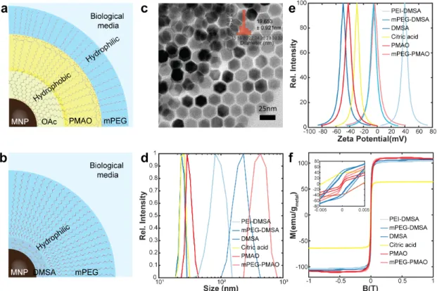
pre-Figure 2-3: Phase transfer of synthesized magnetic nanoparticles from organic phase to aqueous phase Schematic overview of phase transfer using (a)amphiphilic polymer (PMAO-mPEG) and (b)ligands exchange and sequential polymer attachment (DMSA-mPEG). (c)TEM images of iron oxides(𝐹 𝑒3𝑂4) and its
size distribution before phase transfer. (d)The particle size distribution of 𝐹 𝑒3𝑂4
collected by Dynamic light scattering (DLS) intensity measurement
cursor decomposition. Hydrophobic ligands have been used to suspend and stabi-lize nanoparticles within organic solvents, which prevents nanoparticles’ coagulation during synthesis. The undesirable toxicity coming from this hydrophobicity can be avoided by engineering the surface chemistry of nanoparticles become hydrophilic.
In this thesis work, two different surface modification techniques - polymer encap-sulation and ligand exchange - have been applied to enhance the biocompatibility of magnetic nanoparticles. As shown in Figure 2-3 (a), polymeric coating of magnetic nanoparticle using amphiphilic polymer is similar to the biophysical processes in a
T able 2.1: Summary for prop erties of phase tra n sferred magnetic nanoparticles Metho d Size distrib ution b y DLS (nm) P olydisp ersit y Index (PDI) Zeta P oten tial (m V) Magnetic Saturation (𝑀 𝑆 ) (𝑒𝑚𝑢/𝑔 𝑀 𝑒𝑡𝑎 𝑙 ) Amphiphilic p olymer PMA O 30.914692 ± 4.2548612 0.080022047 -42.446 110.2741 PMA O-mPEG 428.51531 ± 119.99377 0.078412393 -4.077 110.9548 Ligands exc hange Citric acid 24.636555 ± 2.6340977 0.018942659 -29.736 64.206225 DMSA 23.783498 ± 2.2654651 0.009073259 -49.88 103.7546585 DMSA-mPEG 218.17463 ± 68.723305 0.011431515 -6.235 106.54706 PEI-DMSA 90.250767 ± 25.530289 0.099220081 39.089 103.545706
way that both conceal hydrophobic particle via encapsulation. This method leaves oleic acid attached to the particle surface intact. Ligands attached to the particle surface influence oxidation states of particle shells and influence magnetic properties. Thus there is no significant difference in magnetic properties between before and after phase transfer when using amphiphilic polymer. [66].
Amphiphilic polymer, poly(ethylene glycol) methyl ether grafted poly(maleic anhydride-alt-1-octadecene) (mPEG-PMAO) was prepared by a similar protocol to previous studies.[67] PMAO also forms hydrophilic succinic acid when its anhydride functional group meets water, therefore without any further treatment, PMAO also used as pur-chased. Magnetic nanoparticles (2 5mg) were dispersed in 1ml of mPEG-PMAO or PMAO dissolved chloroform (concentration 10 mg/ml). The mixture was sonicated for 15 minutes and then evaporated under a vacuum. 1ml of 1x Tris-acetate-EDTA (TAE) buffer was added and sonicated for re-dispersion. Magnetic nanoparticles were spun down and washed three times with ddH2O. For the in vitro experiment, MNPs were re-dispersed in Tyrode’s solution in the final step.
On the other hand, the ligand exchange method can introduce a significant change in the properties of magnetic nanoparticles. Especially, ligand exchange using cit-ric acid introduced substantial changes in magnetic properties of nanoparticles as shown in Figure 2-3 (f) and Table 2.4. Nanoparticles were modified using a previ-ously reported method. [68] This method includes heating of the solvents mixture, which causes significant oxidation state changes. Citric acid-treated particles weren’t stable enough to do sequential polymeric coating on the magnetic particle and
pre-cipitated during the chemical process. Unlike citric acid, 2,3-Dimercaptosuccinic acid (DMSA) makes disulfide bonds one another and gives higher stability. The protocol of phase transfer using DMSA has been slightly modified by changing DMSO solvent to methanol to facilitate the drying process and washing step. [68] Due to enhanced stability, additional polymers with amine groups could be attached to the carboxylic group of DMSA using carbodiimide crosslinker chemistry.
Chapter 3
Modeling, Characterization of MNPs
and Electronic Apparatus for
Selective Heating of MNPs
3.1
Characterization of magnetic material
The use of magnetic nanoparticles in biomedical fields has been the most represen-tative examples of how nanotechnology can be applied to medical applications. These biomedical applications rely on nanoparticles’ magnetic properties, including satura-tion magnetizasatura-tion, remanence and coercivity, magnetic diameter, magnetocrystalline anisotropy, and mechanism of magnetic relaxation. Therefore, accurately quantifying these properties is crucial to guarantee the system work as intended and to maximize
the potential of iron oxide nanoparticles depending on their applications. Some of the magnetic properties can be analyzed through traditional characterization techniques using a vibrating sample magnetometer (VSM) or superconducting quantum inter-ference device (SQUID) magnetometers. However, magnetic nanoparticles in several biomedical applications undergo different environments that cannot be covered with these traditional techniques, such as exposure to alternating magnetic fields of high amplitude (< 0.05 T) radio frequencies (10s 100s kHz) or freely suspended states within solutions. This section will introduce some of the characterization techniques that can apply to these conditions.
3.1.1
Magnetic diameter and physical diameter of magnetic
nanoparticles
Iron oxides is a multi-phasic material. [69] For this reason, several parameters, such as solvent pH, oxygen chemical potential, temperature and synthesis method, can affect the phase of synthesized iron oxide nanoparticles and often result in different surface and core phases. X-ray powder diffraction (XRD) is a common techique for phase characterization requires extra steps for sample preparation. However, magnetic diameter measurements using ferrofluids and VSM can offer a fast and simple magnetic phase characterization for iron oxide nanoparticle.
Magnetic particles are freely suspended in water, enabling continuous alignment of their moments with the applied field via physical rotation. This allows the magnetic diameter of a reasonably monodisperse particle ensemble to be determined under
the assumption that the ensemble exhibits ideal superparamagnetic behavior in the limit of low applied fields. (The fitting technique employed here in the limit of low fields works equally well for fixed particles exhibiting anisotropy, provided they are randomly oriented. [46])
𝑀𝑒𝑥𝑝𝑒𝑟𝑖𝑚𝑒𝑛𝑡(𝜉) = 𝑀𝑆−𝑒𝑥𝑝𝑒𝑟𝑖𝑚𝑒𝑛𝑡𝐿(𝜉), (3.1)
Where 𝐿(𝜉) is the Langevin function, and 𝜉(𝜇𝑚𝐵)/(𝑘𝐵𝑇 ),
(𝜇𝑚 = 𝑀𝑆−𝑡ℎ𝑒𝑜𝑟𝑒𝑡𝑖𝑐𝑎𝑙𝑉𝑚, 𝑉𝑚 is the magnetic volume) (3.2)
For a magnetic field approaching 𝐵 0 mT (𝜉 ∼ 0), the Langevin function is approxi-mately linear 𝑀𝑒𝑥𝑝𝑒𝑟𝑖𝑚𝑒𝑛𝑡(𝜉) ≈ 𝑀𝑆−𝑒𝑥𝑝𝑒𝑟𝑖𝑚𝑒𝑛𝑡 × 𝜇𝑚𝐵 3𝑘𝐵𝑇 (3.3) Therefore, 𝑀𝑒𝑥𝑝𝑒𝑟𝑖𝑚𝑒𝑛𝑡(𝜉) 𝑀𝑆−𝑒𝑥𝑝𝑒𝑟𝑖𝑚𝑒𝑛𝑡 = 𝑉𝑚𝑀𝑆−𝑡ℎ𝑒𝑜𝑟𝑒𝑡𝑖𝑐𝑎𝑙 3𝑘𝐵𝑇 𝐵 (3.4) 𝑑(𝑀𝑒𝑥𝑝𝑒𝑟𝑖𝑚𝑒𝑛𝑡(𝜉) 𝑀𝑆−𝑒𝑥𝑝𝑒𝑟𝑖𝑚𝑒𝑛𝑡 ) 𝑑𝐵 = 𝑉𝑚𝑀𝑆−𝑡ℎ𝑒𝑜𝑟𝑒𝑡𝑖𝑐𝑎𝑙 3𝑘𝐵𝑇 = 𝑠𝑙𝑜𝑝𝑒 (3.5)
The magnetic diameter 𝑑𝑚 can then be determined from the magnetic volume: 𝑉𝑚 = 4 3𝜋( 𝑑 2) 3 (3.6) 𝑑𝑚 = 3 √︃ 18𝑘𝐵𝑇 × 𝑠𝑙𝑜𝑝𝑒 𝜋𝑀𝑆−𝑡ℎ𝑒𝑜𝑟𝑒𝑡𝑖𝑐𝑎𝑙 (3.7)
3.1.2
Calorimetric measurement: Specific loss power
Magnetic nanoparticles have been utilized as heat transducer using their hysteric heat dissipation during magnetization process. The heating efficiencies are referred as specific loss powers (SLPs) having 𝑊/𝑔𝑀 𝑒𝑡𝑎𝑙 as their unit. This can be directly
mea-sured by monitoring temperature change of thermally insulated ferrofluids exposed to alternative magnetic fields.
Phase transferred ferrofluid solutions were concentrated/diluted to 2𝑚𝑔𝑀 𝑒𝑡𝑎𝑙/𝑚𝑙.
A custom made series resonant circuit powered by 200W amplifier (1020L, Electron-ics & Innovation) receiving a sinusoidal signal from a function generator (Keysight 33210A) produced an alternating magnetic field. Field strength was adjusted by monitoring voltage induced in a pickup coil connected to oscilloscope (Keysight DSO-2004A). Temperature profiles were collected by fiber optic IR thermometer (Omega HHTFO-101), which is insensitive to alternating magnetic fields.
3.1.3
Dynamic magnetization captured by AC magnetometer
Regarding SLP measurements, calorimetric methods are the most mainly used approach. In this manner, dissipated heat energy is obtained from the initial tem-perature derivative over time. However, as any other calorimetric methods do, it’s also easy to get influenced by the temperature gradients of nearby environments, heat capacities of the system and the sample, and heat conductivity. Therefore, al-ternative methods have been proposed to acquire the hysteric loss of MNPs like the AC magnetometer. These methods showed more reliable SLP results with tempera-ture variations, and they even captempera-tured additional information about the magnetic behavior of the system. [70, 71, 72, 73, 74]
They have selected a solenoid design for the magnetic field generating and detecting coils. This design is intuitive and facile to fabricate, but they also had some innate shortcomings. First, an air-cooled solenoid is not always the best choice to produce a strong magnetic field efficiently with minimal input power. Ferrite, which are often used as a transformer core, has about 1500 3000 relative permeability.[75] This core can work as a magnetic lens that focuses and traps magnetic flux within the mag-netic core, and can produce stronger magmag-netic fields to targeted space with minimal energy.[76]
Also this design can give better uniformity if the field targets only a few cubic centimeter spaces. The less uniform magnetic field from the solenoid and the 3D design of the detecting coils inside AMF generating solenoid makes the detected
signal easily disturbed by the slight change of the sample/detecting coils position.
3.2
Custom design of AC magnetometer
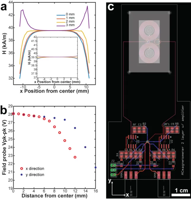
To overcome the aforementioned shortcomings, new designs were adopted to build magnetic field generator and detecting coils. Transformer ferrite E core has been shaped using diamond saw to have continuous magnetic flux within the magnetic core except the center open gap. Both magnetic core was then winded using litz wires to minimize resistance coming from skin depth effect. The core design was simulated using Finite element magnetics methods (FEMM) to ensure to have large enough area for uniform fields. (Figure3-1 a) The simulated results showed corresponding match to the actual measurements and the search coils were placed based on this simulation profile and the experimental data. (Figure3-1 b and c)
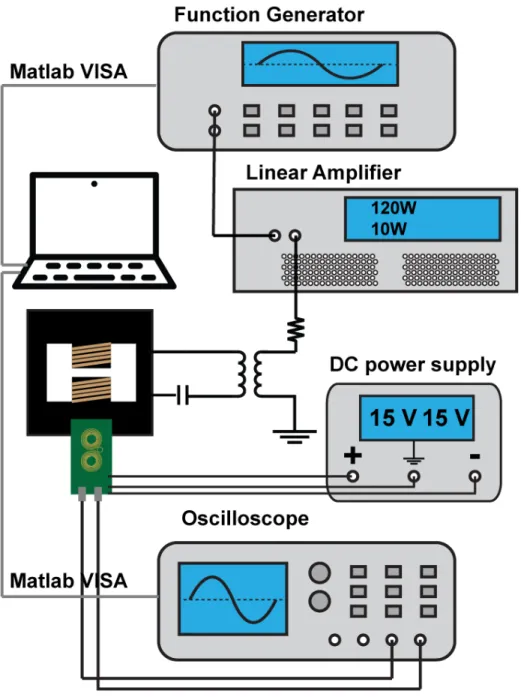
A custom designed AC magnetometer was built using 2 layer, 8mm thick printed circuit boards. Signals collected by the coil were also amplified by integrated circuit chips incorporated into the PCB. The sample holder, which contains a hollow sphere for ferrofluid injection was prepared by a 3D printer (Formlabs Form 2). After the cavity was filled with ferrofluid, it was sealed with a glue gun. The AC magnetometer was placed in the center of the gap of the electromagnet generating the AMF with the filled holder inside. The signal from a control sample (water) was subtracted from the signals measured from samples to isolate signal coming from dynamic magnetization of the MNPs.
Figure 3-1: Characterization of AC magnetometer Magnetic field profile across the magnetic core of magnetic field generator.(a) Simulated magnetic field profile using Finite Element Magnetics Methods (FEMM). (b) Peak to peak voltage profile measured using pickup coil. (c) PCB layout of AC magnetometer. Bigger white box represents the physical magnetic core size, and inner white box means magnetic uniformity ensured area.
Figure 3-2: Schematic overview of AC magnetometer and field generator setup
Figure 3-3: AC magnetometer assembly and magnetic flux density plot. (a) AC magnetometer assembly composed of AC magnetometer board and AMF gen-erator. (b) Simulated magnetostatic flux density plot calculated via Finite Element Method for Magnetics (FEMM). Our 2D AC magnetometer is placed in the center of the magnetic core gap with 5 mm margin to every edge to ensure field uniformity. (Black line – scale bar = 1 cm, green line – PCB plate, red line – spiral coil sensor)
The system was operated by the computer through Matlab VISA. (Figure3-2) The collected voltage signal was saved and later integrated after subtracting blank signals. The net signal were integrated to get hysteresis data, and the sensitivity was cali-brated using a fixed magnetic sample, VSM, and calorimetric measurements. Each hysteresis collection was again translated into SLPs and processed using Matlab and Mathematica codes to find the optimal multiplexing field conditions.
3.3
Modeling of Magnetic nanoparticles
3.3.1
Numerical Calculation of Dynamic magnetization of
Mag-netic nanoparticles
To investigate the dynamic magnetization response and hysteresis of single domain magnetic nanoparticles exposed to alternating magnetic fields, we conducted
numeri-cal numeri-calculations based on a dynamic hysteresis model implemented in Mathematica.[52, 46] Dynamic hysteresis models are most appropriate at frequencies well below the pe-riod of precession of magnetic moments described by the Landau Lifshitz Gilbert (LLG) equation. Rather than describing this precession, they instead treat coherent reversal of single domain MNPs (SDMNP) moments as a thermally activated kinetic process. A function describing the energy of possible orientations of individual par-ticle moments accounts for two main contributions: the anisotropy of a SDMNP and its Zeeman energy in the external field. The resulting energy landscape has local minima that can be envisioned to each entrap a subpopulation of the moments in an ensemble, with some escaping to the other minimum at a rate determined by the energy barrier separating the minima. The net magnetization of this ensemble is thus determined by the fraction of moments residing in each energy minimum, typically neglecting the effect of local Boltzmann distributions within the minima. Since Zee-man energy depends on the external field, which varies in time, the energy landscape is also time-variant. Consequently, the switching rate from one energy minimum to another varies periodically with the applied field. To simplify the model, magnetic anisotropy was approximated with an easy-aligned, effective uniaxial anisotropy. The anisotropy of a SDMNP and its Zeeman energy can be expressed in a form normalized to ambient thermal energy by defining the quantities 𝜎 and 𝜉 as follows.
𝜎 = 𝐾𝑉 𝑘𝐵𝑇
, 𝜉 = 𝑀𝑆𝑉 𝐵 𝑘𝐵𝑇
(𝐾 - magnetic anisotropy, 𝑉 – magnetic nanoparticle volume, 𝑘𝐵 – Boltzmann
constant, 𝑇 – 298 K room temperature, 𝑀𝑆 – saturation magnetization, 𝐵 – applied
field)
Our dynamic hysteresis model followed previous work with some variations, and more detailed descriptions of this dynamic hysteresis model can be found there.[52, 46] Unlike the previous work,[52, 46] here the pre-exponential factor of relaxation time, 𝜏0, was not fixed to 10−9 s in order to reflect the fact that the pre-exponential factor is
expected to vary with the anisotropy of SDMNP and the external field.[77, 78] From the LLG equation, neglecting stochastic thermal effects, characteristic relaxation time (𝜏𝑐) is shorter for higher applied field (𝜏𝑐 ∝ 𝜉−1).[78] By considering this correlation
[78] and the dependency of pre-exponential factor of Néel relaxation on anisotropy of the SDMNP in the Fokker-Planck equation,[77] the pre-exponential factor 𝜏0 was
made proportional to 𝜎−3/2 𝜉−1. According to Leliaert at al., 𝜏0 is varies between
10−8 to 10−12 s for 𝐹 𝑒3𝑂4.[79] Consistent with this work, our 𝜏0 was multiplied by a
suitable constant to place it within the same range:
𝜏0 = (2.04598210−7𝑠) · 𝜎−3/2𝜉−1 (3.9)
Moreover, to account for the actual particle size distribution, each MNP ensemble’s mean diameter and standard deviation were used to generate 100 random particles with a Gaussian distribution. The 𝜎 and 𝜉 values corresponding to this statistical sample of particles were entered into our numerical model and the resulting
magneti-zation responses were averaged to generate a population-averaged dynamic hysteresis loop. For side-by-side comparison, hysteresis loops calculated by the dynamic mag-netization model and collected AC magnetometer have been drawn in Figure 3-4 and Figure 3-5.
3.3.2
Finite Element Analysis on heat transfer of ferrofluid
droplets
To determine the minimal distance that prevents crosstalk between two adjacent ferrofluid droplets acting as heat sources inside a model system of a mouse brain, we applied a finite element model of heat transport.
Pennes’ bio-heat equation was used to account for the influence of blood perfusion within the brain tissue:
𝜌𝐵𝐶𝐵
𝜕𝑇
𝜕𝑡 = 𝐾𝐵▽
2 𝑇 + 𝜌
𝑏𝐶𝑏𝑤𝑏(𝑇 − 𝑇𝑏) + 𝑄 (3.10)
Where 𝜌𝐵, 𝜌𝑏 and 𝐶𝐵, 𝐶𝑏 are densities and heat capacities of the brain and blood,
respectively; 𝐾𝐵 is the thermal conductivity of the brain; 𝑇𝑏 is blood temperature;
and 𝑤𝑏 is the cerebral blood flow. 𝑄 is the power density of the heat source, and 𝑇 –
temperature. Two distinct ferrofluid injections (MNP1 and MNP2) inside the brain tissue were approximated as spheres acting as sources of constant power density Q due to the AMF. We calculated the temperature profile of the tissue as a function of
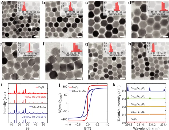
Figure 3-4: Direct, side b y side comparison of dyn amic magnetization of 𝐹 𝑒3 𝑂4 from dynamic h y steresis mo d el calculated usin g Mathematica (a-d) a n d direct A C mag n etometer measuremen t.(e-f ) (a and e, 16.3nm; b and f, 20.5nm; c and g, 25.2nm; d and h, 31.2nm) Blac k lines in (e-f ) corresp ond to VSM d a ta, rain b o w colored lo ops corresp o n d to custom-built A C magnetometer data. All data w ere collected at a frequency 𝑓 = 75 k H z.
Figure 3-5: Direct, side b y side comparison of dyn amic magnetiza tio n of 𝐶 𝑜𝑥 𝐹 𝑒3− 𝑥 𝑂4 from dynamic h ysteresis mo del calculated us ing Mathematica (a-d) and direct A C magnetometer measuremen t.(e-f ) (a and e, x =0.01, 26.7nm; b and f, x=0.03 32.5nm; c and g, x=0.14 1 9.5nm; d and h, x=0.24 18.6nm) Blac k lines in (e-f ) corresp ond to VSM data, rain b o w colored lo ops corresp ond to custom-built A C magnetometer data . All data w ere collected at a frequency 𝑓 = 75 k H z.
time. The physical parameters used in our model are summarized in the Table 3.1 Q was calculated as:
𝑄 = 𝑉𝑀 𝑁 𝑃 * 𝑆𝐿𝑃𝑀 𝑁 𝑃 * 𝜌𝑀 𝑁 𝑃 (3.11)
where 𝑉𝑀 𝑁 𝑃 is the total volume of MNPs in the droplet, 𝜌𝑀 𝑁 𝑃 is the concentration
of MNPs and 𝑆𝐿𝑃𝑀 𝑁 𝑃 is the specific loss power for the MNPs in the examined AMF
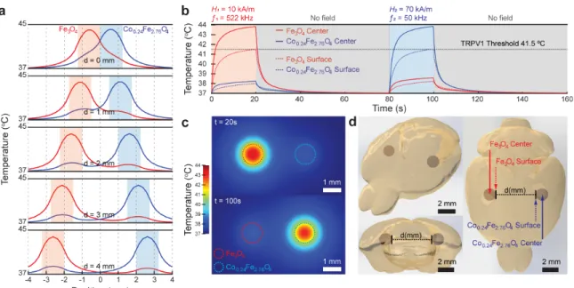
conditions of 1 = 522 kHz, H1 = 10 kA/m and 2 = 50 kHz or H2 = 70 kA/m. SLPs for MNP1 and MNP2 from the thermographic recording (Figure 4) were used in this model (Table S??). Prior research indicates that injected MNPs coated with mPEG-PMAO polymer stay mainly within injected area, even after a month. [13] Therefore, in our model, we also assumed that injected ferrofluids will maintain their shapes. To assess the minimal distance required for selective heat control, we ran multiple simulations at varying distances between ferrofluid droplets (d = 0, 1, 2, 3, 4 mm) (Supplementary Video S2 and Figure 3-6). In our model, an AMF with 1 = 522 kHz, H1 = 10 kA/m was applied for the first 20s, followed by a 60s rest epoch, then another AMF with 2 = 50 kHz, H2 = 70 kA/m was applied for 20s, followed by another 60s rest (Figure 3-6 (a)). As the distance between the droplets exceeds 2 mm, the regions of elevated temperature generated by two ferrofluid droplets are clearly separated (Supplementary Video S2 and Figure 3-6). This suggests that the multiplexed magnetothermal system can target nearby organ regions such as distinct areas of the brain even in small rodents (Figure 3-6(c)).
Figure 3-6: Temperature distribution for the two multiplexed ferrofluid droplets injected within the brain tissue and exposed to the tailored AMF conditions. (a) Temperature profiles for MNP1 (𝐹 𝑒3𝑂4, red) and MNP2
(𝐶𝑜0.24𝐹 𝑒2.76𝑂4, blue) along centers of the ferrofluid droplets separated by distance d
= 0, 1, 2, 3, 4 mm between their surfaces. Shaded areas mark the droplet positions (red - 𝐹 𝑒3𝑂4, blue – 𝐶𝑜0.24𝐹 𝑒2.76𝑂4) (b) Temperature profile of each droplet at the
center and on the surface over time (d = 2 mm). (c) Heat maps of the ferrofluid droplets within the brain tissue at t = 20 s and t = 100s (d = 2 mm). (d) Three-dimensional view of the ferrofluid droplets injected in the different hemispheres of the mouse brain.
Parameter Value Blood density 𝜌𝑏 1050 𝑘𝑔/𝑚3 [27]
Blood specific heat capacity 𝐶𝑝,𝑏 3617 𝐽/(𝑘𝑔 · 𝐾) [27]
Cerebral blood flow 𝜔𝑏 1.07 𝑚𝑙/𝑔/𝑚𝑖𝑛 [80]
Arterial blood temperature 𝑇𝑏 37𝑜𝐶 [27]
Initial and boundary temperature 𝑇0 37𝑜𝐶 [27]
Brain specific heat capacity 𝐶𝑝,𝐵 3630 𝐽/(𝑘𝑔 · 𝐾) [27]
Brain density 𝑟ℎ𝑜𝐵 1065 𝑘𝑔/𝑚3 [27]
Brain thermal conductivity 𝐾𝐵 0.51 𝑊/(𝑚 · 𝐾) [27]
𝐹 𝑒3𝑂4 ferrofluid concentration 115.534 𝑚𝑔𝑀 𝑒𝑡𝑎𝑙/𝑚𝑙
𝐶𝑜0.24𝐹 𝑒2.76𝑂4 ferrofluid concentration 64.674 𝑚𝑔𝑀𝑒𝑡𝑎𝑙/𝑚𝑙
Chapter 4
Selective modulation on cellular
signalling via multiplexed bulk
heating of MNPs
4.1
Background and Motivation
Emerging biomedical applications of heat dissipation by magnetic nanoparticles (MNPs) in alternating magnetic fields (AMFs) include control of cell signaling, gene expression, and drug release.[81, 39, 27] Despite the unparalleled access to deep phys-iological targets offered by magnetic fields, independently addressing bphys-iological path-ways via focused AMF application is typically infeasible. One recent solution borrows methodology from magnetic particle imaging, superimposing a magnetostatic field to
restrict MNP heating to points of vanishing field magnitude.[52, 46] Although this approach can offer targeted heating with millimeter resolution, it is ill-suited to freely moving subjects or targets with spatial overlap. Here, we present a materials-based approach for independent magnetic control of multiple sites or processes based on “magnetothermal multiplexing,” the independent heating of MNPs with differing co-ercivities upon exposure to paired AMF conditions.6 We report the model-driven development of a suitable materials system and use it to demonstrate selective actu-ation of intracellular calcium ion influx in vitro.
When MNPs are exposed to AMFs, they dissipate heat arising from thermody-namic irreversibility in the response of their magnetization. This irreversibility can be graphically represented by hysteresis loops, which enclose an area corresponding to the heat dissipated per magnetization cycle. While all models for heat dissipation by MNPs can be understood as methods for predicting hysteresis loops, the “dynamic hysteresis” model does this by describing magnetization response as a kinetic pro-cess determined by an energy landscape consisting of the effective anisotropy energy and the configurational energy of the MNP moment in the applied AMF.[82, 48] The relevant energy contributions depend on the MNP materials properties (effective magnetic anisotropy 𝐾𝑒𝑓 𝑓, saturation magnetization 𝑀𝑆, volume V), temperature T,
and the applied AMF conditions (field amplitude H and frequency ). According to the dynamic hysteresis model, the MNPs that produce large hysteresis loops combine high 𝑀𝑆 with anisotropy barriers sufficient to prevent spontaneous reorientation of