SHREDDER
by
Alexander Timothy Chen
SUBMFTED TO THE DEPARTMENT OF MECHANICAL ENGINEERING IN PARTIAL FULFILLMENT OF THE REQUIREMENTS FOR THE
DEGREE OF
BACHELOR OF SCIENCE at the
MASSACHUSETTS INSTITUTE OF TECHNOLOGY June 1990
Copyright @ Massachusetts Institute of Technology, 1990. All rights reserved.
Signature of Author
Department of Mechanical Engineering June 4, 1990 Certified by I Accepted by MASSACHUSE-TTS INSTITUTE OF TECHNOLOGy
JUL
09
1990
LIBRARIES ARCHiIVEsProfessor David Gordon Wilson Thesis Supervisor
Professor Peter Griffith Chairman, Department Committee
DESIGN OF A HUMAN-POWERED LEAF AND BRANCH
SHREDDER
by
Alexander Timothy Chen
Submitted to the Department of Mechanical Engineering on June 4, 1990 in partial fulfillment of the requirements for the degree of Bachelor of Science.
Abstract
A human-powered device to "shred" leaves and branches would provide exercise for fit people. Since this is a novel concept, experiments were conducted to determine the shear strength of wood and the effect of the angle of cut on the cutting forces. The cutting subassembly was designed, and a prototype blade spine was fabricated from a fiberglass composite. No formal tests on the prototype were conducted.
Thesis Supervisor: Title:
Professor David Gordon Wilson Professor of Mechanical Engineering
Dedication
This thesis is significant in that it represents the end of my career at M.I.T. I would like to first thank my parents, Arthur C. M. Chen ('61) and Carole Z. Chen, for their incessant, though not always apparent, support. My sister, Holly S. Chen, also deserves thanks for her encouragement, but mostly for her youthful wisdom and insight, which was perhaps more useful to me at this stage of life than the advice of others. To Professor Woodie C. Flowers, I owe my success in design; through 2.70, 2.73, and 2.944, he gave me the confidence to be a good designer, and not to mention a great deal of advice. To William J. Moliski, a great friend who had nothing to do with this thesis, I wish continued success during his remaining year here. And last but certainly not least, to P. Jennings Daniel I give thanks for encouragement, understanding, and companionship.
-4-Table of Contents Abstract Dedication Table of Contents List of Figures 1. Introduction 2. Properties of Wood
2.1 Background and Prior Art
2.2 Shear Strength: Charpy Impact Test 2.2.1 Experimental
2.2.2 Results
2.3 The Dependence of Cutting Energy on Cutting Angle 2.3.1 Experimental
2.3.2 Results
3. Design and Prototype Fabrication
3.1 Background and Preliminary Design Concept 3.2 Cutter Subassembly
3.2.1 Design
3.2.2 Prototype Fabrication 3.2.3 Test and Evaluation 4. Conclusions and Recommendations
Appendix A. Raw Data from Charpy Impact Test Appendix B. Raw Data from Cutting Angle Experiment
2 3 4 5 6 7 7 8 8 8 13 13 13 18 18 19 19 23 25 26 28 30
List of Figures
Figure 2-1: Charpy impact test apparatus 2.2.1
Figure 2-2: Charpy V-Notch test specimen 2.2.2
Figure 2-3: Top view of a Charpy V-Notch test specimen 2.2.2 Figure 2-4: Charpy impact test of square oak specimens 2.2.2 Figure 2-5: Charpy apparatus adapted to measure cutting energy 2.3.1 Figure 2-6: End view of samples cut by the adapted Charpy test apparatus 2.3.2 Figure 2-7: Top view of adapted Charpy test samples cut at 900 2.3.2 Figure 2-8: Dependence of cutting energy on angle of cut 2.3.2 Figure 3-1: Schematic of the overall HPS design 3.1 Figure 3-2: Schematic of cutting assembly arrangement 3.2.1
-6-Chapter 1
Introduction
The advent of Earth Day on April 22, 1990, is an indicator of the increasing public awareness of environmental issues throughout the world. Recycling natural debris, such as the leaves and branches collected during one's gardening activities, is as important as recycling cans and bottles and plays a large role in the entire conservation theme. The mechanical break-up of such material hastens the recycling process, and the invention of a human-powered device to do this is a worthwhile pursuit. Such a device might also be a good form of exercise.
In order to successfully design any machine tool, the material properties and dynamic response of the intended workpieces must be known. For a cutting device such as a human-powered leaf and branch shredder (HPS), the limiting property is the resistance of wood to a cutting or shear force. The same resistance exhibited by leaves is not considered a critical factor, although their behavior under a shear force will certainly affect the overall success of the design. A patent search and library research proved unsuccessful in the quest for such information, and so a variety of experiments were conducted with a modified Charpy impact tester in order to find the shear strength of wood and the dependence of cutting forces on the cutting angle.
Once the needed quantities and relationships were found, the design stage could begin. A preliminary overall design was conceptualized, and the detailed design of the actual cutter was completed and partially built. The cutter spine, constructed from fiberglass-reinforced composite, was not formally tested.
Chapter 2 Properties of Wood
2.1 Background and Prior Art
Since the advent of lightweight metals and more recently, advanced composites, research conducted on the properties of wood has diminished to virtual non-existence. It seems, however, that a significant amount of research was conducted in the 1950s, and there are many books on the subject from that decade. Because of the inherent variations in climate, soil, sunlight, and other factors, the properties of wood vary greatly, even within a particular species. Material properties are thus listed according to species, with a given set of conditions for growth, and are usually given in ranges.
Shear strength may be described as a measure of a material's ability to resist forces that tend to cause one part of the material to slide or slip relative to another part adjacent to it. Thus the shear strength of wood is directly related to its workability in terms of cutting. The shear strength of wood was listed in a number of sources, but only for the case of a force acting parallel to (along with) the grain. This is because the shear strength of wood across the grain may be treated as infinite, since wood fails by tension, crushing across the grain, or shear along the grain before it shears across the grain. [Wangaard 50] In an informal experiment, a hollow-ground paper shear was used to crush some samples into two pieces, thus confirming this notion. For samples of "clear" wood in both a green and an air-dry condition, shear strength in the parallel direction ranged from a few hundred to several thousand psi, and values for tensile strength in the direction perpendicular to the grain were typically below one thousand psi. [Forest 55]
-8-A search of patents granted after 1975 revealed no useful information, since most of the devices which acted by shear were large devices used to cut entire trees, with virtually no limits on power.
2.2 Shear Strength: Charpy Impact Test
2.2.1 Experimental
The configuration of the Charpy impact tester varies from model to model, but it generally consists of a heavy, free-fall pendulum which strikes the sample at the angular position with the lowest potential energy. Actual contact between the pendulum and the sample is made with an angular striking head. Charpy energy is found by measuring the angle of the follow-through swing, and thus a device to measure or convert the angle of follow-through is included. The specimen rests on a mounting block which opposes the forces of the striking pendulum and thus holds the sample in place. Figure 2-1 contains a sketch of the Charpy apparatus used for this experiment.
Two types of samples were tested. All were roughly 55 x 10 x 10 mm, but half of the samples had a 450 notch cut into the middle, which reduced the height of these samples by about 2 mm. For each trial, the sample was placed in the mounting block, the pendulum was raised and released, and the angle of the follow-through swing was recorded. The measured angle was then converted into the energy required to break the sample.
2.2.2 Results
As predicted by background research, the primary mode of failure in the Charpy impact test was tension, with some element of shear along the grain. Because of the fibrous nature of wood, the v-notch had the effect only of reducing the sample's cross-sectional area, and did little in terms of producing a stress concentration. Photographs of some samples are presented in figures 2-2 and 2-3.
2
5
6
7
Figure 2-1: Charpy impact test apparatus -- 1) impact head,
2) pendulum arm, 3) release lever, 4) angle gauge,
5) needle, 6) mounting block, 7) base and supports
The energy required to break the samples is found simply by calculating the difference in potential energy between the maximum height of a free swing (in the absence of a sample) trial and the maximum height of the follow-through swing during a regular trial. This accounts for all forms of internal damping in the system. This may be expressed initially as
-t0-(a)
(b)
Figure 2-2: Charpy V-Notch test specimen. The mode of failure is tension -- a) Top view, b) End view
Figure 2-3: Top view of a Charpy V-Notch test specimen. The sample failed by both tension and shear parallel with the grain direction.
The energy in each of these two terms is the quantity mgl multiplied by the sine of some angle. If $ is the angle of free swing minus 900, 0 is the follow-through angle less 900, m is the mass of the pendulum, g is the gravitational constant, and I is the length from the axle to the center of mass of the pendulum, then this formula reduces to
Charpy Energy = mgl [ sin() - sin(O) ] (2.2)
The results are presented in figure 2-4 on the following page. ft-lbs, and are shown as a function of cross-sectional area.
Values ranged from 46 to 89
This unusual behavior of wood under a shearing force across the grain was discovered as a result of these experiments. At this point I returned to my references, only
75 -12-100 t 75t Energy _o. (ft-lbf) 25t 50 100 125 150 Cross-sectional Area (mm2)
Figure 2-4: Charpy impact test of square oak specimens. Unshaded circles represent notched specimens, shaded unnotched.
to discover that the same explanation was the reason why no transverse shearing data were presented. Not having obtained any useful data, a new set of experiments was designed and are described in the next section.
00 0
00 *0
2.3 The Dependence of Cutting Energy on Cutting Angle 2.3.1 Experimental
These experiments were carried out with the same Charpy apparatus as used before, but with a special adapter designed to hold a blade, shown in figure 2-5. This adapter, made from aluminum, allows a blade to be positioned at a variety of angles, with minimal changes in mass, center of mass, and initial striking position. For simplicity, only three cutting angles -- 200, 450, and 900 as measured from the ground -- were tested, since we wished to observe only a general trend and to obtain approximate values to guide the cutter design. Round samples of 3/8" and 1/2" diameter were used.
2.3.2 Results
The energy required to cut the specimens is found using the same formula as the Charpy impact test, equation (2.2), with an adjusted value of the mass m. With this exception, the changes in the system parameters are considered negligible. Photographs of some cut samples are shown in figures 2-6 and 2-7.
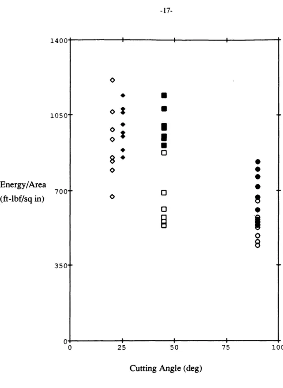
The results are depicted graphically in figure 2-8 as the cutting energy per unit area (ft-lbf/in2) versus the blade angle, and values range from 440 to 1220 ft-lbf/in2. Contrary to
the anticipated trend, the minimum cutting energy comes from a blade angle of 900
--perpendicular to the cutting motion! This, however, may be the result of the design of the experiment: a large component of the reaction force acts along the length of the pendulum rod and terminates at the pendulum axle. This force component, which increases as the cutting angle decreases, was large enough to cause vibrations and significant deflections in the pendulum rod, and would be an interesting topic for future research. Of additional curiosity, no sample was cut completely through, irregardless of the angle of cut. Rather, each sample was cut until the remaining uncut portion of the sample was unable to withstand the bending load exerted by the blade and failed by tension or one of the other
-14-2 4 4D 4D 4D
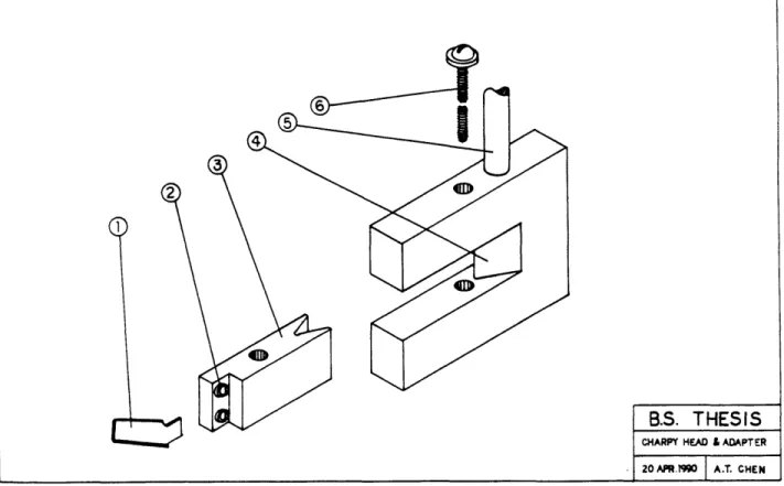
Figure 2-5: Charpy apparatus adapted to measure cutting energy -- 1) blade, 2) blade mounting screws, 3) adapter block, 4) Charpy impact head,
5) pendulum arm, 6) mounting bolt for adapter block
modes. This may not be a factor for a slower cutting action of clamped, cantilevered branches.
B.S. THESIS
CHARPY HEAD & ADAPTER
20APR.199 A.T. CHEN
(a)
(b)
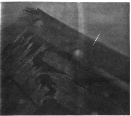
Figure 2-6: End view of samples cut by the adapted Charpy test apparatus -- a) cut angle=250, b) cut angle=450
-16-(a)
(b)
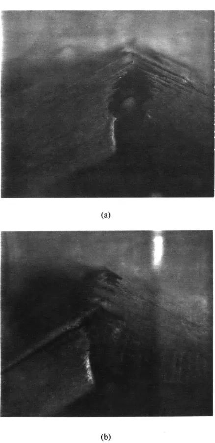
Figure 2-7: Top view of adapted Charpy test samples cut at 900 --a) tensile failure mode, b) tensile failure with shear component.
__ * I. 1050t Energy/Area (ft-lbf/sq in) + U 0?
*
U
008
. 00 0 08 700t 350-0 25 50 75Cutting Angle (deg)
Figure 2-8: Dependence of cutting energy on angle of cut. Shaded symbols represent 1/2" samples, unshaded 3/8". 1400
100 a
-18-Chapter
3
Design and Prototype Fabrication
3.1 Background and Preliminary Design Concept
The concept of a device to shred leaves and branches is old, but as previously mentioned, the concept of a human-powered version of this device is new. A large number of gas- or electric-powered shredders are available today, in a variety of sizes. All of these employ a set of blades or pulverizers rotating at high speeds. Those in the lower power ranges typically have many problems, particularly with clogging. Besides the issue of feed-rate versus power, we are limited in our human-powered device by the power output of a human, which is typically much less than even the smaller commercial shredders require. Since the properties of wood dictate the minimum cutting force required, we must reduce the power requirements by reducing the blade velocity. Thus a well-designed human-powered shredder will not be so much a shredder as a cutter.
Maximum human output can be achieved by many configurations, but a pedal-powered device is the simplest to obtain parts for, and this method has the further advantage that a transmission (derailleur) is already built-in and is relatively easy to install. This approach will necessarily involve some sort of incremental timing mechanism, since the pedalling motion is inherently continuous while our cutter is not. Furthermore, the power-stroke should remain constant, and so the gearing or actuator should also be designed to match any changing forces or moments inherent in the cutter design. For obvious safety reasons, an overload cam or similar mechanism should be incorporated into the cutter or drive mechanism.
The material feeder must also be incremental, but synchronized 1800 out-of-phase with the cutter. By combining the feeder with the clamping mechanism, we reduce the number of parts while at the same time making the design more energy-efficient: if the branches are never unclamped, then no energy is lost in an unclamp-advance-clamp cycle, which allows the branches to store and release potential energy in a spring-like fashion. To facilitate a two-stage advance/clamp-cut cycle, this portion of the HPS might incorporate a medium-sized roller mounted opposite the anvil and material slide (or passive conveyor-style belt). The roller mounting should be spring-loaded in order to accommodate varying load geometries, but with a maximum clearance of about 1/2".
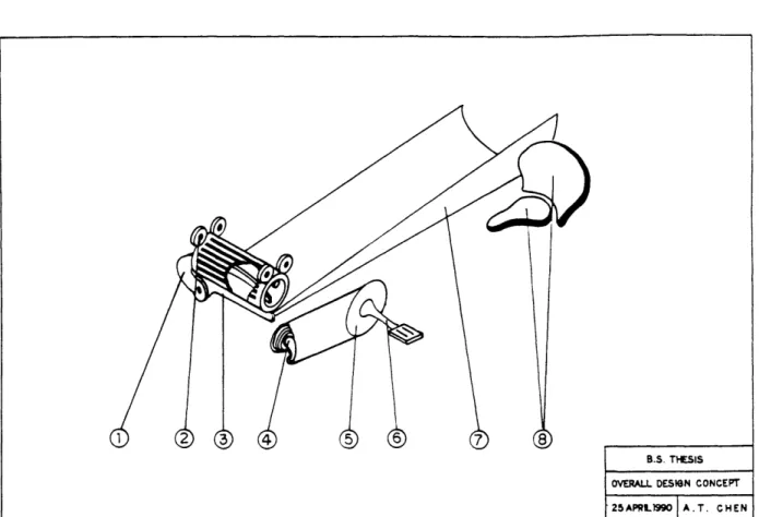
Branches and leaves are actually cut by the device explained in the next section. The overall design is presented schematically in figure 3-1.
3.2 Cutter Subassembly
3.2.1 Design
The cutting motion with the smallest required cutting force will cut only one branch at a time. To reduce losses incurred by compressing cantilevered branches, the branches should be clamped directly against an anvil which opposes the force of the cutting motion. Unfortunately, a simple geometry which satisfies both of these conditions, while utilizing the ideal 900 cutting angle found in chapter one, does not exist. Minimization of the required cutting force is the most important specification, and thus if the branches are to be lined up along the length of an anvil, the blade must have a slight angle as it contacts the branches, much like a guillotine. The cutter design with the smallest frictional losses is a pivoting blade, since there is friction only in one pivot and at the blade/branch and blade/anvil interfaces. Other designs generally incorporate additional pivots or sliders which increase frictional losses. The optimal design then, is similar to a paper shear, but
-20-B.S. THESIS
OVERALL DESIGN CONCEPT
25APRL)990 A.T. CHEN
Figure 3-1: Schematic of the overall HPS design -- 1) cutter spine, 2) drive/pinch roller, 3) anvil, 4) gearset/derailleur,
5) main gear, 6) crank/pedal 7) feed slide, 8) seat/back rest
with a number of differences. The blade is offset from the pivot point to reduce the height which the blade must lift in order to accomodate a branch near the pivot. This configuration also allows the blade to pass through a slot with closed ends. Also, the curve of the blade is designed to maintain a constant cutting angle, and is shaped concave downwards so the cutting forces tend to push the branches toward the center of rotation, where the cutter affords the greatest mechanical advantage. A paper shear is curved in the opposite way. Figure 3-2 shows a schematic of the cutting assembly arrangement.
49 3 7 2 B.S. ThESIS HIAN-POWEED SHREDDER 10 APRL 1990 AT. CHEN
Figure 3-2: Schematic of cutting assembly arrangement --1) spine, 2) pivot base, 3) pivot shaft, 4) blade, 7) anvil,
8) feed table, 9) cutter return/contact spring
necessary. The spine backing the blade must be very stiff in order to withstand the bending moments involved. The worst case exists when the device is unable to cut a branch near the pivot point, and the spine then acts as a cantilever beam. The deflection of a cantilever beam is given by
F- 3
(3.1)
3EI
where F is the force applied at the end of the beam, I is the beam's length, E is the elastic modulus, and I is the moment of inertia. For a rectangular beam, the moment of inertia is
-22-I W= ,
(3.2)
12
where b is the base width of the beam and h is the height. Combining equations (3.1) and (3.2), we arrive at a relationship for the deflection of a rectangular cantilever beam
4F13
(3.3)
Ebh3
Thus, in order to maximize stiffness, we desire a beam that is very tall and thin. If we initially assign values for the height and width of the beam as 1-1/2" and 3/8", respectively, we find the deflection when cutting two branches (1/2" each) to be approximately 1/8" for a steel spine, which is not unreasonable. To achieve the same stiffness with an aluminum spine, the thickness and/or height become restrictive. In the actual design, the free end of the spine need not have the maximum height, since the bending moments are significantly lower.
It is unlikely that the forces acting on the cross-section of the beam will be uniform. In the worst case, the blade pushes up on the spine from one bottom comer and the actuator pulls down on the diagonally opposite top comer, thus producing a twisting moment. Under these conditions, torsional shear stress becomes a concern. If Mt is the twisting moment, then torsional shear stress t is given by
8Mt o.6 b
=.375 1 + 0 . (3.4)
hb2 h
For our geometry and loading, the maximum shear stress was found to be 4232 psi, which is well within the performance limits for most structural materials.
One final concern is the degree of torsional deflection given by the same twisting moment Mt. If the beam is modeled as a torsional spring, then the degree of twist, a, is given by the twisting moment divided by the torsional spring constant, Ka, or
Mt
a = --. (3.5)
The torsional spring constant is given by the relationship
Ghib3 b / b
Ka = 5.3 3 1-0.63 ( - - _b_ (3.6)
S161 1 h 120e
which combined with equation (3.5) gives us a torsional deflection of 0.670, which is quite small.
Given these parameters for the spine geometry, the cutter was designed with the shape seen in figure 3-3. The blade spans an arc of 10", leaving an 8" cut across the anvil.
3.2.2 Prototype Fabrication
Although the original design calculations were based on the material properties of steel, parts made from advanced composite materials are often simpler to fabricate, and still afford great stiffness properties. Additionally, composites are light-weight and offer the additional advantage of manufacturing flexibility. And so, with the intention of using a plaster cavity mold for a carbon-fiber-reinforced composite, a wooden male mold of the spine was initially constructed. Fiberglass, however, is more resistant to stress concentrations than graphite fibers, and since the support spine of a wood shredder is likely to be subjected to nicks and cuts, fiberglass composite is more likely to produce a robust part. Because of this fact and the additional problems of time, cost, and equipment limitations, the reinforcing material was changed from carbon-fiber to fiberglass.
-24-1 2 3
B.S. THESIS
HUMAN - POWEE SHEXXR D AR& SO A T. CHEN
Figure 3-3: Cutter design -- 1) Spine, 2) Pivot Base, 3) Pivot Shaft, 4) Blade, 5) Branch, 6) Roller, 7) Anvil
24 pieces with approximately the same profile as the spine. A clean, smooth working surface was prepared and covered with a plastic wrap. The initial layer of fiberglass was placed directly on the plastic wrap and coated with a mixture of 32 fl. oz. of polyester resin and 11 cc of methyl ethyl ketone (MEK) peroxide. The resin was sequentially applied to each piece of the fiberglass mat, and extra layers were added in a region at the curved end for mounting the spine to a shaft. The final layered form was covered with another sheet of plastic wrap and left to cure under pressure at 65 F for 24 hours. Pressure was achieved by stacking solid weights on top of a piece of foam rubber. Once hardened, the edges were cut
and sanded to the correct shape, and holes were drilled for mounting a blade and a 1/2" shaft.
3.2.3 Test and Evaluation
Although no formal tests were conducted, the finished part was well-designed and -constructed. The spine stiffness was tremendous torsionally, as well as in both the vertical and horizontal directions. This fact was verified with a simple bending test, conducted at the hands of my very large friend Roland. Unfortunately, the laying surface was slightly warped and thus the spine curvature through the thickness is oriented opposite to the original design. Additional defects include some surface imperfections produced by bubbles which formed during the curing process. Otherwise, the part is quite satisfactory.
-26-Chapter 4
Conclusions and Recommendations
The different experiments carried out on wood revealed some interesting facts. The resistance of wood to a shear force transverse to the grain direction is dictated by its tensile properties and its shear strength along the grain. Wood is cut the "cleanest" at approximately a 450 angle, but the least amount of energy -- and hence the smallest force --is required at a 900 angle, i.e. straight on. Wood also tends to break before being cut completely through. Part of the cutter design is now completed and built. There is little else to be said about the HPS at this stage, except that there is a tremendous amount of work left to be done. Suggestions for further work are perhaps best summarized as follows:
Shear Strength of Wood: Charpy Test
" Tensile tests conducted by pulling parallel to the grain would provide useful information about the strength of wood when sheared across the grain, since this was the predominant mode of failure in the Charpy tests. Charpy tests oriented parallel with the grain might reveal interesting data as well. For dry wood, most of these figures are currently available.
" Tests on "green" and knotty wood might prove useful, since the dynamic properties of these kinds of samples are likely to be quite different from clear, dry ones.
Dependence of Cutting Force on Cutting Angle
" The vertical component of the reaction force was quite large in the modified Charpy test, and perhaps a better test without this relationship should be devised. A better test would also eliminate "pinching," and thus frictional energy, between the blade and the sample halves.
" Tests on "green" and knotty wood again might prove useful. "Green" wood might help to find the lower limits of the required cutting force, and knotty
samples might help to find the upper limits. "Green" wood might also provide a better understanding the effect of bending on the cutting action.
* Tests using toothed blades or rotary saws might reveal useful information about these cutting actions which could be applied to the HPS design.
Design of Cutter Subassembly
* An extremely smooth surface with a concave-downward profile would be best for laying up the cutter spine.
* A blade of ordinary steel is probably sufficient for early stages of prototyping and testing.
* A roller/clamp subassembly would be the logical pursuit of the next HPS designer.
-28-Appendix A
Raw Data from Charpy Impact Test
Notched Samples
Area (mm x mm) Angle (deg) Energy (ft-lbf)
1 89.56 109.5 63.79 2 94.71 108.0 66.68 3 90.26 119.0 46.18 4 90.89 110.0 62.83 5 96.81 103.5 75.49 6 90.20 116.0 51.60 7 95.23 100.5 81.46 8 99.10 105.5 71.55 9 100.04 106.0 70.57 10 97.20 98.0 86.48 11 88.35 115.0 53.43 12 101.03 98.5 85.48
Unnotched Samples
Area (mm x mm) Angle (deg) Energy (ft-lhf)
1 111.94 113.0 57.15 2 109.20 107.0 68.62 3 109.20 111.0 60.93 4 100.89 110.0 62.83 5 106.91 105.0 72.53 6 109.80 101.5 79.47 7 94.27 107.0 68.62 8 99.09 106.5 69.60 9 111.29 97.0 88.50 10 113.18 97.0 88.50 11 108.16 97.0 88.50 12 111.30 101.0 80.46 13 104.03 107.0 68.62 14 103.00 110.0 62.83
-30-Appendix B
Raw Data from Cutting Angle Experiment
Thin Round Samples (3/8" dia.)
Cut Angle (deg) Swing (deg) Energy (ft-lbf) E/A
1 90 118.5 53.90 488.04 2 121.0 48.85 442.25 3 114.0 63.30 573.17 4 115.0 61.18 553.97 5 114.0 63.30 573.17 6 110.0 71.95 651.40 7 116.0 59.08 534.93 8 116.0 59.08 534.93 9 116.5 58.04 525.47 10 120.0 50.85 460.43 11 45 112.0 67.59 612.01 12 108.0 76.35 691.29 13 116.0 59.08 534.93 14 114.0 63.30 573.17 15 115.0 61.18 553.97 16 115.0 61.18 553.97 17 116.0 59.08 534.93 18 99.0 96.72 875.74 19 116.0 59.08 534.93
Thin Round Samples (Continued)
Cut Angle (deg) Swing (deg) Energy (ft-lbf) E/A
20 20 96.0 103.65 938.48 21 109.0 74.14 671.29 22 83.0 133.88 1212.16 23 101.0 92.13 834.18 24 94.0 108.30 980.52 25 103.0 87.58 792.91 26 100.0 94.42 854.93 27 90.0 117.61 1064.84 28 100.0 94.42 854.93 29 100.0 94.42 854.93
-32-Thick Round Samples (1/2" dia.)
Cut Angle (deg) Swing (deg) Energy (ft-lbf) E/A
1 90 70 163.27 831.53 2 94 108.30 551.54 3 80 140.79 717.05 4 84 131.56 670.05 5 93 110.62 563.39 6 76 149.91 763.47 7 80 140.79 717.05 8 89 129.94 610.84 9 95 105.97 539.71 10 73 156.64 797.77 11 45 55 194.19 988.98 12 54 196.08 998.64 13 60 184.36 938.95 14 45 212.01 1079.78 15 59 186.37 949.18 16 59 186.37 949.18 17 54 196.08 998.64 18 63 178.22 907.67 19 37 224.23 1142.01 20 63 178.22 907.67 21 25 45 212.01 1079.78 22 57 190.32 969.30 23 37 224.23 1142.01 24 59 186.37 949.18 25 53 197.96 1008.18 26 65 174.03 886.34 27 59 186.37 949.18 28 57 190.32 969.30 29 47 208.66 1062.70 30 68 167.62 853.69
References
[Calibration 54] [Desch 73] [Forest 55] [Wangaard 50] [Wee 89]Calibration of Charpy Impact Test, No. 208
Massachusetts Institute of Technology, 1954. Desch, H. E.
Timber: Its Structure and Properties.
St. Martin's Press: New York, 1973.
Forest Products Laboratory, U.S. Forest Service.
Agriculture Handbook No. 72: 'Wood Handbook'.
U.S. Dept. of Agriculture: Washington D. C., 1955. Wangaard, F. F.
The Mechanical Properties of Wood.
John Wiley & Sons, Inc.: New York, 1950. Wee, Kee Young.
Cutting Data for the Design of a Human-Powered Shredder. June, 1989.