Design of an Automated On-Car Brake Lathe
by
Andrew Kirk Wilson
B.S.M.E., Santa Clara University (1999)
Submitted to the Department of Mechanical Engineering
in partial fulfillment of the requirements for the degree of
Master of Science in Mechanical Engineering
at the
MASSACHUSETTS INSTITUTE OF TECHNOLOGY
June 2001
©
Massachusetts Institute of Technology 2001. All rights reserved.
Author___________
Department of Mechanical Engineering
May 23, 2001
Certified by
Samir A. Nayfeh
Assistant Professor of Mechanical Engineering
Thesis Supervisor
Accepted by
Ain A. Sonin
Professor of Mechanical Engineering
Chairman, Department Committee on Graduate Students
BARKER
MASSACHUSETTS INSTITUTE OF TECHNOLOGY
Design of an Automated On-Car Brake Lathe
by
Andrew Kirk Wilson
Submitted to the Department of Mechanical Engineering
on May 23, 2001, in partial fulfillment of the
requirements for the degree of
Master of Science in Mechanical Engineering
Abstract
An on-car brake lathe resurfaces disk-brake rotors by rotating them "in place" and
making a light cut along the surface of the disk. The primary goal of this thesis is to
develop an automated cutting head for an on-car brake lathe. The new cutting head
must produce a surface finish that matches or exceeds that of the current (manual)
cutting head. Pro-Cut International, a leading manufacturer of on-car brake lathes,
developed functional requirements and cost constraints for the automated cutting
head.
Technical challenges include design and fabrication of low-cost precision linear
bearings and actuators with dynamic stiffness sufficient to suppress chatter.
During this thesis, two prototype cutting heads were designed, manufactured, and
tested. The first prototype employed modular linear bearings, and produced
unac-ceptable surface finish due to chatter. Cutting-tip vibration measurements combined
with modal testing showed that chatter was caused by low structural stiffness of the
modular bearing rails.
A second prototype employing a unitary ground bearing system produced an
acceptable surface finish of 70
1-inch at 0.015" depth of cut per side. The key
compo-nents of this design can be extruded and sliced to form the assembly, thereby meeting
cost constraints.
Thesis Supervisor: Samir A. Nayfeh
Contents
1 Introduction
1.1
Background.. . . . .
...
1.2 Current Design Usage . . . . 1.3 Design Requirements . . . .
2 Machine Design
2.1
Design Approach . . . .
2.1.1
Rotary vs. Linear . . . .
2.1.2
Motor Type Selection . . . . .
2.1.3
Lead Screw and Motor Sizing
2.1.4
Inboard-Outboard Positioning
3 Kinematic Design
3.1 Exact Constraint Theory . . . .
3.2 Bearing Replication . . . .
4 Prototype 1
4.1 Exact Constraint Theory Applied
4.2 Mockup Testing . . . .
4.2.1
Goals . . . .
4.2.2
Methods . . . .
4.2.3
Results . . . .
4.2.4
Conclusions . . . .
11
11
12
12
15
15
15
18
19
27
29
29
31
33
33
37
37
37
38
42
. . . . . . . . . . . . . . . . . . . . . . . . . . . . . . . . . . . . . . . . . . . . . . . . . . . . . . . . . . . . . . . . . . . . . . . . . . . . . . . . . . . . . . . . . . . . . . . . . . . . . . . . . . . . . . . . . . . . . . . . . . . . . . . . . . . . . . . . . . . . . . . .5 Prototype 2
5.1 Goals... ...
5.2 Description of Redesign . . . .
5.3 Results... . . . .. . .. . 5.4 Conclusions . . . . .. . . . .
6 Non-Linear Flexure Design
6.1
Desired Characteristics . . . .
6.2
Belleville Washer . . . .
6.2.1
Belleville Geometry . . . .
6.2.2
Theory and Limitations
. . . .
6.2.3
Formulae for designing Belleville Washers with
section . . . .
6.2.4
Belleville Design
. . . .
6.3 Regressive Flexure . . . .
6.4 Finite Elements . . . .
6.4.1
Non-linear FEA . . . .
6.5
Flexure . . . ..
rectangular cross-7 Conclusion 7.1 Future Work . . . . A Prototype 1 Drawings B Prototype 2 DrawingsC Lead Screw Data
43 43
44
4761
6363
64 6465
65
68
6974
81 82 8990
93 107123
List of Figures
1-1 PFM900: Current brake lathe . . . .
1-2 Cutting envelope . . . .
2-1 Rotary cutting head . . . .
2-2 Linear Cutting Head . . . .
2-3 Cutting tip trajectory . . . .
2-4 Torque profile . . . .
2-5 Inboard-outboard definition . . . .
2-6 Feed definition . . . .
3-1
Six degrees of freedom
.3-2 Overconstrained plate
. Prototype Prototype Prototype Prototype Prototype Prototype Prototype Prototype Prototype Prototype Prototype 1: assembly . . . .1: kinematic slider view . . . .
1: catamaran view . . . .
1: catamaran preload mechanism 1: rotor surface finish . . . . 1: light cut power spectrum 1: deep cut power spectrum 1: first bending mode . . . .
2: 2: 2:
assembly . . . . exploded view . . . . kinematic slider view...
13
14
16
17
20
26
27
28
30
31
34
34
35
36
38
39
40
41
45
46
47
4-14-2
4-3
4-4
4-5
4-6
4-7
4-8
5-1
5-2
5-3
. . . . . . . . . . . . . . . . . . . . . . . . . . . . . . .5-4 Prototype 2: power spectrum comparing C-1002 preload to setscrew preload . . . .
5-5 Prototype 2: chatter output surface finish, 0.015" depth of cut on each
sid e . . . .
5-6 Prototype 2: catamaran bearing . . . .
5-7 Prototype 2: stiffener plate . . . .
5-8 Prototype 2: power spectrum comparing setscrew preload with stiffener plate to C-1002 preload . . . .
5-9 Prototype 2: output 50 y-inch surface finish at 0.010" depth of cut per sid e . . . .
5-10 Prototype 2: added stiffener plates . . . .
5-11 Prototype 2: power spectrum comparing setscrew preload with
multi-ple stiffener plates to C-1002 preload . . . .
5-12 Prototype 2: output 70 p-inch surface finish at 0.015" depth of cut per
side . . . . .
Prototype 2:
Prototype 2:
Prototype 2:
Prototype 2:
first mode at 118Hz . . . .
second mode at 143 Hz . .third mode at 161 Hz...
fourth mode at 177 Hz...
Belleville washer geometry . . . . Belleville load-deflection curve . . . . Belleville washer parameter m . . . . Hinged spring . . . .
Hinged spring load-deflection curve . .
Beam element . . . . Beam element displacements . . . . Flexure . . . ... . . . .
48
49
50
50
51
52
53
54
5-13
5-14
5-15
5-16
6-1
6-2
6-3
6-4
6-5
6-6
6-7
6-8
55
57
58
59
60
S .. . . .
64
. . . .
67
. . . .
70
. . . .
71
72
75
. . . .
79
. . . .
83
6-11 Non-Linear Flexure load-deflection curve . . . .
85
6-12 Non-linear flexure deformation . . . .
86
6-13 Non-linear flexure reduced moment-stiffness load-deflection curve . .
.
87
Chapter 1
Introduction
1.1
Background
An on-car brake lathe resurfaces automotive disk-brake rotors "in place." The lathe mounts to the disk brake via a hub adaptor and spins the rotor on its bearings while cutting at a specified depth along the rotor's surface. This process eliminates
alignment errors that may arise during assembly and disassembly of the disk brake
system.
The goals of this thesis include design, fabrication, and analysis of an automated
cutting head for the on-car brake lathe. Pro-Cut International currently sells manual
brake lathes to various automotive repair shops around the world. They developed functional requirements and cost constraints for the new automated cutting head. In summary, the automated cutting head design must match or exceed the current manual cutting head's surface finish capabilities.
Technical challenges include: (1) design of a low-cost bearing set and actuators, and (2) combining these precision components while maintaining high dynamic stiff-ness in an environment with large vibration disturbances.
1.2
Current Design Usage
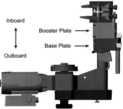
Pro-Cut's current brake lathe, seen in Figure 1-1, bolts to the car's rotor via a hub adaptor; the hub adaptor is not shown. Various size hub adaptors allow the brake lathe to be mounted to most foreign and domestic vehicles.
The cutting head's inboard-outboard placement relative to the vehicle (see Figure 2-5), is adjusted so as to roughly center the rotor between the cutting tips. This placement is accomplished by bolting the cutting head to either a "booster plate" for inboard placement, or to a "base plate" for outboard placement depending on the rotor's position within the wheel well. The technician brings the cutters into contact
with the rotor and then adjusts the dials at the back of the cutting head to set the
depth of cut. Feed is engaged to start the cutting process and these steps are repeated as needed.
1.3
Design Requirements
Many requirements restrict cutting head design options. A list follows
" New cutting head production cost is to be under $300. Production cost is the
cost per machine in quantities of 2,000 units per year.
" No more than one sensor for depth of cut is allowed. Due to possible patent
infringement, multiple depth of cut sensors are disallowed.
" The new cutting head must cut rotor thicknesses ranging from 2 mm (0.079 in)
to 63.5 mm (2.5 in). Rotor thickness is the distance between the two braking surfaces.
Cutting Envelope
Figure 1-2: The cutting envelope is the hatched rectangle
* The system must determine rotor thickness before and after resurfacing and
accordingly set the depth of cut.
* In case of controller failure, the machine must be operable in manual mode.
* The machine must measure lateral run-out non-intrusively. That is, it must
determine rotor thickness variation without altering the freshly cut surface.
* The new cutting head must fit inside the wheel-well of various cars. Wheel-well
rotor placement varies from automobile to automobile. Therefore, cutting head
placement must encompass a broad range in order to meet this criterion. The
cutting envelope is indicated by the hatched rectangle in Figure 1-2.
Chapter 2
Machine Design
2.1
Design Approach
A discussion of machine design and implementation follows. Bearing design, motor
sizing, actuator selection, experimental results, interesting machine elements and de-signs are outlined in hopes of benefitting future machine dede-signs of the reader and
the writer.
2.1.1
Rotary vs. Linear
Rotary and linear cutting tip arrangements are the most obvious design solutions,
shown in Figures 2-1 and 2-2.
Rotary
The rotary design appears to be the most simple to design and manufacture. A rotary encoder measures differential motion between cutting tips and a clutch mechanism
switches actuator torque from one cutting tip to another so that only one motor is
needed. The limitation of moving a single cutter at a time is moot: only differential motion can be measured according to design specifications, therefore only one cutter may move at a time for any design. We have a common pivot point and a single bearing set; therefore a minimal number of precision parts are needed. In addition,
Figure 2-1: Rotary cutting head design
the rotary bearing is inherently easy to seal.
A rotary design is somewhat complicated to control. Abbe errors, although math-ematically compensatable, can cause large errors because the cutting arms act like lever arms by amplifying angular errors. A very high-resolution encoder is therefore needed to accurately set depth of cut.
For example, if we specify the depth of cut to be 0.02" and let the rotor be placed symmetrically between the two cutting arms as they come into contact with the rotor surface. The arm length must be roughly 3" to cut the entire braking-surface radius. Depth of cut and arm rotation are related as follows
LsinO = C (2.1)
where C is the depth of cut, L is the arm length and 9 is the cutting arm rotation. With C = 0.02", and L = 3", the cutting arm must rotate 0.382 . A typical encoder has 2000 counts per revolution, which equates to 5.5 counts per degree or 0.18 degrees per count. It is feasible to move the system 2 or 3 counts, but cutting arm placement will not be robust to disturbances. For the case when the cutting arms
Figure 2-2: Linear Cutting Head Design
encoder, it becomes impossible to set depth of cut to the required accuracy.
To maintain rotor thickness variation less than 0.0005", each cutting tip must be
held stationary to within ±0.00025", equivalently, the arm must not rotate more than
±0.0048
.
A 2000 count per revolution encoder cannot detect such motions, i.e., this
system tries to hold position to
14oof an encoder count. However, an anti-backlash
worm-gear reduction easily allows the system to meet the criteria and is a simple
solution.
For example, holding the cutting arms to within 15 counts requires a 570:1 gear
reduction between the encoder and the cutting arms. Either a single 570:1 worm-gear
reduction or two 24:1 worm-gear reductions placed in series would allow the system
to meet the requirements.
In fact, the performance specification is easy to meet: we require only that the
tools be stationary to within 0.0005", but this is achievable with a lower resolution if
the system does not backdrive.
Linear
A simple linear-motion design is shown in Figure 2-2. Two motors, one for each cutting arm, rotate fine lead screws which transmit torque to the cutting arms via preloaded nuts. Multiple bearing surfaces means more precision parts and higher cost which are major drawbacks. The high resolution and zero backlash of preloaded fine lead screw mechanisms, allow for an inexpensive standard resolution encoder.
Although the linear system's mechanical part costs are higher than the rotary system's, ease of cutting tip placement and regulation afforded by the kinematics of the linear design's simplicity outweigh the rotary system's low cost advantage. Therefore, the new cutting head implements a linear arrangement.
2.1.2
Motor Type Selection
DC motors and stepper motors are the most reasonable lead screw actuators based
on the design constraints. Pneumatics or hydraulics were ruled out by the sponsor.
Stepper motors are extremely simple to control, relatively inexpensive, have a long life and are open loop stable. Their main drawbacks are very low stall torque and that large gear reductions are needed for smooth motions. Constant depth of cut is imperative; accordingly the system cannot be back drivable. A lockdown mechanism should be used in conjunction with a stepper motor drive.
In comparison, DC motors are relatively complicated to control, are open loop unstable, and on average cost slightly more than an equivalent stepper motor. DC motors have smooth motions and generate high torque output. They easily prevent the lead screws from being back-driven so a lockdown mechanism is not needed.
Both motor types have advantages and disadvantages. In summary, the system is either driven by a less expensive stepper motor with gear reduction accompanied by a lockdown mechanism for regulation, or a DC motor that is slightly more complicated to control without a lockdown mechanism. DC motors are chosen because of their
2.1.3
Lead Screw and Motor Sizing
Cutting tip placement requires precision actuation. Worm gear, or small lead lead-screw mechanisms produce the desired cutting tip placement at a reasonable cost. Worm gears are a good solution for specific applications but the backlash associated with meshing gears could be treacherous to cutting tip regulation due to fluctuating loads inherent to lathing. Therefore, a lead screw with a preloaded nut to prevent backlash is the choice actuator.
To regulate the cutting tips to within 0.00025", a fine lead lead screw must be used. Assuming that position can be accurately held to within 15 encoder counts, which equates to ±1.35 motor rotation, the motor shaft rotates no more than 2.7 The desired lead of the lead screw is calculated as follows
rev.
0Ox
xLead(D
(2.2)
36tf
where
6
= rotation of the shaft = 2.7D = distance travelled = 0.00025"
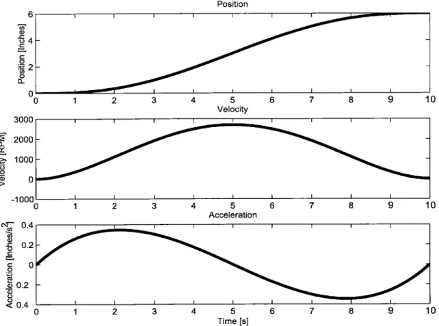
The lead must be less than 0.033"/rev. The project sponsor stipulated that the cutting tips must be at cutting position in under ten seconds. After examining the cutting envelope, it was determined that the maximum cutting tip travel is roughly 6" from maximum inboard to maximum outboard positions. Assuming that the motor will spin at a maximum of 3,000 rpm and that the cutting tip is attached to a lead screw with a lead of 0.025 inches, the tip will travel 6" in 10 seconds as shown in
Position 0 1 2 3 4 5 Velocity 1 2 3 4 5 Acceleration 1 2 3 4 5 Time [s] 6 7 8 9 10 6 7 8 9 10 6 7 8 9 10
Figure 2-3: Cutting tip trajectory: position, velocity and acceleration
C 4.22 -0 0 I I I I | 3UUU 2000 1000 0 1 n
0-cc
6 0 a) I I 1. .I I UU 0 c'" O.4- 0.2-0 0.2 <0.4 0 - I - I -- -III . nrr IThe lead screw must be stiff to ensure that its first mode is not excited as it
rotates at 3,000 rpm. By intuition, the lead screw diameter should be large and its length should be short to increase stiffness. Looking at "off the shelf" lead screw
mechanisms, the largest diameter shafts with 0.025" lead have 1/4" diameter.
The lead screw's first resonant frequency can be approximated using Rayleigh's
method, which may be stated as follows: "In the fundamental mode of an elastic
system, the distribution of vibration and potential energies is such as to make the frequency a minimum," [13]. This approximation is an energy based method and slightly overestimates a systems fundamental frequency; the fundamental frequency is approximated by equating average kinetic energy to the average potential energy and solving for w.
The lead screw's potential energy T is
11 F(
2\T=
2E1}
y)ydx
(2.3)
0
The work done by the external system on the shaft is
2
J\
Y
dx
(2.4)
0
where y is the lateral displacement of the lead screw's axis at a distance x from one
end, 1 is the lead screw's length, EI is its bending stiffness, and P is thrust load from
the external system.
The available kinetic energy is calculated by subtracting Equation 2.4 from Equa-tion 2.3. A shaft element has mass per unit length m/, and a velocity 27rny, where
n is the shaft's angular velocity. The kinetic energy, V, from bending about its axis is
V = 27r22mly2dx (2.5)
Raleigh's Method then gives
217r22m y2dx= 2EI d2y1dx-1pdx
f
dx
22 J
dx)
0 0 0
Introducing non-dimensional variables
A2 - p12
EI
V -47r 2mrn2l4
EI
equation 2.6 may be written
d_2y
(A>
[(dy'
2 4'2d
dx 2 dx+ y2dxI
x) j ]dx}}I
0 0 0(2.6)
(2.7)
(2.8)
(2.9)
Ignoring the lateral stiffness of the nut, we can model the lead-screw mechanism
as a cantilever beam. Therefore we need to come up with a deflection function y (x)
that matches a cantilever beam's boundary conditions. The shaft is clamped at x
=
0
and free at x =1, thus the deflection y and slope L are zero at x = 0. The bending
moment ENIk and shear force El
dx2 dxdyare 3zero at x
=
1. Also, it can easily be seen
7
that EI4 = 0 at x =1.
A deflection function that matches these constraints is
y=2013x2 -101 2x3
+x
5(2.10)
Solving Equation 2.9 for a gives
The lead screw parameters are listed as
= 1.875 = 0.2032 m =2.1 E+011
N/M 2 = 8e-011m
4 =0.005436 m
=7865 kg/m
3 = 0.000023 m2clamped-free end condition
lead screw length
Young's Modulus
-r x d
4/64
shaft diameter
material density
shaft cross-sectional area
The shaft's first mode is well above the 50 Hz excitation caused by rotating the
3,000 rpm motor speed; therefore this system will be stable.
The cutting tip motion needs to be as smooth as possible to reduce the likelihood
of exciting high frequency modes, and to minimize torque requirements. A
5thdegree
polynomial position trajectory allows the user to specify the cutting tip's initial and
final positions, velocities, and accelerations [5]
6(t)
=
ao+
ait+
a 2t 2 + ast3 + a4t + at 5(2.11)
where constraints are specified by constants ao through a5
as
0
o
= aoOf
= ao+
altf+a2tf
+at3+a4tf +
astf 9o =a,
f=
a1+
2a2tf + 3a3t2+
4a4t3 +5ast}
0o = 2a
2
Of
=2a
2+
6a3tf +12a
4t2+ 20ast3
(2.12)
a
1
E
I
d
p
A
We have six equations and six unknowns. The solutions are
ao = 60a
1 =O.
a
2 = 002
2 00 - 2 0 0o
- (86k +120)tf - (350 -ft
a3 = 2t3 f(2.13) 3 0 0o
- 3 00f + (14f
+ 16 0 )tf + (35o - 2f)t
a4 = 2t4f
120f - 1200 - (6Qr
+ 690)tf
- (jo - f)t
a5 = 2tThe position, velocity and acceleration profiles can be seen in Figure 2-3.
The torque required to drive the load is defined as follows
Ttot =Tf +TV+TI+-T
(2.14)
where
Trot = required torque
Tf = nut drag torque
T,= viscous torque
T = load torque
TA = torque to accelerate/decelerate inertia
Viscous torque Tv, is proportional to speed and is defined in Equation 2.15
T = Kd x W (2.15)
Load torque T, is defined in Equation 2.16
T, Load x Lead (-6
27r
xEfficiency
Acceleration torque TJA is defined in Equation 2.17
T9A =J x
A
(2.17)
TJA =
acceleration torque
J
=
effective inertia of the motor shaft, coupling and lead screw
A = acceleration rate
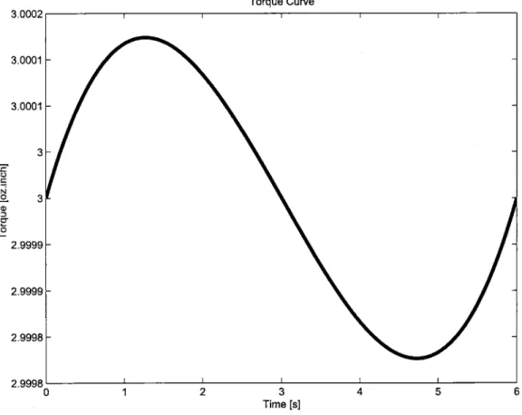
Detailed trajectory and torque calculations can be found in Appendix C; the torque
profile can be seen in Figure 2-4. To properly select a motor, the maximum required
torque is multiplied by a safety factor. The motor's intermittent duty zone should
match this value.
Torque Curve 3.0002 3.0001 -3.0001 - 3--2.3 2.9999- 2.9998-2.9998 0 1 2 3 4 5 6 Time [s]
Inboard
Outboard
Booster Plate
-Base Plate
--Figure 2-5: Inboard-outboard definition
2.1.4
Inboard-Outboard Positioning
Automatic vs. Manual Actuation
To minimize costs, coarse lateral movement (inboard-outboard movement) is
manu-ally set, see Figure 2-5. Although this does not allow for "hands free" lathe operation,
the decision is straightforward. Similar to the setup of a standard CNC lathe, the
machinist manually sets the tailstock, zeroes the machine, and sets depth of cut
pa-rameters in the computer. Likewise for the new brake lathe design the technician
places the cutting tips within an inch of the rotor's surface, zeros the machine, and
commands a depth of cut. This choice greatly reduces costs.
Sliding Contact Bearings
To set depth of cut and adjust inboard-outboard position, a minimum of one linear
bearing system is needed. Cost limitations rule out rolling element bearings, and
low traversal speeds do not require them. Sliding contact bearings are an adequate
choice; they are simple, inexpensive, have high stiffness, and inherent damping. These
properties are well suited to machine tools [12].
The current brake lathe uses dovetail bearings for traversal along the feed direction
(see Figure 2-6), but the project sponsor expressed interest in a gibless bearing system
because vibrations cause the gib to become misadjusted.
Feed
Chapter 3
Kinematic Design
3.1
Exact Constraint Theory
Accuracy, repeatability, and resolution are important measures affecting the quality of a machine. Accuracy is a measure of the maximum error between the average exper-imental value and the desired value. Repeatability is the measure of error between attempts on the same desired output. Resolution is the smallest mechanical step
that the machine can make. For the brake lathe, accuracy is the difference between actual cut depths and desired cut depth, repeatability is the variance of cut depth
between different cut sessions, and resolution is the minimum allowable cut depth. To minimize these quanta, exact-constraint bearing design is implemented. Properly executed, exact constraint bearings have high repeatability and smooth motions (12].
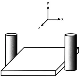
Three-dimensional objects have six degrees of freedom, three translation motions
(referred to as X, Y and Z) and three rotary motions (referred to G0, y and 6 )
as shown in Figure 3-1. These six degrees of freedom fully define the position and orientation of an object in space. When designing a machine, we must account for these six degrees of freedom so that the machine is high performance and low cost. The use of exact constraint design, "kinematic design," uniquely constrains these six degrees of freedom to obtain the desired precise and repeatable trajectory. Such mechanisms do not have "play," binding and assembly stresses, without the cost of
y x zY Dy >x z
Figure 3-1: Six degrees of freedom
Overconstrained designs result when imposed constraints compete to control the same degree of freedom. These systems have three potential problems [2]
" Loose fit. That is, the dimensions of the bearings are such that there is "play"
between the parts.
* Tight fit. The dimensions of the bearings are such that there is interference between the bearings and they bind against each other.
* Tolerance specification. To fix dimension problems, bearing tolerances can be tightened with a manufacturing cost penalty.
Overconstrained design by mating two perfectly dimensioned parts still results in built up stresses. For example, a doubly constrained plate in the x-direction as shown in Figure 3-2, generates internal stresses as temperature variations or external forces cause plate dimensions to vary. Thus it is better to avoid an overconstrained design
to avoid internal stress buildup.
Use of nesting forces avoids overconstrained designs. Nesting forces are used to constrain a degree of freedom, therefore each constrained degree of freedom must have a nesting force and a contact point. Nesting forces are adjustable forces that preload the part against a hard constraint. Machine screws, flexures and balls in
y
x
z
Figure 3-2: Overconstrained plate
Taking the example of the plate from Figure 3-2, by replacing one constraint
with a flexure the object will be exactly constrained in the x-direction. As part
dimensions change, the flexure deflects and does not damage the plate as would a
hard restraint [11].
Flexures are higher performance elements than other constraint devices. Their
simplicity is elegant; self-adjusting force application and zero friction are ideal nesting
force mechanism properties. Drawbacks are that flexure element size is orders of
magnitude larger than the displacement, and they need to be designed for maximum
and minimum loading conditions [2].
3.2
Bearing Replication
Bearing replication is an inexpensive alternative to precision bearing manufacturing.
It improves system accuracy and repeatability, simplifies manufacturing and assembly,
and extends equipment life. It also replaces metal-to-metal bearings to reduce the
coefficient of friction.
By making a mold of a high-precision part, a high-precision mating surface is
created. This is the basis of bearing replication. Various bearing replicant-materials
contain teflon, steel or aluminum fillers, depending on stiffness and friction require-ments. The bearing replicant-material also comes in putty form, a no drip solution for overhead and vertical surfaces, and an injectable form to fill pockets.
An abbreviated description of the replication process is as follows
* A high-precision master part is machined to provide the molding surface. It is preferred to have a ground surface finish as any errors will be duplicated in the replication process. This part is coated with a release agent, usually a spray wax, that provides final bearing clearance.
* Sandblasting a loosely toleranced part provides a large adhesion surface area.
" The adhesion surface part and molding surface part are placed in a fixture
so that the bearing surfaces are properly aligned. Bearing replicant is then injected/poured between the mating parts and allowed to cure.
Minimizing the amount of bearing replicant maintains bearing stiffness and avoids polymerization thermal affects (part deformation). A typical compressive modulus of elasticity, according to (ASTM D-695) (1/2" Cube) value is 60,000 kg/cm3 or 8.5 x 10 5 psi.
Putty bearing replicant was initially tried on prototype 1 but it was difficult to apply due. to poor machine-assembly design, the putty was squeezed out while assembling the machine. Designing an injectable bearing replication system for both prototypes is quite feasible and should be implemented in future work.
More information on replicants can be found from Devitt Machinery Company [3] and Philadelphia Resins [10].
Chapter 4
Prototype 1
4.1
Exact Constraint Theory Applied
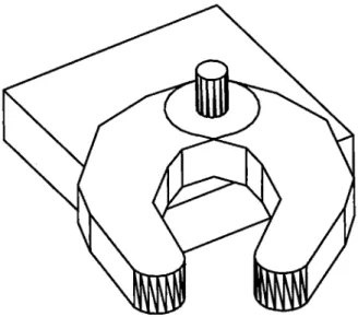
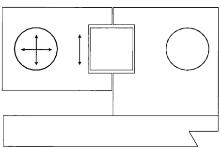
The kinematic bearing system shown in Figure 4-1 eliminates five degrees of freedom as only inboard-outboard motion is needed. A side view of the cutting head,
per-pendicular to the inboard-outboard direction (see Figure 4-2), shows the round-shaft bearing constraining vertical and horizontal motion. The rectangular-shaft bearing
constrains rotation about the round bearing, therefore three degrees-of-freedom are constrained.
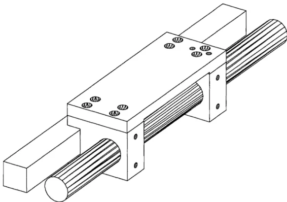
To prevent the linear bearing system from yawing or pitching, the bearing-pad
spacing-ratio should be 2:1 or higher, length to width. Length is along the direction
of motion [12]. To achieve this ratio, a split-bearing "catamaran" configuration is employed as shown in Figure 4-3. Each bearing pad has a 1:1 minimum surface area,
length to width. They are spaced 3:1, length to width. This exactly constrains two rotational degrees-of-freedom, leaving only inboard-outboard motion free.
Although placing a round shaft through a hole overconstrains the round shaft bearing, it is chosen because the shaft parts (bushings and shafting) are "off the
shelf" and can be purchased at low cost in high quantities. Thomson Nyliner bearing pads and Thomson rails comprise the round-shaft bearing system. Production-run manufacturing of the catamaran bracket can be a cost effective extrusion with sec-ondary machining to "clean up" the loose tolerances inherent to the extrusion process
Fi ur.41.Pr to y e :
ss mb y
.f
h f t c
Figure 4-1: Prototype 1: assembly of the first cutting-head prototype
I
Figure 4-2: Prototype 1: side view showing kinematic constraints on catamaran slider
I I
Figure 4-3: Prototype 1: view of catamaran bearing system
(usually ±0.02" per inch along the length of the part).
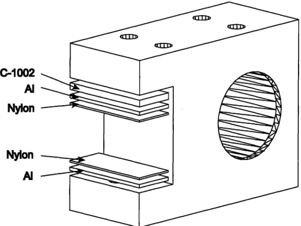
For the rectangular bearing, the catamarans ride on bearing pads made of Nylon sheets 0.015" thick, backed by aluminum shims. Nylon acts as a soft elastic
poly-mer pad that embeds any asperities of the square-bearing shaft or metal particles generated during the lathe operation. Thus it prevents the bearing surface from
be-ing damaged. The aluminum shim provides stiff backbe-ing for the Nylon and provides
proper spacing for 6 lbs minimum preload.
C-1002, a high-performance vibration isolation/damping material by E-A-R [4], is placed between the aluminum shim and the catamaran bearing as shown in Figure
4-4, thus providing bearing preload. The preloaded level was set based on feel; the sliders are movable by hand with some effort, and easily placed via lead screws.
0-1002
A
IN
Nylon
Nylon
4.2
Mockup Testing
4.2.1
Goals
A mockup was built to determine the dynamic response of the machine while cutting and to measure the prototype's surface-finish capabilities. Simulation is a very
pow-erful and useful tool but it is only as good as the model. It is difficult to accurately
model all bearing surface interactions and the cutting forces under our time con-straint. Therefore, a mockup was built because it gives accurate results in a minimal amount of time.
4.2.2
Methods
After bolting the lathe to a rotor, a dial indicator is used to measure the displacement
between the cutting head and the rotor's brake surface (lateral run-out). Screws
between the brake lathe and hub compensate for misalignment, which are adjusted so
that lateral run-out is less than 0.003". This ensures alignment between the cutters'
feed direction and the rotor's surface.
The rotor is rotated to cutting speed and the cutting tips are moved into cutting
position. A micrometer measures rotor thickness before and after cutting and their
values are subtracted and divided in half to estimate each side's depth of cut.
A tri-axial accelerometer, PCB corporation model number 356B08 [8], is mounted
to the inboard cutting tip and the power spectrum is collected. Also, modal tests
are performed to match the mode-shapes' frequencies to the power-spectrum-data frequencies. Due to the lack of fixtures, the lathe is tested in the outboard position only. This is not the ideal testing situation because the lathe is "retracted" and is more "stiff" than in the fully inboard position, and it is best to test the system in the "worst case scenario" to determine its full capabilities.
4.2.3
Results
Based on visual inspection, light-cut lathe operations produce a smoother and a more
non-directional surface finish than the current cutting head. A profilometer measures
smoothness of 50 p-inches on average, where the manual cutting head outputs
75-80 p-inches on average. A light cut is defined as a depth of cut less than .007" on
each side.
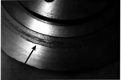
Depth of cut greater than .00T' on each side causes the system to vibrate wildly.
By visual inspection, chattering cutting tips produce an extremely rough surface finish
as shown in Figure 4-5. The patterned surface finish indicates that the cutting tips
are moving periodically; i.e., the system is excited at a resonant mode. It is not
clear, based solely on the power spectrum data as shown in Figure 4-6, which mode is
being excited at 150 Hz but it is certain that the mode comes from either the bearing
shafts bending or play between the catamaran bearings and the round shafts. The
catamaran bearings are not preloaded on the round shafts and we believe this is the
culprit.
Figure 4-5: Prototype 1: output rotor finish, chatter highly visible as indicated by
the arrow
differential motion between the catamaran bearing and the shaft bearings, indicating
that the bearing pads are adequately preloaded. An extra bearing with significant
preload is added in an attempt to reduce the vibration problem. Comparing the
power spectra of the light and deep cuts for the system without the extra bearing
and the system with an extra bearing (Figures 4-6 and 4-7), it is clear that the system
still has a resonance at 150 Hz. The extra bearing pad does not solve the problem.
x -CD on " N
Light cut, grey = without extra bearing, black = with extra bearing -150 --200 -.-.-.-..-.-.-. -250 -. -..-..-. -300k 10 10 102 1 Frequency [Hz] -150 -200 - -.--..- -. -250 . - - - --3000 104 10 10 102 1 Frequency [Hz] -150.! -200 250 -1041 100 10 1 Frequency [Hz] 102
Figure 4-6: Prototype 1: light cut power spectrum data from outboard cutting tip.
X-direction is the inboard-outboard direction, Y-direction is the feed direction and
the Z-direction is along the vertical plane
03
3"
Deep cut, grey without extra bearing, black = with extra bearing -100 -- , , I---150 - - - - - - -- -- - - - ---CO E -200
:1
-250 10~ 10 10 2 103 Frequency [Hz] -100 -1 5 0 . .. ...... .... . ... ... .... .. . .. . ... C S -200 ... -250---300 1 0 2 10 10 10 10 10 Frequency [Hz] . .. ... ... ... ... .. ... . . . .... . ... . 7 ' -15 0 - - - -- -- - -- -- - - -- --200 - ---. -. --. -.-.--N -250 - -10~110010 i02 103 Frequency [Hz]I
I
I
I
/
A
A
A
A
A
ZJ--Figure 4-8: Prototype 1: first bending mode. The system bends about the X-axis.
The gray line represents the deformed system and the black line represents the
unde-formed system
4.2.4
Conclusions
The floating bearing design with two round shafts and one square shaft is far too
compliant for this application. Fluctuating cutting forces excite the cutting head at
its resonant frequency and cause chatter; an investigation of stiffer inboard-outboard
bearing designs is needed.
Chapter 5
Prototype 2
5.1
Goals
The main stumbling block in developing an on-car brake lathe that meets the length-of-travel requirements is designing a linear motion system that travels the cutting
envelope range, yet is inexpensive and "stiff enough." We consider three approaches
to the design and manufacture of the linear bearings: (1) bolt together "off-the-shelf"
modular linear bearing slides, (2) design an extrusion and tighten tolerances with a secondary machining process, or (3) design an extrusion with a flexure that preloads the bearings and allows for loose tolerances of extruded parts.
The use of modular linear bearings is a quick and easy solution. In this design we "piggy back" two slides, thus achieving the range of travel depicted in Figure 1-2.
The bottom slide bolts to the feed mechanism on the brake lathe while a plate-with
cutting tips and a fine-linear motion system-bolts to the back-side of the first slide.
The disadvantage is high cost. A size-35 linear ball bearing slide with 12" travel costs
$435. Two of these are needed, putting the price at $870. This puts the project well over budget and therefore is not a viable option.
An aluminum extrusion along with a secondary machining operation to tighten the tolerances is a less expensive approach. Aluminum extrusions cost roughly $1 per pound, which is equivalent to $5 per inboard-outboard bearing. The use of a grinding process to tighten up tolerances would increase the price to roughly $75 per
inboard-outboard slide system. While not overly inexpensive, this design can be made
"stiff enough" by carefully designing the slide geometry. An extrusion with a built-in
flexure to account for loose tolerances is risky, but would result in a lucrative cost
reduction. This idea is discussed in Chapter 6, but because of time constraints, we
decided to take the middle road and design an extrusion with a secondary grinding
operation to obtain the desired tolerances on the linear slide.
5.2
Description of Redesign
The second prototype's assembly and exploded drawings can be seen in Figures 5-1
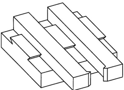
and 5-2 respectively. The new inboard-outboard bearing is redesigned as an oddly
shaped beam where the sliders are kinematically constrained as shown in Figure 5-3.
The kinematic constraints are similar to the first prototype's constraints; the sliders
are constrained in the vertical direction by sides 1 and 3 and constrained in the feed
direction by sides 2 and 4. Constraining sides 5 and 6 prevents rotation about the front
bearing. Making each bearing a catamaran-style bearing system constrains the other
two rotational degrees of freedom as previously discussed. Coarse inboard-outboard
motion need not be highly repeatable or accurate, thus the inboard-outboard bearing
is comprised of a loosely toleranced dovetail. The inboard-outboard bearing beam
has a large thickness to stiffen it in the vertical direction.
- '
.
-
-
Slider
Lead Screw
-
.'Nut
.'
Endcap
Inboard-Outboard
Base
Linear Bearing
Cutter
Figure 5-2: Prototype 2: exploded view
6
0
Figure 5-3: Prototype 2: side view showing kinematically constrained catamaran
bearing
5.3
Results
Preliminary cutting tests show poor results. The rotor's surface finish has a pattern
due to cutting tip chatter, see Figure 5. Modal data from the catamarans (Figure
5-6), was difficult to process due to several modes in the 140 Hz frequency range. Power
spectrum data from the outboard cutting tip can be seen as the black line in Figure
5-4. The peak response at 140 Hz concurs with the modal data.
The use of C-1002 damping material to preload the bearings on this system is
difficult because lubricant from the linear bearings in conjunction with vibration cause
the pads to creep out. Therefore the C-1002 was removed and aluminum-backed Nylon
pads are preloaded via setscrews. This allows for more accurate bearing preload and
is easier to adjust.
Inboard-cutter power spectrum data can be seen in Figure 5-8. The black line
represents the C-1002-preloaded system and the gray line represents the
setscrew-preloaded system. The setscrew-setscrew-preloaded system slightly shifts the resonant
fre-quency from 140 Hz to 150 Hz, but the overall magnitudes and general machine
behavior are the same.
Power Spectrum Data: Prototype 2, Black = C1002 preload, Gray = setscrew preload -1 nn. I II I W -150 -200 10' 100 10 10210 Frequency [Hz] 1 .
-l
S -150 - ---IE-200 10 100 10 1 10 Frequency [Hz] .1 0 0 . .1 .1.p... . . . , . . . r -150-N 1041 100 101 Frequency [Hz] 102Figure 5-4: Prototype 2: power spectrum of outboard cutter comparing C-1002 preload to setscrew preload. X-direction is in the inboard-outboard direction. Y-direction is in the feed Y-direction. Z-Y-direction is in the vertical plane.
- -I-I-I - --.. .-. .. .-. .-- .--.. . -7 vn , I I I I I I I II I I I I I I I I I I I I I 1 1 .1 1 1 11 a I I I I -250' - I t t t - -- - -- - ---. - -. --. --. -. -. -. --.- -.- -. - ...- . .- ..-.. .-. .-. . . -. . .-. -. . .-. -. . . .- -
-.1 ii
Figure 5-5: Prototype 2: chatter output surface finish, 0.015" depth of cut on each
side
Adding a stiffener plate as shown in Figure 5-7 to the inboard catamaran bearing
dramatically improves rotor surface finish and reduces chatter as shown in Figure
5-9. Power spectrum data comparing the C-1002-preloaded system to the
setscrew-preloaded catamaran-stiffened system shows that stiffening the catamaran plate
dra-matically reduces the magnitude at resonant frequency (see Figure 5-8).
CatafmnMlae
Catamaran Slider
Figure 5-6: Prototype 2: view of catamaran bearing system
Power Spectrum Data: Prototype 2, Black = C1002 preload, Gray = setscrew preload with stiffener plate _inn.I. -150 E -200 -250 -Ou, I 10 100 10 102 10 Frequency [Hz] 1 ; .. . F . . . . . F -200k-. -.-. -. -250 10 100 101 102 10 Frequency [Hz] .. inI F I II I -150 .- ...- ..- .. E, -200--250
sk
-100 101 Frequency [Hz] -1 10 102Figure 5-8: Prototype 2: power spectrum; setscrew preload with stiffener plate com-pared to C-1002 preload F-H.-.- -I F . I I I I A . . . 10 - -- - - - - ---- -- --- --- - --- - - --- - ... ...- .-- ---- --- --- ..-.- . .- .- -- - - - --- -- --- -- -- -- .- .- .--- - -- . . .- . . -- - - -- - - -- . .
.-Figure 5-9: Prototype 2: output 50 M-inch surface finish at 0.010" depth of cut per
side
Figure 5-10: Prototype 2: view showing added stiffener plates
To increase the catamarans' stiffness two more stiffening plates were added (see
Figure 5-10). The power spectrum at the inboard cutting tip in this new configuration
can be seen in Figure 5-11. The rotor's surface finish is measured as 70-80 u-inch
at a 0.015" depth of cut per side (see Figure 5.3). The 70-80 p-inch surface finish is
acceptable, but a slight chatter pattern forms.
Power Spectrum Data: Prototype 2, Black = C1002 preload, Gray = setscrew preload with multiple stiffener plates > 00[... . .. ... I-. -100 1 -150 --- -x-300[:I 101 100 101 102 103 Frequency [Hz] -150 1 10 10-io -200...--- - -- - Fr-eq-u--e-nc. [ ] --250
F
-300FI 10- 100 101 102 103 Frequency [Hz] -100 -- , ,- , -- , , -- r - 1 5 0 - - -- --- - -. --.-. .-- .-.-.-.-. .-.-.-.-10- 10 0 101 10 2 10 3 - Frequency [Hz]Figure 5-11: Prototype 2: power spectrum; setscrew preload with multiple stiffener plates to C-1002 preloaded system
Figure 5-12: Prototype 2: output 70 p-inch surface finish at 0.015" depth of cut per
side
Resonances occur at 60 Hz, 135 Hz, 150 Hz and 225 Hz as can be seen from the power spectrum data shown in Figure 5-11. The mode shapes at these frequencies must be determined in order to "stiffen" the structure at those resonances.
Numerous unsuccessful modal data collection attempts revealed that the test stand
has several modes in the frequency range of interest. These mask the cutting head dynamics, making cutting head modal analysis difficult. To eliminate the unwanted test-stand dynamics, the brake lathe was suspended by surgical tubing. The brake lathe is roughly 100 lbs and the surgical tubing acts as a very light spring, thus any
resonances due to the suspension will be less than 2 Hz, well below the frequency range of interest.
For the suspended brake-lathe setup, the first mode is at 118 Hz and its mode shape is shown in Figure 13. Therefore we conclude that the 60 Hz spike in Figure
5-11 is most likely an artifact of the AC current supplied to the motor. The 5-118 Hz
mode appears to be primarily rigid body rotation about the y-axis, but it is physically impossible for this to happen; as previously stated, all rigid body modes are less than 2 Hz. Thus another part of the machine, such as the brake lathe's motor interface, must have strain energy developing. It is not likely that this mode is the source of chatter because it is far enough below 135 Hz.
The second mode, at 143 Hz, can be seen in Figure 5-14. This top-down view shows differential motion between the entire cutting head assembly and the brake lathe. The linear bearings and catamarans are rotating about the z-axis slightly
more than the gear box. The third mode, at 161 Hz, can be seen in Figure 5-15. Again, this front view shows differential motion between the cutting head assembly and the brake lathe about the x-axis. The fourth mode, at 177 Hz, can be seen in Figure 5-16. This mode shape is very similar to the third mode in that the cutting
head is deflecting about the x-axis with respect to the gear box. The gear box also deflects in this case.
Catamaran
Linear . Plates
Bearings
Inboard-Outboard
Feed Dovetail Bearing
z
Feed Gear Box
<
z
'Y
z
z
Figure 5-13: Prototype 2: first mode at 118 Hz. The grey lines are the deflected
cutting head, the black lines are the un-deflected cutting head.
C_
Y
IV
Y
x
I
V
TY
x
Y
x
I
V
Y
z
LI
V
-'
Z
YFigure 5-15: Prototype 2: third mode at 161 Hz. Front view. The grey lines are the
deflected cutting head, the black lines are the un-deflected cutting head.
- - -
-z
Y
z
Y
z
Y
S--z
Y-"
111 7r
5.4
Conclusions
The new cutting head with the stiffener plates is extremely stiff, and meets the cutting
specifications. However, the feed dovetail bearing is now the most compliant element
of the machine and therefore is the source of slight pattern that occurs at full depth
of cut. Therefore to improve this design, (1) the cutting head should be lightened,
(2) the catamarans should be stiffened and damped, and (3) the feed dovetail should
be stiffened to improve this design.
Chapter 6
Non-Linear Flexure Design
6.1
Desired Characteristics
An extrusion process yields loosely toleranced parts; the tightest being +0.010 " per foot on the specified dimension along the length of the part. For example, an extruded 1" square profile may have profile dimensions 1.010" or 0.990" at the opposite end if it is 1' long.
For a preloaded linear bearing with stiff bearing pads, 0.020" tolerance is
imprac-tical. To maintain bearing pad contact, bearing preload must exceed the sum of the tolerance dimensions of the two mating parts. Specifically, the opposing bearing pads must be preloaded 0.040" to account for the 0.020" variance of dimensions on the
slide and the catamarans. This ensures bearing contact along the entire length of
bearing and preserves stiffness afforded by full contact of the bearing pad. A light
preload is desired in order to maintain low friction and low torque requirements from the actuator. Therefore preload force should be between six and ten pounds.
Using the specifications above, and assuming that elements in the preload path have a linear stiffness k, it is found that k must be 50 lbs/in. The initial preload must
be 0.12" and the maximum displacement is 0.2", which is very large and is difficult
to design for with our size constraints. Thus a regressive preload device is needed, i.e., one in which the nesting force dies out as displacement increases.