READ THESE TERMS AND CONDITIONS CAREFULLY BEFORE USING THIS WEBSITE. https://nrc-publications.canada.ca/eng/copyright
Vous avez des questions? Nous pouvons vous aider. Pour communiquer directement avec un auteur, consultez la
première page de la revue dans laquelle son article a été publié afin de trouver ses coordonnées. Si vous n’arrivez pas à les repérer, communiquez avec nous à PublicationsArchive-ArchivesPublications@nrc-cnrc.gc.ca.
Questions? Contact the NRC Publications Archive team at
PublicationsArchive-ArchivesPublications@nrc-cnrc.gc.ca. If you wish to email the authors directly, please see the first page of the publication for their contact information.
Archives des publications du CNRC
This publication could be one of several versions: author’s original, accepted manuscript or the publisher’s version. / La version de cette publication peut être l’une des suivantes : la version prépublication de l’auteur, la version acceptée du manuscrit ou la version de l’éditeur.
Access and use of this website and the material on it are subject to the Terms and Conditions set forth at
Pressure equalization and the control of rainwater penetration
Poirier, G. F.; Brown, W. C.; Baskaran, B. A.
https://publications-cnrc.canada.ca/fra/droits
L’accès à ce site Web et l’utilisation de son contenu sont assujettis aux conditions présentées dans le site LISEZ CES CONDITIONS ATTENTIVEMENT AVANT D’UTILISER CE SITE WEB.
NRC Publications Record / Notice d'Archives des publications de CNRC: https://nrc-publications.canada.ca/eng/view/object/?id=6a8be53e-cfb7-489c-9577-bfc4d56af2b4 https://publications-cnrc.canada.ca/fra/voir/objet/?id=6a8be53e-cfb7-489c-9577-bfc4d56af2b4
http://www.nrc-cnrc.gc.ca/irc
Pre ssure e qua liza t ion a nd t he c ont rol of ra inw a t e r pe ne t ra t ion
N R C C - 3 3 1 1 2
P o i r i e r , G . F . ; B r o w n , W . C . ; B a s k a r a n , B . A .
M a r c h 1 9 9 2
A version of this document is published in / Une version de ce document se trouve dans:
Proceedings, Sixth Conference on Building Science and Technology, Toronto,
Ont. Canada, March 5, 1992, pp. 45-65, 1992
The material in this document is covered by the provisions of the Copyright Act, by Canadian laws, policies, regulations and international agreements. Such provisions serve to identify the information source and, in specific instances, to prohibit reproduction of materials without written permission. For more information visit http://laws.justice.gc.ca/en/showtdm/cs/C-42
Les renseignements dans ce document sont protégés par la Loi sur le droit d'auteur, par les lois, les politiques et les règlements du Canada et des accords internationaux. Ces dispositions permettent d'identifier la source de l'information et, dans certains cas, d'interdire la copie de documents sans permission écrite. Pour obtenir de plus amples renseignements : http://lois.justice.gc.ca/fr/showtdm/cs/C-42
46
PRESSURE EQUALIZATION
AND THE CONTROL OF RAINWATER PENETRATION
G.F. Pamer, W.C. Brown and A. Baskaran
INTRODUCTION
The rainscreen concept was first referenced as a means of rain penetration control in the 1940's. Later researchers applied physics principles to develop the 'pressure equalized rainscreen principle' as it is known today. Through the development process a selection of terminology has been used to describe the concept which uses a rainscreen to control rain penetration due to the kinetic energy of raindrops. 'Cavity wall', 'open rainscreen wall', 'rainscreen principle' and 'two stage weather tightness' are key words commonly encountered in literature addressing the control of rain penetration. In most cases, the concepts also addressed the control of rain penetration by other forces such as gravity, surface tension and capillarity. Some specifically addressed the control of rain penetration by wind induced air pressure difference across the wall system. The fundamental differences between these wall concepts are never clearly described. Consequently, when the rainscreen concept is applied to wall design, these key words are used interchangeably and it is difficult to know whatisreally meant when a wall is required to be designed according
to, for example, the 'rainscreen principle'.
A wall system designed according to the 'pressure equalized rainscreen principle' is a wall that is designed to control all the forces that can drive rainwater through its fabric. This means the wall system contains features to control water transport through its fabric due to the kinetic energy of the raindrops, surface tension, gravity, capillarity and wind induced air pressure __ differences. The latter is 11 significant force that drives rainwater into walls. The pressure equalized rainscreen principle was develop to specifically address this driving force. The principle requires that the wall system be designed so that the pressure difference across the exterior cladding, or rainscreen, is nearly zero at all times. This also has the effect of reducing the wind load on the cladding. The control ofairflow is also inherent in the principle. If the air flow through and within the fabric of the wall is not controlled, theairpressure difference across the rainscreen cannot be equalized. Even with the best design concept and construction practices there is always a possibility that water will find its way within the fabric of a wall system. This reality is also addressed by the principle. The wall system has to contain features that will drain to the outside water that finds its way inside the fabric of the wall.
Compartments
Theairpressure inducedbywind varies over the height and width of the building. Itcan be fairly uniform near the center of walls but steep gradients can develop towards the corners A recent literature review conducted by· the Institute for Research in. Constmction has shown that current design gUidelines are not at all comprehensive. Designers are still faced with trying to design a pressure equalized rainscreen wall system without adequate guidelines and tools. EXisting guidelines are mainly qualitative and were established from limited experience. In fact the perfonnance requirements of a pressure equalized rainscreen wall system are still not well understood. Consequently, IRClNRCC has initiated a research project to develop design guidelines for pressure equalized rainscreen walls through modelling, experimental studies and interaction with industry.
PRESSURE EQUALIZED RAINSCREEN WALLS
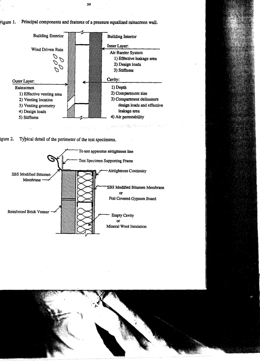
In its simplest fonn. a pressure equalized rainscreen wall system is a double layered wall with a cavity separating the two layers. The cavity is vented and drained to the outside through openings in the outer layer or rainscreen. Sufficient ventingisrequired in the rainscreen so that the cavity pressure can eqUalize qUickly to the exterior pressure. Each component of a pressure equalized rainscreen wall has a number features which need to be designed in order to achieve pressure equalization under most dynamic wind conditions. The principal components of the wall and the features that will dictate pressure equalization perfonnance are listed in Figure 1.
To obtain pressure equalization across the rainscreen. the;air,fl0\Y..through the wall system and the lateral air flow within the wall cavity must also be controlled. This implies that the wall system must contain
• an effectiveair ba"ier systemwithin the inner layer. • compartmentswithin the cavity.
• appropriateventingin the rainscreen. Air Barrier System
The wall system must contain a continuous plane of airtightness that controls air flow through the wall. The plane of airtightness must be made of structural elements or 1)e supported by structural elements capable of resisting the static loads induced by mechanical ventilation and stack effect and the dynamic loads induced by wind. The plane of airtightness and its structural elements are referred to as theairbarrier system. Itmustbedesigned within the inner layer so that the air pressure loads induced on it are transferredtothe structure of the building. It also can be argued that the air barrier system must be rigid to minimize material fatigue, especially at the points of attachment to the structure.
48
and the roof line. This spatial variation in pressure can induce lateralairflow within the cavity unless the cavity is interrupted at suitable intervals. The frequency of these interruptions or cavity comparunents should be such that the variation ofairpressure outside any comparunent is at an acceptable minimum. This means that the size of the comparunents could vary over the face of the wali with larger comparunents at the center of the wall and relatively smaller comparunents near the edge of the wall. The cavity must be closed at all comers since wind flowing around the building will produce high pressure differences at these locations. However, at this time only general guidelines are available fOf the size of the compartments and no guidelines are available for the airtightness or strength of the comparunent closures.
Venting
Sufficient venting is required in the rainscreen so that the cavityairpressure can quickly equalize to the outside pressure. The geomeiry and location of the vent holes has to be designed so that enoughaircan flow into and out of the cavity to achieve pressure equalization acroSs the rainscreen in the required time. The effective area of the vent holes has to be sized relative to the leakage of the air barrier system and to the volume of the cavity. Under dynamic wind conditions the stiffness of the rainscreen and air barrier system will affect the volume of the cavity and this has to be taken into account in designing the venting requirements. The venting should be concentrated along one horizontal plane to avoid any pressure difference over the height of the compartment that may induceairflow within the cavity. Vent holes are preferably located at the bottom of the compartment because they can then also be used for drainage. WHAT DO WE KNOW?
The concept of using pressure eqUalization as a means to control rainwater penetration induced by air pressure difference was first introduced in Canada by Garden in 1963. He proposed basic design requirements for a pressure equalized rainscreen wall system through the 'open rainscreen' principle. The design requirements were presented with the following suggested design guidelines:
• The vent holes should be at least 10 mm in diameter to preventformation ofafilm of water over the holes.
o All vent holes should be placed at the same height and thlt)' should preferably be placed at
the bottom ofthe compartment.
o The depth ofthe cavity should be at least25mm
• The cavity should contain closures at each corner and at 1.2 m intervals for about6m from the corners andfrom the top. It should also contain closures at the center ofthe wall
Although considered an.expensive approach torainpenetration control, the concept found broad acceptance and was implemented in window and wall designs.
In 1973, Latta reviewed Garden's work and proposed a theory for 'pressure equalization based on flow continuity of an incompressible fluid through sharp edge orifices. Latta's theory suggested that under steady wind conditions a venting area 10 times larger than the leakage area of the air barrier is required to obtain acceptable pressure equalization across the rainscreen.
In the last ten years a number of studies on the performance of pressure equalized rainscreen wall systems have been conducted. Klllip and Cheetham (1984) suggested that a
ventinglleakage ratio of 25:1 to 40:1 was required to achieve pressure equalization across the rainscreen. A number of Canadian organizations have been involved in studies on the subject These include:
• National Research Council of Canada • Canada Mortgage and Housing Corporation • Morrison Hershfield Ltd.
• Rowan, Williams, Davies and Irwin, Ltd. • Concordia University
• UniversnyofWestern Ontario
Kerr (1990) noted in an article on rainscreen walls that 'much more research is necessaryto provide sufficient data for the rational design of rain screen walls'. And recently a comprehensive literature review by Baskaran (1992) confmned that the current design guidelines for pressure equalized rainscreen wall systems are not at all complete.
IRC RESEARCH PROJECT
The Institute for Research in Construction has initiated a research project to establish performance requirements and to develop design guidelines for pressure ・アオセコ・、 rainscreen walls. The project consists of three tasks: modelling, experimental studies and development of design guidelines. The rlI'st two tasks are already in progress. An important element of the project is that the studies are performed under dynamic air pressure loads because pressure equalization must be effective under both static and dynamic conditions.
Task 1: Modelling
A computer model based on incompressible and steady flow equations was developed as the ftrst step in this task. (Baskaran & Brown, 1992) Successful simulations have been performed for various combinations of cavity venting and air leakage conditions. As well, the predicted response to ramp and cyclic external driving pressures has been shown to agree
reasonably well with eXperimental data. The next step is to develop the model to include other design features and to account for random external pressure loading and torbulent flow conditions inside the cavity. Currently effortS are directed to identifying a suitable computational fluid dynamics technique.
Task 2: Experimental Studies
A laboratory procedure is being developed to evaluate the pressure equalization and rain penetration control performance of pressore equalized rainscreen wall systems under both dynamic and static airpressure loads. Itcurrently consists ofairleakage, pressure equalization and water penetration tests. Theairleakage control of the wall system is evaluated by measuring theairflow rate through the test specimen under static pressure difference. Pressure eqUalization performance is evaluated by subjecting the specimen to cyclicairpressore differences and water penetration control is evaluated under both static and cyclicairpressore differences.
A test procedure will be developed to evaluate the pressure equalization performance of wall systems in the field. IRClNRCC has already conducted extensive field monitoring of two buildings with pressure equalized rainscreen wall systems. The data collected from these monitoring programs is on me. The measored pressure equalization performance of the systems will be used in support of the model validation and the measured wind pressure profiles will be considered for use in evaluating wall systems in the laboratory.
Task 3: Design Guidelines
The design guidelines will be developed using the model, after the model has been validated with laboratory and field experimental data. It is intended that the guidelines be developed in collaboration with the design industry since practical experience is required to develop effective design gUidelines.
RECENT
mc
EXPERIMENTAL STUDIESThe laboratory procedure has been used toevaluate the pressure equalization and water penetration control performance of a prefabricated brick veneer wall system. Pressure equalization performance was measured for cases of a flexibleairbarrier system and a rigid air barrier system and for cases ofthe cavity being empty or filled with mineral wool insulation. Data was also measured for various cavity ventinglleakage ratios, i.e., the ratio of the cross sectional areaofthe cavity venting and of the leakage opening in theairbarrier system.
Dynamic Testing Facility
The test procedore was performed using IRClNRCC's Dynamic Testing Facility. The test apparatus is approximately 3 m by 3 m and accepts a 1.5 m by 2.4 m test specimen. (Itis
currently being modified to accept a 2.4 m by 2.4 m specimen.) A sealed 2.4 m diameter piston that forms part of the back wall of the apparatus is fitted with hydraulic and electronic equipment
to drive it back and forth at controlled rates. The displacement of the piston causes pressure in the space between the piston and the test specimen to vary, thus varying the air pressure difference across the specimen. The movement of the piston can be programmed to produce sinusoidal, triangular or square waveforms ofairpressure variations of various frequencies and amplitudes. A secondary blower is used to apply the required steady stateairpressure difference across the test specimen.
Test Procedure Air Leakage Test
The air leakage of the wall system is evaluated by measuring theairflow rate through the test specimen under applied static air pressure differences. Theairflow rate is measured under both positive and negative pressure differences.
Pressure Equalization Test
The pressure equalization performance of the wall system is evaluated by sinusoidally varying theaU:セM pressure difference on the exterior face of the test specimen. The minimum and. . maximum driving air pressure differences are set based on the worst case design wind load condition for the building under study. Sufficient pressure taps are installed within the wall system to record pressure differences that occur across and over the height and width of the test specimen. Theairpressure difference across the specimen is varied at frequencies from 0.1 Hz to 2.0 Hz to simulate gust wind conditions. The frequency spectrum of the wind varies with local wind speed. However. the 0.1 Hz to 2.0 Hz range covers a significant portion of the spectrum. The tests are repeated for various venting conditions to establish the cavity venting required to achieve pressure equalization across the rainscreen.
Water Penetration Test
The rain penetration control performance of the wall system is evaluated by performing a three stage water test on the test specimen. The water testisperformed by spraying a continuous film of water on the exterior face of the test specimen under the following conditions:
i) staticairpressure difference of 500 Pa for 4 hours,
ii) cyclic air pressure difference of 500±167 Pa at a frequency of 0.5 Hz for 1 hour.
iii) cyclicairpressure difference of 500±167 Pa at a frequency of 1.0 Hz for 1 hour.
The specimen is instrumented so that water penetrating through the rainscreen is collected and measured. ASTM E·514Standard Test Method for Water Penetration and Leakage Through Masonry and ASTM E-547 Standard Test Method for Water Penetration of Exterior Windows.
52
Curtain WalL\' and Doors by Cyclic Static Air Pressure Differential were consulted in the development of the test procedure.
Test Specimen
Three test specimens .were evaluated in the test program. All were variations of a basic test specimen that was 1.5 m wide by 2.1 m high and constructed of a 100 mm thick reinforced brick veneer cladding (rainscreen), a 100 mm thick cavity and an airbarrier system (Figure 2). Initially, cavity venting was provided by 10 vent holes of 9 mm diameter that were drilled in the first course of the brick veneer. The amount of venting was varied by plugging some or all of the holes. Inlater tests venting was provided by opening head joints in the fll'St brick course.
Specimens #1 and #2 had a flexible air barrier system consisting of an SBS modified bitumen membrane. The cavity of Specimen #1 was empty whereas that of Specimen#2 was filled with mineral wool insulation batts. Specimen #3 had a rigidairbarrier system consisting of 12 mm, foil-covered gypsum boards. The gypsum boards were sealed along their perimeter and at the joint with aluminum tape. The cavity of Specimen #3 was also filled with mineral wool insulation.
Test Protocol Air Leakage Test
The air flow rate through each of the test specimens was measured for each test configuration at pressure differences upto1000 Pa.
Pressure Equalization Test
Pressure equalization perfonnance of the test specimens was evaluated for the case of an airtightairbarrier system for the following cavity venting configurations.
Specimen Vent Configuration Vent Area (cm2)
#1 10 holes 7.1 #2 5 holes 3.6 10 holes 7.1 #3 3 holes 2.1 5 holes 3.6 10 holes 7.1 2 head joints 12.8 4 head joints 25.4
In addition, Specimen #3 was evaluated for a series of ventinglleakage ratios for the 10 vent holes, for 2 head joints and 4 head joints venting conditions. Eight leakage holes, each
approximately 9 mm diameter. were drilled at the top of the gypsum boardtorepresent defects in theairbarrier system. The amount of leakage was varied by plugging some of the holes and this leakage was used with the three venting conditions to simulate venting/lelikage ratios as follow:
Vent Configuration VentinglLeakage Ratio
3 leakage holes 5 leakage holes 8 leakage holes
10 holes 3.4 2.0 1:2
2 head joints 6.1 3.6 2.2
4 head joints 12.1 7.1 4.5
The test specimens were exposed to an exterior dynamic pressure 'difference. .ilPe' consisting of a steady state component• .ilPem' and a sinusoidal component. A·sin(21tft) that can
be expressed over time. t. as
dPe=dPem+A·sin(2nft)
For most tests the steady state component. dPem.wasset to2kPa and'tI1eampHfudeiA;'wassef" to 1 kPa; the pressure difference, LlPe•varied between 1 kPa and 3 kPa. In addition. Specimen#2 was tested with .ilPem set to 1 kPa and A set to 0.5 kPa. In this case LlPevaried between 0.5 kPa and 1.5 kPa. 1\Il tests were conducted for frequencies.
I,
from 0.1 Hz to 2.0 Hz.The pressure difference generated across the air barrier system, LlPabtcan be expressed as .ilPab
=
.ilPabm+k·A·sin(2n/t-4I)The variable component has an amplitude. k·A. that is a fraction of the exterior pressure difference amplitude and a phase shift.
41.
that represents the time lag between it and the exterior pressure. Values of the amplitude ratio. k. and phase shift,41.
are dependent on such factors as the excitation frequency, cavity volume. cavity venting and air bamer system leakage.The pressure difference across the rainscreen. aPn' at a given time. t,.is the difference between the pressure difference across the specimen, aPe. and, the pressure difference across the
airbarrier system, .ilPab. The steady state component. LlPnm•is dependent on the relativeairflow resislances of the rainscreen and the air barrier system, i.e.• the ratio between venting and leakage openings. It will be zero if the air barrier system is airtight. The amplitude of the variable component is dependent on both the amplitude ratio, k. and the phase shift.
41.
between .ilPe and LlPabo Perfect pressure equalization is represented by k=1 andljI=0; However, unless the system is designed for pressure equalization under all wind conditions, it is probable that the amplitude ratio will not be 1 and/or the phase shift will not be 0 and pressure equalization across the rainscreen will not be achieved.54
Water Penetration Test
The three stage water penetration test was performed on Specimen #3 with theailbarrier system intact and with 10 vent holes. This venting condition was the maximum that had been tested to that time and the tests showed that it generated the best pressure equalization response. Under this venting condition the pressure difference across the brick veneer was less than 50% of the amplitude of the variable exterior pressure difference for frequencies of 0.5 Hz and less. The continuous mm of water was created over the face of the specimen by spraying water at the top of the specimen at a rate of 3.85 Vmin.
Test Results
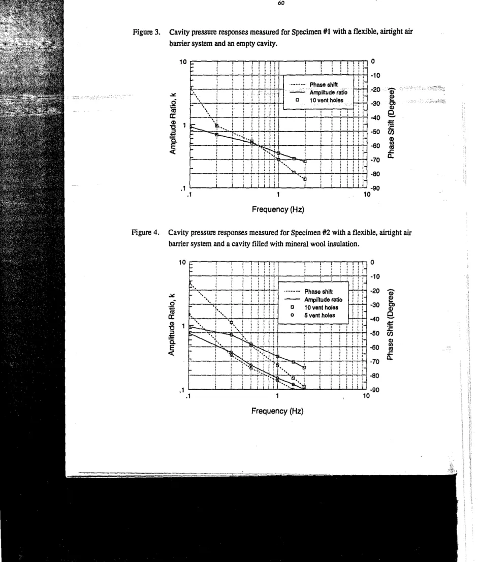
As discussed in Test Protocol, the frequency response of the three test specimens was measured with various combinations of
ait
barrier system (ailtightness and flexibility), cavity (empty and filled), and venting. The cavity pressure response, Le., the pressure difference measured across theail barrier system, for several test configurations of Specimens #1, #2 and #3 are presented in Figures 3 to 7. It must be noted that these responses can only be applied with confidence to the wall system under test. For other systems, they are only indicative of trends since they cannot be extrapolated with confidence to other wall configurations at this time. Some general conclusions that can be drawn from the results are as follows.Effect of the base load
The pressure equalization performance of Specimen#2 was measured for two levels of external pressure to determine if the performance of the wall system was dependent on the magnitude of the external pressure (Figure 8). No significant difference was measured in the frequency response of the cavity pressure when the magnitude of the external pressure was doubled. It seems that the pressure equalization performance of the wall system is more a function of the frequency of the external pressure and of the physical characteristics of the wall system.
Filled and unfilled cavity
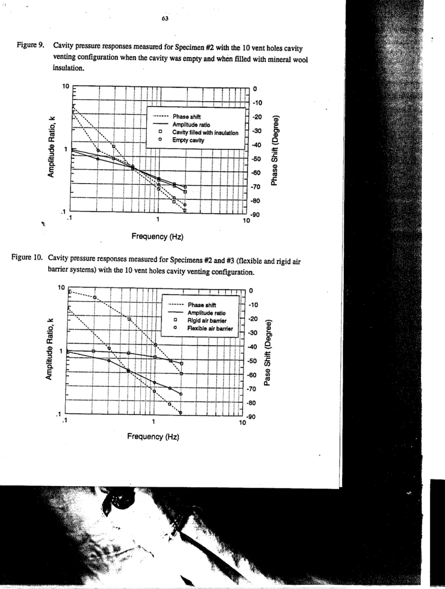
The cavity pressure responses measured for Specimens #1 and #2 were compared to determine the effect on pressure equalization of filling the cavity with a fibrous insulation (Figure 9). The slight differences measured in the amplitude ratio and phase shift can be attributed to measurement error and to the installation of the membranes. Given workmanship limitations, it is practically impossible to install two membranes with exactly the same physical characteristics. The measurements indicate that pressure equalization can still be achieved when the cavity is t111ed with certain types of fibrous material.
Variable cavity volume
The cavity pressure responses measured for Specimens#2and #3 with airtightairbarrier systems and 10 vent holes were compared to determine the effect of a variable cavity volume, in this case the result of a flexible air barrier. on the response of the system (Figure 10). The measurements demonstrated that the cavity pressure responses can be delayed significantly when the elements making the cavity are flexible.
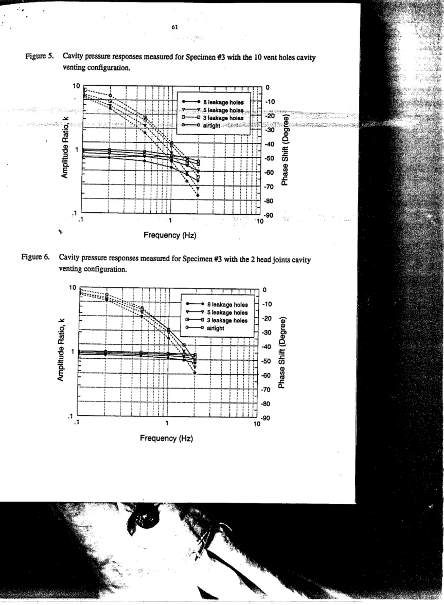
Effect of venting
The cavity pressure responses measured for Specimen#3 with an airtight air barrier system and various venting configurations are compared to determine the effect of venting on the pressure equalization performance of the wall system (Figure 11). The measurements indicate that, as would be anticipated, with too little venting the wall system response is not fast enough to achieve pressure equalization with variable external pressures. However, they also demonstrate that effective pressure equalization canbeachieved with venting that is sized for the physical characteristics of the wall system. - ;- ,_. -_....NᄋBL[セ⦅ᄋL⦅ᄋNMカセB ,"'" 0 • •" " , " " ,__'," _ .C o . "
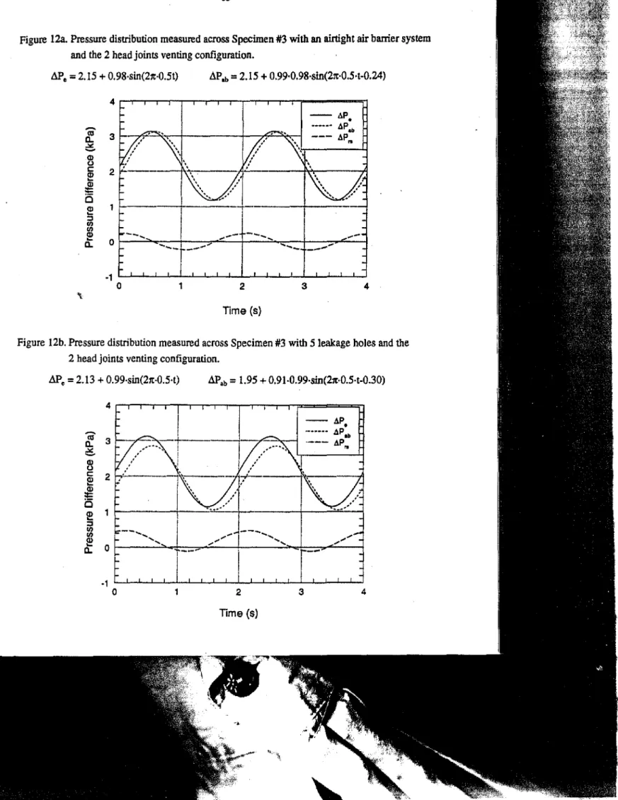
Effect of air leakage
For a wall with an airtightairbaIrier system, the steady state pressure difference across '\
the wall is taken entirely by theairbaIrier system, i.e., .1PIbmis equal to.1Pem' IftheairbaIrier
system is not airtight. a portion of the steady state component of the external pressure difference will appear across the rainscreen. The cavity pressure responses measured for Specimen #3 with 2 head joint venting and airtight and leaky air barrier systems (Figures 12a and 12b) are compared to determine the effect of a leaky air barrier system on the pressure equalization performance of the wall system. The difference between.1Pemand .1PIbmwill be the steady state
component of the pressure difference across the rainscreen. The total pressure difference across the rainscreen will depend on the frequency response of the wall system. AJ;, demonstrated by the results shown in Figure 6. the dynamic component of the pressure -difference across the rainscreen increases as the ventinglleakage ratio decreases.
lmponance o/phase shift
To achieve pressure eqUalization. the caVity has to respond fast enough to changes in external pressure so that the pressure difference across the rainscreen is nearly zero at all times. Any delay in the response of the cavity pressure to the changes in external pressure will translate into a pressure difference across the ramscreen. In cases of wind driven rain, this pressure difference may drive rainwater into the wall. This situation was observed when Specimen #3 with 10 vent holes and an airtightairbarrier system was subjected to the water penetration test. Under this caVity venting and leakage configuration, the pressure difference across theairbarrier system had an amplitude ratio and phase shift of 0.94 and 22Drespectively at 0.5 Hz and 0.83
S7
ACKNOwLEDGEMENTS
The authors wish to thank
J.e.
Perreault and Sons, Building Science Technologists Ltd. and Vet-D·Vitz Masonry Systems for allowing us to present their experimental data and for their contribution to our research project on pressure equalized rainscreen wall systems.REFERENCES
[11 Baskaran, A. KExtraction of Design Guidelines forPressureEqualized Rainscreen Walls",
Internal Report,Institute for Research in Construction. National Research Council Canada
(in Preparation).
[2] Baskaran, A. and Brown, W.C. Peiformance of Pressure Equalized Rainscreen Walls underCyclic Loading. To be presented at Cm'92 World Building Congress, Moncreal. 1992.
[3] Brown, W.C., Rousseau, M.Z. and Dalgliesh, W.A. Field Testing of Pressure Equalized Rainscreen Walls, Exterior
Wall
Symposium. Precast Com_rete. Masonry and Stucco, ASTMSTP 1034, pp.59-69. Chicago,IL. 1991.[4] Fazio, P. and Kontopidis, T. Cavity Pressure in Rain Screen Walls. Bujldjui
ang
EnYirooment. Vol. 23, No.2, pp.137.143. 1988"
[5J Ganguli. U. and Daigliesh. W.A. Wind Pressures on Open Rain Screen Walls: Place Air Canada, Journal of Stmctural eョセゥョ・・イゥdセL Vol. 114, No.3. pp.642-656 (NRCC 28859). 1988.
[6J Ganguli,U. and Quirouette, R.L. Pressure Equalization Peiformance of a Metal and Glass Cunain Wall, 'SCE Centennialcqョヲセイ・ョ」・L Montreal, Quebec, Vol. I, pp.l27-144 (NRCC 29024). 1987.
[7J Garden, G.K. Rain Penetration and its Control. Canadian Building Digest40,Division of Building Research, National Research Council Canada. 1963.
[8] Inculet. D. Pressure-Equalization of Rain Screen Cladding. M.A.Sc. Thesis, Faculty of Engineering Science. UniversityofWestem Ontario, London, Ontario. 1990.
[9J Kerr,D.O. Annotated Bibliography on the Rain Screen Principle. Bibliography No. 45. Division of Building Research. National Research Council Canada. 1985.
[10] Kerr, D.o. The Rain Screen Wall,pイッセイ・ウウェy・ Architecture. pp.47-52, August 1990. [11J Killip,lR. and Cheetham, D.W. The Prevention of Rain Penetration through External
Walls and Joints by Means of Pressure Equalization, Journal of buェャ、ェdセ and Enyironment, Vol. 19, No.2. pp.88-91. 1984.
[12J Latta, K. Walls, Windows and Roofs for Canadian Climate. Division of Building Research, National Research Council Canada, NRCC 13487. 1973.
(13] Morrison Hershfleld Limited. A Study of the Rainscreen Concept Applied to Cladding Systems on Wood Frame Walls, Prepared for McJ.Rousseau, Canada Mortgage and Housing Corporation, Ottawa. 1990.
[14] Rousseau,M.Z. Factsand Fictions ofRain Screen Walls, Constructjon Canada. 9003, Vol. 32, No.2, pp.40-47 (NRCC 32332). 1990.
(15J Xie,l.,Schuyler,G.D.andResar, H.R. PredictionofNet Pressure on Pressure Equalized Cavities. eゥセィエ「 International Conference on Wind eoヲZゥョ・・イゥョセN UniversityofWestern Ontario, London, Ontario. JulyQYYQGセBG
\
59
Figure1. Principal components and features of a pressure equalized rainsereenwall.
1)Depth
2)Compartment size
3)Compartment delimeters design loads and effective leakage area
4)Airpenneability
Airtigbmess Continuity Building Interior Ioner Layer:
Air Barrier System 1) Effective leakage area
2)Design loads 3)Stl1foess Cavity:
Empty Cavity or
Mineral Wool Insulation
[[G\BャャャGiイMセbs Modified Bitumen Membrane or
Foil Covered Gypsum Board Test Specimen Supporting Frame
To test apparatus airtigbmess line Building Exterior
Wind Driven Rain
Rainscreen
I) Effective venting area 2)Venting location 3)Venting geometry 4)Design loads 5) Stiffness Outer Layer: SBS Modified Bitumen Membrane
Reinforced Brick Veneer
セ
---_1
0 ·10 ·20-
.,
2! ·30 Cl.,
C -40-セ
·50 C/J.,
-60.,
CfS .c: ·70a.
·50 ·70 -60 o o Frequency (Hz) Frequency (Hz) 60 I::"Ii..
i ! ! ! : i :
I
',
cセ
" " . ' " ""I-+--+--+-+-H+'H
iセ
i :
in!
--+--+-i-H--H:+t:
. . .i . .セ
.i:
.--- !
-!
!
!
W"'E
NセNセ[MG MKMM[MG[GM[MhZGセZ
·BO.1 , -_ _-,-i'_..li_iL-J.'...!-'L;' L'L'' , -' _ _.l.i' _-,-'i--Ji....J.i..Ji...!-iL;'uii -90
.1 1 10
·BO .1 l..-_-'-_"-.!-L..L.LLJ.l.."';:""'::::'''---'--'---l-.L-l..LU .90
.1 10
Figure 3. Cavity pressure responses measured for Specimen #1 with a flexible, airtight air barrier system and an empty cavity.
Figure 4. Cavity pressure responses measured for Specimen#2with a flexible, airtight air barrier system and a cavity filled with mineral wool insulation.
.
.
• 0 ·10 ·20 CD t!! ·30 C> Ol ·40e.
セ ·50 .s::C/) Ol -60 osIII .s:: ·70 0.. ·80 ·gO 10 ....
..',
". ----,- .i:11
GセG
'----r--r'--+i-i-++ii-rr--r'--+--+--H+i+t
セMMMMMMMMセMセ
: ' .1
-;-i,-;---;-;--H-H-t GMMMMMエMMM[NMMMZセエBエMエQBMGMMKMMMAMNhMMゥMKKMh : ' ji ' i
i
:
I i i
I
Frequency (Hz) Frequency (Hz) .. 'l!J---+--,--,i-+-++-H!
:+1'--.-..:'-:..'<:'-.\,,--,--,i-+-+++-H
Bセ 61..
/ 10 i:;:;;::-:=:::::..:-...f,.-iTTfTT,T,r.:==C::I:=I:::I:.o;.T
jT.l: 0 - - SI.akag.holes ·10 v. .••. v..•51••ォNァセィNッャNセLNL G---€l31eakag8 holes セGM。ゥイエゥァィエ ,,;BゥセGゥヲヲ|セZゥゥセZL^[MG_ャ[[ゥヲゥGAェゥス[L LMLセョヲ[BセG NGGGGGGGGGNG_[GGGセGNZGGGGN[[L•.•;•..
¥; .1 .1 セ .. Nセ lUa:
Ol 1 "0'"
=8.
E«
Figure 5. Csvity pressure responses measured for Specimen#3with tl!e 10 vent holes cavity venting configuration.
Figure 6, Cavity pressure responses measured for Specimen #3 with the 2 head joints cavity venting configuration.
Figure 7. Cavity pressure responses measured for Specimen #3 with the 4 head joints cavity venting configuration. 0 ·10 ·20 Q) Ii! ·30
5r
C ·40-
,;: ·50 .c(/J CD -60 U>os .c ·70 D-·80 o : 0 0 0O!+
·101-4
·20 セ CDhJ.
·30 l!!5r
I : : ·40c
-,;: 0 ·50 .c(/J CD ·60 U>osi
.c ·70 D-o 0 ·80 oi ·90 10 Ph..e.hift Amplftude Ratio 1.0 to 3.0 kPa test 0.5to 1.5 kPatest c o : :; Frequency (Hz)Figure 8. Cavity pressure responses measured for Specimen#2with the 10 vent holes cavity venting configuration under1.0±0.5kPa and2.0±1.OkPa external pressure variations.
Figure 10. Cavity pressure responses measured for Specimens#2and #3 (flexible and rigidair
barrier systems) with the 10 vent holes cavity venting configuration.
0 ·10 ·20 セ CD l!? ·30 セ 0 -40
--=
·50 :ECIJ CD -50..
Ul ·705:
0 ·10 ·20 (j) ·30 l!? セ -40-
0 セ ·50 .t::CIJ CD ·60..
Ul 11. ·70 ·80 ·90 10j
1 :: : : : : セNセ . i :'....,..., .li
Frequency (Hz) ! i Ph....hlft Amplitude ratioC Algid air barrl.r
o Flexible air barrier
Frequency (Hz) 63 セ
i
f[Zセ
iセ セ セM
Phase shift[Zセセエゥ
I
KィMNLNNLセ
__
セ⦅セ⦅カNNNLセNNNLセ⦅セ⦅ᄋZセNNL[⦅エQ⦅ZィNLNャ⦅ョ
•NLNu⦅ャッエLNNャNNLッNNNLョLBBNiセ
10 F 10h=-r-nTTTf1rr;:::=:c::r::o:mn
.1 .1Figure 9. Cavity pressure responses measured for Specimen#2with the 10 vent holes cavity venting configuration when the cavity was empty and when filled with mineral wool insulation.
Figure11. Cavity pressure responses measured for Specimen#3with an airtightairbarner system and with various cavity venting configurations.
H-f--+--+-+++-+-+-H
·80I-Hf.---'--+-+--'-'+i-'-I
-70 Phase shift Amplitude ratio 4 head joints 2 head joints 10ventholes•
o o [ f f fi
L..!:=====:d.JLL_-L--L-i....LW...i.J-90 1 10 Frequency (Hz)4 - - AP• .- ••_•• APIII ._-- AP,. 3 2 Time (s) LiPob ;;;;2.15+ O.99·0.98·sin(21t·O.5·t-O.24)
A.Pah;;;;1.95+ O.91·0.99·sin(21t·O.S·t·O.30)
i
-,
2,
I
Ii '
-I
...-- -...
o
1--=..."'"...-...---!r-_---...
セNNNNZZ[[NNMKMMNNZZZNNNB ...-...---+---",-.::;...--1
Time (s) 65-
ttl 3 Q. .::c-
セ c 2 セ セ0
e
1 ::I rn rn セ 0 Q. ·1 0 セ 3 I---r.:.:-..,.;""....セMMMMMKMセGMBGゥ\M\Mャ .lII: -llPe ;;;;2.15 + O.98·sin(21t·O.5t) llPe ;;;;2.13+O.99·sin(2n:·O.5-t)Figure 12a. Pressure distribution measured across Specimen#3withanairtightairbarrier system andthe2head joints venting configuration.
Figure 12b. Pressure distribution measured across Specimen#3 with5leakage holesandthe 2 head joints venting configuration.