HAL Id: hal-02053227
https://hal.archives-ouvertes.fr/hal-02053227
Submitted on 1 Mar 2019
HAL is a multi-disciplinary open access
archive for the deposit and dissemination of
sci-entific research documents, whether they are
pub-lished or not. The documents may come from
teaching and research institutions in France or
abroad, or from public or private research centers.
L’archive ouverte pluridisciplinaire HAL, est
destinée au dépôt et à la diffusion de documents
scientifiques de niveau recherche, publiés ou non,
émanant des établissements d’enseignement et de
recherche français ou étrangers, des laboratoires
publics ou privés.
Metal-Only Transmitarray Based on C-Shaped Slot
Kien Pham, Ronan Sauleau, Erwan Fourn, Fatimata Diaby, Antonio
Clemente, Laurent Dussopt
To cite this version:
Kien Pham, Ronan Sauleau, Erwan Fourn, Fatimata Diaby, Antonio Clemente, et al.. Metal-Only
Transmitarray Based on C-Shaped Slot. 2018 IEEE International Symposium on Antennas and
Prop-agation and USNC-URSI Radio Science Meeting, Jul 2018, Boston, United States.
�10.1109/apus-ncursinrsm.2018.8608611�. �hal-02053227�
Metal-Only Transmitarray Based on C-Shaped Slot
Kien Pham
1,2, Ronan Sauleau
1,2, Erwan Fourn
1,31IETR, UMR CNRS 6164, France
2 Université de Rennes 1, 35042 Rennes Cedex, France 3 INSA de Rennes, CS70839, 35708 Rennes Cedex
[email protected], [email protected], [email protected]
Fatimata Diaby, Antonio Clemente, Laurent Dussopt
CEA, LETI, MINATEC Campus, 38054 GrenobleUniversité Grenoble-Alpes, 38000 Grenoble Grenoble, France
[email protected], [email protected], [email protected]
Abstract—This paper presents a novel design of metal-only transmitarray using cells based on C-shaped slots. The unit-cell consists of four identical layers separated by a quarter-wavelength spacer at 20 GHz (3.75 mm). The phase variation reaches 360° by varying the inner radius of the slot. An example of linearly-polarized transmitarray is provided to validate this concept at K-band for satellite communications in the down-link band.
Keywords—metal-only transmitarray, Ka-band, Satcom
I. INTRODUCTION
Transmitarrays antennas (TAs) are mature and eligible antenna technologies for many applications demanding high gain and relatively wide bandwidth. Thanks to its spatially-fed configuration in transmission mode, TAs do not suffer from feed blockage as observed in reflectors or reflectarray antennas. In addition, TAs exhibit lower insertion loss as compared to phased arrays whose beam forming network is complex and relatively lossy at higher frequency. Many different types of TA prototypes have been demonstrated in the past with high gain (> 30 dBi), broad bandwidth, dual-band operation and/or dual-polarization, beam-switching and steering capabilities, etc. Among those, most of the corresponding TA demonstrators are fabricated using printed circuit board (PCB) technology; the associated fabrication cost contributes to a major part of the total cost of the antenna and leads to rather expensive solutions for mass product applications. This motivates a recent interest on a very low-cost solutions based on TAs without dielectric substrates, also referred to as metal-only transmitarray antennas (MOTAs).
Several publications illustrate this trend and have validated such concepts in X-band [1]-[2] and Ku-band [3]-[4]. Our objective is to demonstrate a low-cost transmitarray for ground terminals operating in the Satcom downlink K-band (17.7 - 21.2 GHz). The proposed unit-cell is based on a C-shaped slot frequency selective surface operating as a band pass filter. It is described in Section II. An example of 20-by-20 element TA is designed and its performance is presented in Section III.
II. UNIT-CELL FOR METAL-ONLY TRANSMITARRAY
A. Geometry
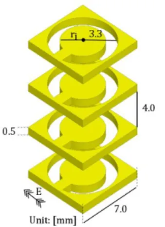
The three-dimensional geometry of the proposed unit-cell is depicted in Fig. 1. This cell is based on a C-shaped slot frequency selective surface, with a periodicity of 7 mm, which is less than half of a wavelength at 18.75 GHz. The metal layer
thickness is 500 µm, and the material is chosen to be conductive, e.g. copper, aluminum, etc. A four-layer stack-up configuration is selected to cover a phase-shift range of 360°. The layer separation is about quarter wavelength (4 mm) at 18.75 GHz.
Fig. 1. Geometry of the proposed MOTA unit-cell based on C-shaped slot frequency selective surface. Dimensions are in mm.
The bandpass response of this unit-cell can be shifted by changing the inner radius ri of the C-shaped slot, as shown in
Fig. 1. In this study, the outer slot radius is fixed and is equal to 3.3 mm.
B. Performance
The metal-only unit-cell (MOUC) has been characterized numerically by full-wave simulations using Ansys HFSS v.15 with periodic boundary conditions. The main results in transmission are presented in Fig. 2 for four frequency points in the down-link band. The unit-cell exhibits a phase-shift of more than 360° (Fig. 2b) when the value of the inner radius ri
varies between 1.5 mm and 2.7 mm. It is interesting to see that the phase curves are almost parallel; this indicates the wide bandwidth properties of the proposed unit-cell. The transmission magnitude at 19 GHz is better than -3 dB and higher degradations are observed at the band edges (18 GHz and 21 GHz) (Fig. 2a).
III. EXAMPLE OF METAL-ONLY TRANSMITARRAY
The proposed MOUCs have been used to design several MOTA prototypes of various sizes. All prototypes radiate at boresight at K-band.
This works is supported by the French National Research Agency (ANR) in the project named TRANSMIL (TRANSmitarray antenna at MILlimeter-wave) under Grant ANR-14-CE28-0023.
Fig. 2. Varition of the transmission coefficients in magnitude (a) and phase (b) of the metal-only unit-cell as a function of the inner diameter ri, for four
frequency points in the down-link band.
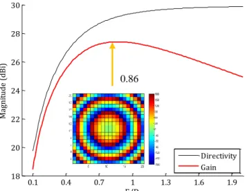
Fig. 3. Computed-directivity and gain of 20-by-20 MOTA for various F/D values at 19 GHz. Inset: phase layout for the optimal F/D value (0.86).
We describe here the main performance of one of these prototypes. It has been designed at 19 GHz and contains 400 MOUCs arranged in a 20-by-20 element square lattice. The
directivity and gain are plotted in Fig. 3 as a function of F/D, assuming no insertion loss and ideal phase compensation at 19 GHz. The TA is illuminated by a 10-dBi feed horn. The optimal F/D maximizing the antenna gain is equal to 0.86, equivalent to a focal length of 122 mm. The computed phase distribution across the transmitarray aperture at 19 GHz is depicted in the inset of Fig. 3 for this optimal position of horn.
The radiation patterns have been computed using array theory [5] and HFSS simulations. The E-plane patterns are represented in Fig. 4. The gain reaches 24 dBi and cross-polarization level below -40 dB in all elevation angles.
Fig. 4. Simulated co-polarized gain components of the MOTA at 19 GHz.
IV. CONCLUSIONS AND PERSPECTIVES
Metal-only unit-cells and transmitarrays have been introduced for very low cost applications, particularly for Satcom ground terminals at down-link band. The corresponding unit-cells are based on pass-band C-shaped frequency selective surfaces. Fabrication of the prototypes is under progress and detailed experimental results will be presented during the conference (fabrication techniques, assembly, and performance in radiation). The proposed concept can be scaled for other applications (e.g., up-link Satcom in Ka-band, outdoor flat antenna panels for 5G access points and backhaul links in Ka-band and V-band).
REFERENCES
[1] A. H. Abdelrahman, A. Z. Elsherbeni, and F. Yang, “Transmitarray antenna design using cross slot elements with no dielectric substrate,”
IEEE Antennas Wireless Propag. Lett., vol. 13, pp. 177–180, 2014.
[2] B. Rahmati and H. R. Hassani, “High-efficient wideband slot transmitarray antenna,” IEEE Trans. Antennas Propag., vol. 63, no. 11, pp. 5149–5155, Nov. 2015.
[3] G. Liu, H. Wang, J. Jiang, F. Xue, and M. Yi, “A high efficiency transmitarray antenna using double split rings slot elements,” IEEE
Antennas Wireless Propag. Lett., vol. 14, pp. 1415-1418, 2015.
[4] R. Y. Wu, Y. B. Li, W. Wu, C. B. Shi, and T. J. Cui, “High-gain dual-band transmitarray,” IEEE Trans. Antennas Propag., vol. 65, no. 17, pp. 3481–3488, Jul. 2017.
[5] K. T. Pham, R. Sauleau, E. Fourn, F. Diaby, A. Clemente and L. Dussopt, "Dual-band transmitarrays with dual-linear polarization at Ka-band," IEEE Trans. Antennas Propag., vol. 65, no. 12, pp. 7009-7018, Dec. 2017. 1.5 1.7 1.9 2.1 2.3 2.5 2.7 -15 -12 -9 -6 -3 0
Inner radius of C-shaped slot, ri (mm) (a) T ra ns m is si on m ag ni tu de ( dB ) 18 GHz 19 GHz 20 GHz 21 GHz 1.5 1.7 1.9 2.1 2.3 2.5 2.7 -180 -135 -90 -45 0 45 90 135 180
Inner radius of C-shaped slot, ri (mm) (b) T ra ns m is si on p ha se ( °) -90 -75 -60 -45 -30 -15 0 15 30 45 60 75 90 -15 -10 -5 0 5 10 15 20 25 theta(°) G ai n( dB i) E-plane Cardinal Plane H-plane 0.1 0.4 0.7 1 1.3 1.6 1.9 18 20 22 24 26 28 30 F/D Ma gn itu de ( dB i) Directivity Gain 0.86