Publisher’s version / Version de l'éditeur:
Questions? Contact the NRC Publications Archive team at
[email protected]. If you wish to email the authors directly, please see the
https://publications-cnrc.canada.ca/fra/droits
L’accès à ce site Web et l’utilisation de son contenu sont assujettis aux conditions présentées dans le site LISEZ CES CONDITIONS ATTENTIVEMENT AVANT D’UTILISER CE SITE WEB.
ConMat'05 Third International Conference on Construction Material: Performance,
Innovations and Structural Implications[Proceedings], pp. 1-10, 2005-08-01
READ THESE TERMS AND CONDITIONS CAREFULLY BEFORE USING THIS WEBSITE.
https://nrc-publications.canada.ca/eng/copyright
NRC Publications Archive Record / Notice des Archives des publications du CNRC :
https://nrc-publications.canada.ca/eng/view/object/?id=38c76c4f-dc93-441a-9dfe-9b346248acf1 https://publications-cnrc.canada.ca/fra/voir/objet/?id=38c76c4f-dc93-441a-9dfe-9b346248acf1
NRC Publications Archive
Archives des publications du CNRC
This publication could be one of several versions: author’s original, accepted manuscript or the publisher’s version. / La version de cette publication peut être l’une des suivantes : la version prépublication de l’auteur, la version acceptée du manuscrit ou la version de l’éditeur.
Access and use of this website and the material on it are subject to the Terms and Conditions set forth at
Seismic retrofitting of rectangular bridge piers with CFRP
Seismic retrofitting of rectangular bridge piers with
CFRP
Chagnon, N.; Massicotte, B.
NRCC-48365
A version of this document is published in / Une version de ce document se trouve dans :
ConMat’05 Third International Conference on Construction Material:
Performance, Innovations and Structural Implications, Vancouver, B.C.,
August 22-24, 2005, pp. 1-10
Seismic retrofitting of rectangular bridge piers with CFRP
N. Chagnon and B. Massicotte
École Polytechnique de Montréal, Canada
Abstract
It has been observed during past seismic events that rebar splices at the bottom of bridge columns can produce collapse if not properly confined. Retrofitting techniques have been developed over the last thirty years to face this problem. These techniques, however, are difficultly applicable to rectangular columns with aspect ratio exceeding 2:1 because their efficiency relies on confinement. In order to address that issue, a research project has been initiated developing new concepts for retrofitting rectangular columns with inadequate lap splice detailing. One proposed technique is based on the use of carbon fibre reinforced polymer (CFRP) to limit the opening of splitting cracks that are responsible for the bond failure. The paper presents the main results of the flexural tests. The retrofitted specimens showed significant improvements compared to the control specimen: the use of CFRP changed the failure mechanism and delayed the opening of splitting cracks sufficiently for the reinforcement to yield. The brittle failure of the control specimen changed to a very ductile one for the retrofitted specimens.
Keywords: Bridge piers, seismic strengthening, lap splice, ductility
Professor Bruno Massicotte
Department of Civil, Geological and Mining Engineering École Polytechnique de Montréal
P.O. Box 6079, Station Centre-ville, Montréal QC, Canada, H3C 3A7
Email:[email protected]
1. Introduction
In the last decades, considerable progress has been made on understanding the effects of earthquakes on bridges and on means to ensure adequate structural behaviour. Based on past experience several reinforcement detailing are known to yield non ductile failure in the case of major seismic events.
Lap splice at the base of bridge piers was a common practice until recently. With inadequate confinement, this detail can lead to a brittle failure. In order to improve the behaviour of bridge piers that contain such detail, strengthening techniques with steel, concrete or FRP jackets have been developed during the past 30 years [1,2]. Theses techniques rely upon the enhancement of the confinement and have shown satisfactory performance for circular, square or lightly rectangular columns. However, they are less efficient and hard to implement to rectangular columns with an aspect ratio exceeding 2:1.
A research project was recently initiated at École Polytechnique de Montréal for addressing the problem of strengthening rectangular bridge pier in the lap splice region. One of the retained concepts consists of applying CFRP to limit the opening of splitting cracks responsible for the bond failure. This technique was studied using pull-out tests, flexure tests and finite element analysis [3]. This paper presents the main results of the flexure tests.
2. Reinforcement lap splice failure mechanism
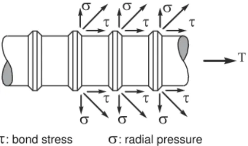
In the lap splice region, forces are transmitted between lapped bars through the surrounding concrete. As indicates Figure 1, the bar tensile force is transferred to the concrete through an inclined force. The force tangential component is associated with the adherence stress whereas the radial component creates a tension ring in the concrete around the bar [4], illustrated in Figure 2. This ring initiates the formation of splitting cracks that propagate in the concrete, leading to bar slip and eventually the failure of the anchorage.
σ
T
σ τ
τ: bond stress σ: radial pressure σ
σ σ σ
τ τ
τ τ τ
Figure 1. Forces on concrete induced by the anchorage of deformed bars.
In new constructions, anchorage failures are usually controlled by providing a confinement to the concrete using closely spaced stirrups or spirals. However, in the case of existing structures, reinforcement details are often inadequate which requires strengthening structural components if a ductile behaviour is needed.
α α
Figure 2. Tension ring around reinforcement [4].
3. Proposed strengthening technique for rectangular columns
Using CFRP for strengthening bridge piers in the lap splice region is an attractive solution for several reasons when compare to other alternatives. In addition to the usual advantages of carbon fibres as an efficient strengthening technique, using CFRP does not increase column rigidity, an important aspect in capacity design whereas the stiffness of the strengthening material provides an advantage for controlling splitting crack opening.
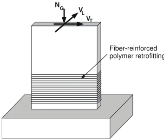
The technique used in this project differs from the traditional confining jacket approach because it does not count on the enhanced confinement to increase column ductility. In conventional technique, confinement forces apply at section corners whereas the proposed technique counts on a local confining effect. The objective of the proposed technique is to limit the opening of the splitting cracks that form along the bars in the lap splice region by orienting FRP in the transverse direction, as illustrated in Figure 3. It is assumed that the rigidity of the FRP would allow to maintain a pressure on the bars, postponing the bar slip until yielding, enabling the development of a plastic hinge in the lap splice region. Applying FRP in the transverse direction also contributes to strengthen column in shear in the transverse direction. It is likely that the proposed technique applied to rectangular columns should be less efficient than conventional FRP wrapping around square columns. It is however believed that in moderate seismic zone, the propose technique would be sufficient to strengthen deficient columns at an acceptable level.
VL VT
NG
Fiber-reinforced polymer retrofitting
4. Experimental program
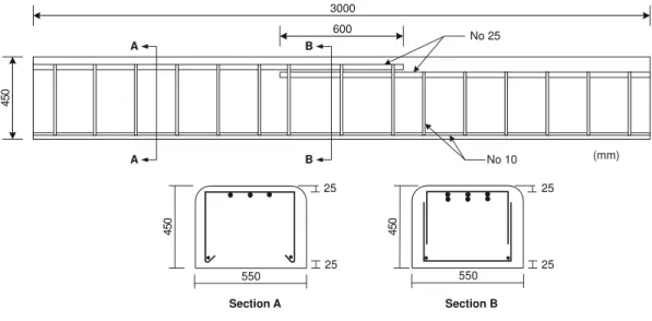
The preliminary research project comprised three 450 × 550 × 3 000 mm specimens (Figure 4) aimed at representing a slice of a rectangular column. The objective of these tests is to evaluate the potential of the proposed technique. The nominal width of the specimens was 450 mm. However, to provide an adequate anchorage to FRP without inducing any confinement stress at the corners, the specimens were made 100 mm wider (50 mm on each side). The reinforcement details were similar to those of bridge piers designed before the 1988 bridge code [5] : each specimen was reinforced with 3 No 25 bars spliced over 600 mm in the central portion, which corresponds to 24 bar diameters. Transverse reinforcement consisted in No 10 stirrups spaced at 300 mm in the central lap splice region and 200 mm outside that region. One specimen was used as reference (R) whereas the remaining two were strengthened with two (C2) and four (C4) layers of CFRP in the lap splice region only.
The average hardened concrete properties measured at the time of testing were : ƒc' = 36 MPa, Ec = 30 280 MPa and ν = 0.22. A 400W grade was specified for the reinforcement. The average
properties measured on two No 25 bars were ƒy = 488 MPa, ƒu = 670 MPa and Es = 208 000 MPa.
600 3000 4 5 0 No 25 No 10 (mm) A A B B 25 550 45 0 25 550 45 0 25 25 Section A Section B
Figure 4. Specimen dimensions.
Carbon fibre fabric was used to strengthen specimens C2 and C4 and was applied according to supplier instructions. According to the supplier technical information, this material has a nominal tensile strength of 717 MPa and an effective elastic modulus of 65 000 MPa. The fabric was applied on a length equal to 640 mm. The specimens were stored at room temperature at least 7 days before testing.
5. Instrumentation and test setup
Stress variations of the spliced central bars of each specimen were measured with pairs of strain gauges at 300 mm and 600 mm from the bars free end. Two strain gauges were installed on the compression side in the longitudinal direction, on the surface of concrete for the reference specimen and on the composite material for specimens C2 and C4.
On the tensile face of the reference specimen, strains in the longitudinal direction were measured by the mean of nine pairs of mechanical strain targets with a gauge length of 250 mm, three pairs above each longitudinal bar. Splitting crack opening above each bar was measured at sections 1, 2 and 3 (Figure 5) with nine pairs of mechanical targets with a gauge length of 150 mm.
For specimens C2 and C4 strain gauges were installed on the tensile face of the composite material as indicated in Figure 5. On specimens C2 and C4 two strain gauges (1D and 3D) were installed above the central lapped bars at sections 1 and 3. Also, to study the transverse distribution of stresses in the composite, additional strain gauges were installed on specimen C2 (2A to 2G).
2D 2C 2B 2A Sections 1 and 3 Beam C2 and C4 Section 2 Beam C4 Section 2 Beam C2 1D, 3D 2D 2 1 3 2E 2F 2G
Figure 5. Electrical strain gauges locations in specimens C2 and C4.
The test setup is shown in Figure 6. The load was applied slowly and monotonically with 10 kN increments up to concrete cracking and with 20 kN increments afterward, allowing for manual readings for the reference specimen and for visual observations. Electronic readings were sampled regularly.
Bending moments were computed from static and verified using the measured strains and the net bar area at the instrumented sections. The theoretical ultimate bending moment calculated using the measured properties applying the conventional R/C beam theory is 250 kN-m.
800 mm 1000 mm 800 mm
200 mm 200 mm
600 mm
6. Results and discussion 6.1 Reference beam
Flexural cracks appeared at a bending moment of 42.7 kN-m and were spaced at approximately 200 mm outside the lap splice region and nearly 300 mm in the splice region, corresponding to the stirrup spacing, as illustrated in Figure 7. Splitting cracks were visible at a bending moment of 90 kN-m. They formed mainly in the lap splice region above longitudinal bars as shown in Figure 8. The reference specimen failure occurred at a bending moment of 230 kN-m. It was brittle and sudden, with the spalling of the concrete cover at section 3 (Figure 5) and before the onset on reinforcement yielding.
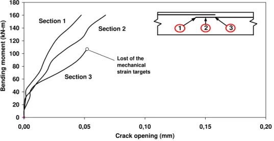
Figure 9 presents the average crack opening measured with the mechanical strain gauges in the lap splice region (sections 1, 2 and 3). As indicated in Figure 9, the first signs of cracking (corresponding to a crack width of approximately 0.005 mm) occurred at bending moments of approximately 20 kN-m, 40 kN-m and 50 kN-m at sections 3, 2 and 1 respectively. It can be observed that, for a given load, crack widths increase from section 1 to 3. Crack opening at Section 3 could not be measured throughout the test due to excessive concrete spalling.
70 1000 1000 1000 450 100 110 80 36 40 47 50 30 36 47 50 100 29 30 36 40 128 29 30 30 47 70 76 100 30 47 80 36 40 70 80 110 110
Figure 7. Cracking of the vertical face of reference specimen.
1000 1000 1000 550 100 100 110 100 110100 100 100 90 90 90 90 90 110 60 56110 100 80 100 110 80 110 110
Figure 8. Cracking on the tensile face of reference.
6.2 Strengthened specimens C2 and C4
Specimens C2 and C4 experienced a ductile failure with large rotations and the formation of a plastic hinge. Large strains were measured in the reinforcement at Section 3. The specimens eventually failed due to concrete crushing outside the strengthened region. This indicates that the failure zone moved away from the lap splice region to the unconfined section which eventually controls the ultimate behaviour. The maximum bending moments applied to specimens C2 and C4 were equal to 273 kN-m and 275 kN-m respectively, above the theoretical maximum value of 250 kN-m, as an indication of possible strain hardening of the reinforcement.
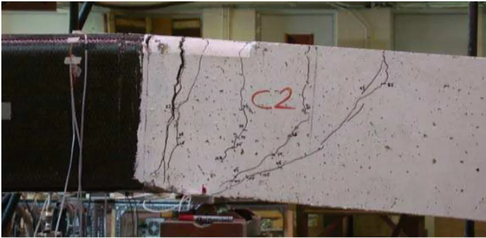
As illustrated in Figures 10 and 11, failure occurred outside the lap splice region. The main cracks developed approximately 100 mm from the end of the CFRP wrapping. In specimen C2, concrete delamination was noticeable underneath the CFRP at failure. This phenomenon was not clearly identified for specimen C4.
0 20 40 60 80 100 120 140 160 180 0,00 0,05 0,10 0,15 0,20 Crack opening (mm) B e nding mome nt ( k N -m) Section 2 Section 3 Section 1 Lost of the mechanical strain targets 1 1 2 2 3 3
Figure 9. Splitting crack opening on the tensile face of the reference specimen.
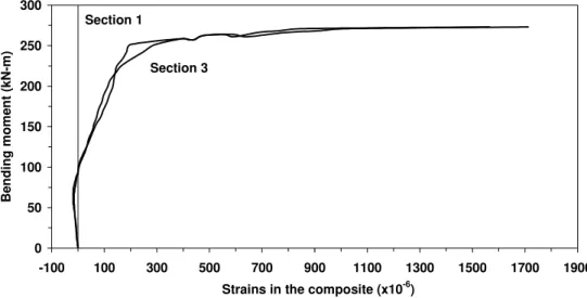
Strains measured on the composite material above the central bars at sections 1 and 3 of specimens C2 and C4 are shown in Figures 12 and 13 respectively. At low loading level, negative strains were measured due to the Poisson's effect on the concrete in tension. Shortly after cracking, the composite material was subjected to tensile forces until specimen failure. Due to the presence of the composite material it is difficult to establish if cracking was delayed. However, the progression of the crack opening was certainly restrained.
For specimen C2 (Figure 12), the rapid strain increase in the composite indicates that important lateral pressure was applied to the concrete. An interesting point is that both Sections 1 and 3 experienced a very similar behaviour. This observation indicates that, contrarily to the reference specimen where splitting cracks were larger on one end (Figure 9), FRPs limit crack opening at the critical section, enabling a more uniform distribution of the anchorage stresses over the lap splice region.
Strain magnitude in specimen C4 (Figure 13) were significantly less than those of specimen C2, indicating that adding two layers of composite contributed to reduce substantially transverse strains. From this interesting observation it can be concluded that 4 layers of carbon fibres could have sustained higher radial pressure that could have been induced with higher reinforcement ratio or larger bar size.
Strain measurements at Section 2 of specimen C2 indicate that the strain in the composite material decreased rapidly while getting away from the bars. No stresses developed in the composite near the corners indicating that no confinement were present. This shows that the anticipated crack opening restraint mechanism offered by the FRP actually developed and enabled to significantly
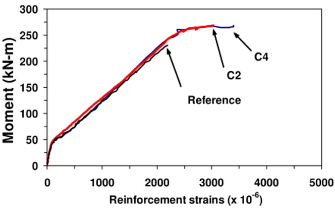
improve the bond anchorage of the bars in the lap splice region. This has significantly improved the ductility of the section. Most of the ductility developed outside the strengthened region where large cracks developed. Although no instruments could adequately compare the three specimens, strain gauge measurement in the strengthened regions presented in figure 14 illustrates partially the significant improvement. It could be also concluded that the testing technique represented relatively well the behaviour of a slice of a rectangular section.
Figure 10. Side view of specimen C2 after failure.
0 50 100 150 200 250 300 -100 100 300 500 700 900 1100 1300 1500 1700 1900
Strains in the composite (x10-6)
B e ndin g mom e nt ( k N -m) Section 1 Section 3
Figure 12. Transverse strains on specimen C2 above the central bars.
0 50 100 150 200 250 300 -100 100 300 500 700 900 1100 1300 1500 1700 1900
Strains in the composites (x10-6)
B e ndin g mom e nt ( k N -m) Section 1 Section 3
Figure 13. Transverse strains on specimen C4 above the central bars.
7. Conclusions
The main conclusions drawn from this exploratory project are:
• The reference specimen exhibited a brittle failure before yielding of the flexural reinforcement due to concrete spalling induced by the splitting of the concrete.
• A plastic hinge formed outside the strengthened region in specimens C2 and C4 as the failure was governed by the concrete strength in compression long after yielding of the flexural reinforcement.
• Increasing the number of composite layers reduces the transverse strains, which indicates that the composite thickness can be designed according to the required level.
• Composite material limits crack opening at critical sections which enables to distribute more uniformly the anchorage stress over the lap splice region and allows longer portions of the reinforcing bars to efficiently participate in the bar anchorage.
• The anticipated crack opening restraint mechanism offered by the FRP took place and enabled to significantly improve the bond anchorage of the bars in the lap splice region. • Using FRPs does not affect the column rigidity which is an advantage while applying the
capacity design approach.
0 50 100 150 200 250 300 0 1000 2000 3000 4000 5000 Reinforcement strains (x 10-6) M o men t ( k N -m) Reference C2 C4
Figure 14. Strain measurements in the flexural reinforcement.
Finally, it can be concluded from this exploratory project that the proposed technique could be efficiently used to strengthen rectangular columns. Further research is however required to better understand the involved mechanisms and extent the range of experimental parameters for eventually propose a design method. Test on actual rectangular sections should be carried out in order to verify the experimental technique adopted in this project.
8. Acknowledgements
The authors acknowledge the financial support of NSERC and ISIS Canada, Sika and Lafarge. The technical personnel of École Polytechnique de Montréal Structures Laboratory are greatly appreciated.
9. References
1. Priestley, M.J.N., Seible, F. and Calvi, M. 1996, "Seismic design and retrofit of bridges", John Wiley & Sons, Inc., New-York, 686p.
2. Seible, F., Priestly, M.J.N. and Innamorato, D. 1997, "Seismic retrofit of RC columns with continuous carbon fiber jackets", Journal of composites for construction, 1(2): 52-62.
3. Chagnon, N. 2004, "Seismic strengthening of reinforced concrete bridge piers with composite material" (in French), Master Degree Thesis, Ecole Polytechnique de Montréal, Montreal, Canada. 4. Cairns, J. and Abdullah, R.B. 1996, "Bond strength of black and epoxy-coated reinforcement – A theoretical approach. ACI Structural Journal, 93(4): 362-369.