Publisher’s version / Version de l'éditeur:
Proceedings of the 6th International Conference on the Application of Physical
Modelling in Coastal and Port Engineering and Science (Coastlab16), 2016-05
READ THESE TERMS AND CONDITIONS CAREFULLY BEFORE USING THIS WEBSITE. https://nrc-publications.canada.ca/eng/copyright
Vous avez des questions? Nous pouvons vous aider. Pour communiquer directement avec un auteur, consultez la première page de la revue dans laquelle son article a été publié afin de trouver ses coordonnées. Si vous n’arrivez pas à les repérer, communiquez avec nous à PublicationsArchive-ArchivesPublications@nrc-cnrc.gc.ca.
Questions? Contact the NRC Publications Archive team at
PublicationsArchive-ArchivesPublications@nrc-cnrc.gc.ca. If you wish to email the authors directly, please see the first page of the publication for their contact information.
NRC Publications Archive
Archives des publications du CNRC
This publication could be one of several versions: author’s original, accepted manuscript or the publisher’s version. / La version de cette publication peut être l’une des suivantes : la version prépublication de l’auteur, la version acceptée du manuscrit ou la version de l’éditeur.
Access and use of this website and the material on it are subject to the Terms and Conditions set forth at
Physical modelling to support the rehabilitation and design
optimization of the jetties at the mouth of the Columbia River
Knox, Paul; Baker, Scott; Millar, Gillian; Yoyner, Brian; Moritz, Hans; Charles,
Lynda
https://publications-cnrc.canada.ca/fra/droits
L’accès à ce site Web et l’utilisation de son contenu sont assujettis aux conditions présentées dans le site LISEZ CES CONDITIONS ATTENTIVEMENT AVANT D’UTILISER CE SITE WEB.
NRC Publications Record / Notice d'Archives des publications de CNRC:
https://nrc-publications.canada.ca/eng/view/object/?id=b728a2d3-c8cb-4503-acbd-ef9a2099df70 https://publications-cnrc.canada.ca/fra/voir/objet/?id=b728a2d3-c8cb-4503-acbd-ef9a2099df70Proceedings of the 6
thInternational Conference on the Application
of Physical Modelling in Coastal and Port Engineering and Science
(Coastlab16)
Ottawa, Canada, May 10-13, 2016
Copyright ©: Creative Commons CC BY-NC-ND 4.0
PHYSICAL MODELLING TO SUPPORT THE REHABILITATION AND DESIGN
OPTIMIZATION OF THE JETTIES AT THE MOUTH OF THE COLUMBIA RIVER
PAUL KNOX1, SCOTT BAKER1, GILLIAN MILLAR2, BRIAN JOYNER2, HANS MORITZ3, LYNDA CHARLES31 National Research Council of Canada, Canada, paul.knox@nrc.ca
2 Moffatt & Nichol, USA, 3 US Army Corps of Engineers, USA
ABSTRACT
Originally constructed between 1885-1939, the three jetties protecting the Mouth of the Columbia River (MCR), the North Jetty, the South Jetty, and Jetty A have been progressively damaged due to storm wave attack and the loss of the sand shoal material that comprise their foundation. The MCR jetties are an essential part of maintaining the Columbia/Snake River navigation system, a significant export gateway for the west coast. In late 2014 Moffatt & Nichol (M&N) and the National Research Council of Canada (NRC) were commissioned by the US Army Corps of Engineers (USACE) to conduct physical model studies to inform and guide the design of repair works for two of the jetties, the North Jetty and Jetty A. Due to the exposed Pacific North-west conditions, strict environmental constraints, and the historic evolution of the existing structures, most notably a substantial relic stone foundation, the proposed repair works were complex and unconventional. Two separate three-dimensional physical models were constructed and used to investigate the performance of the proposed repairs for the two unique physical and functional settings at each jetty. Alternatives included rock armour and concrete armour units, tested under a range of site-specific design conditions, including extreme water levels and harsh wave conditions. This paper summarizes the physical modelling studies, the unique challenges presented by the complex bathymetry, and the important role physical modelling had in verifying and optimizing the reconstruction proposed for the North Jetty and Jetty A. The physical modelling provided essential identification of the near-structure three-dimensional interactions and guided the quantification of damages leading to optimization of the final designs.
KEYWORDS: Physical modelling, jetties, breakwaters, Columbia River
1 INTRODUCTION
Figure 1 depicts the Mouth of the Columbia River’s jetty system. Originally constructed between 1885 and 1939, the system consists of three rubble-mound jetties constructed on massive tidal shoals and designed to minimize navigation channel maintenance and provide safe transit between the Pacific Ocean and the Columbia River. The North and South jetties have been repaired several times since their original construction; the latest repairs occurred in 2015 on the North Jetty and 2006-2007 on the South Jetty. Jetty A has only been repaired once since initial construction, in 1965. The recent repairs on the jetties were interim repairs, designed to maintain jetty functionality until a longer-term maintenance and repair plan was designed. Critical portions of the jetties could breach during a large storm event, allowing sand to be transported and deposited directly into the navigation channel. Such an event could shut down commercial navigation at the entrance to the river system, requiring expensive emergency repairs to the jetty and dredging to restore channel depth. The USACE completed an analysis that evaluated the causes and problems associated with the current structural instability of the MCR jetty system. This analysis resulted in a recommendation to improve structural reliability, to extend functional life, and most significantly, to maintain deep-draft navigation. A risk-based, life-cycle analysis was used to examine jetty performance (past and future) and develop jetty modification alternatives through a phased strategy for jetty repair. The repair of the Jetty A and North Jetty roundheads were deemed critical steps to ensuring the functionality of the MCR jetty system. The proposed jetty rehabilitation designs were to be tested by physical modelling to verify and optimize the design based on the structural stability of the armour. The jetty rehabilitation designs feature rubble-mound breakwater designs, armoured with either rock or concrete armour units.
Figure 1. Mouth of the Columbia River jetty system. (Source: Google Earth)
2 PHYSICAL MODELLING SETUP AND METHODOLOGY 2.1 North Jetty
A 1:47.9 scale three-dimensional physical model of the MCR North Jetty complete with the surrounding bathymetry, navigation channel, and a portion of the damaged existing jetty (referred to as the relic structure) were constructed in a 36m by 30m wave basin at the NRC in Ottawa. The model bathymetry was formed in concrete based on high-resolution soundings from the project site. The model was designed such that the orientation of the wave generator was along the 150°-330° plane (waves generated perpendicularly from the wave machine would be at 240°N). Results from M&N’s numerical modeling effort showed the near shore wave directions of interest ranged from 230°N to 260°N at the location of the wave machine. Because of the large variation in depth between the shallow north side of the jetty and deeper south side (the entrance channel), the natural contours of the bathymetry were faithfully replicated above the -25ft (NAVD) contour on the north, and faithful above -70ft contour to the south. The relic structure below -25ft was replicated by inserting rocks in the model concrete to roughen the surface. Above -25ft the relic structure was constructed out of rock materials and built to cross-section designs provided by M&N. The layout of the model in the testing basin is shown in Figure 2.
The wave climate in the vicinity of the project was studied in detail by M&N in order to determine the design wave conditions for the North Jetty refurbishment, and also to develop a set of sea states to be used as testing conditions in the physical model. Due to the relatively deep channel to the south of the jetty (-70ft), the shallow waters to the north of the jetty (-10ft to -20ft), and the presence of the existing damaged and submerged relic structure offshore of the intended location of the new jetty roundhead, the bathymetry near the project site and inside the physical model domain was highly complex. M&N utilized several different numerical models to simulate the transformations of offshore deep-water waves closer to the shore to be used as the input wave conditions for the physical model. Based on the results of these models, as well as a desire to keep the testing program to a reasonable length, eleven different short-crested wave conditions were selected by M&N and the USACE to test the performance of the model breakwater. The selected sea-states are shown in Table 1.
Figure 2. North Jetty model layout in the NRC 3D wave basin at a scale of 1:47.9.
Table 1. Sea-states selected for the testing phase of the North Jetty model
Case WL (ft, NAVD) Hs (ft) Tp (s) Direction (°N)
Shakedown 16.8 4.9 14 245 D 5.25 19.7 17 260 R 10.8 21.3 14 260 S 10.8 21.3 20 260 P 10.8 26.2 14 230 Q 10.8 26.2 20 230 I 14.8 26.2 20 230 M 14.8 21.3 14 260 K 14.8 21.3 17 260 L 14.8 21.3 20 260 N 16.8 26.2 17 230 O 16.8 21.3 17 260
Prior to the construction of the model jetty, a series of undisturbed wave tests (wave calibrations) were conducted to both prepare and verify the wave machine control signals required to generate these sea-states in the physical model, and also to investigate the transformations of the waves as they propagate through the project site. For the calibrations, the locations of the physical model wave probes were used as extraction points in the M&N Boussinesq model, and the wave generation signals for the sea-states were tuned (amplified) to try and match these targets as much as possible. Target wave probes were selected near the offshore boundary of the model – on the faithfully replicated bathymetry of the model, but slightly inland so that any wave transformations and/or breaking caused by the unfaithful bathymetry had already occurred.
20 S h o rt-c re s ted w a v e s fro m 21 0 ° to 2 7 0 °
S
c
a
le
1
:4
7
.9
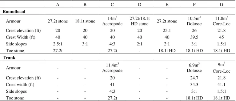
1617 4 S h o rt-c re s ted w a v e s fro m 21 0 ° to 2 7 0 °The rehabilitation plans for the North Jetty do not include repairs to the existing outer relic structure that is mostly submerged. However, it was deemed critical to properly model the submerged structure due to its effects on the waves reaching the emergent jetty and new roundhead repair. The outer relic armour (below -25ft) was cast directly into the bathymetry surface, and rocks were embedded in the surface during the concrete to simulate the roughness of the relic structure. The same surface roughening treatment was used along the steep slopes to the south of the jetty. The upper portion of the outer relic jetty (above -25ft) was modelled as a rubble-mound structure, built to cross-section surveys provided by M&N, and armoured with oversized material in order to minimize damage and degradation of the outer structure, and to minimize required construction efforts during subsequent rebuilds of the new jetty structure. The oversized outer relic armour was offshore of the toe of the new roundhead, as the relic armour stone immediately adjacent the new roundhead was modelled with a different material and sized to more faithfully represent the submerged stability of the prototype relic stone. Once constructed, the outer relic structure maintained the same configuration for the entire testing program, was painted purple, and required little to no repairs during rebuilds between test series. The rehabilitation designs for the North Jetty focus on installing a new roundhead with 200ft of trunk on top of the existing relic structure and mating the new structure to the existing jetty trunk. The design of the existing jetty trunk is a rubble-mound structure made from 18.1t armour stone with a crest width and elevation of 30ft and 25.1ft, respectively. Approximately 150ft of the existing jetty trunk was constructed in the model. Seven different designs for the new North Jetty roundhead rehabilitation were tested in the physical model. The main features for each design (or test series, A-G) are summarized in Table 2; note that some of the structures utilized a high density (HD) stone in their construction. Figure 3 shows an example of one of the models in the wave basin after construction.
Table 2. General characteristics of the North Jetty models.
A B C D E F G
Roundhead
Armour 27.2t stone 18.1t stone 14m
3 Accropode 27.2t/18.1t HD stone 27.2t stone 10.5m3 Dolosse 11.8m3 Core-Loc Crest elevation (ft) 20 20 20 20 25.1 26 21.8 Crest Width (ft) 40 40 40 40 40 39.5 45 Side slopes 2.5:1 3:1 4:3 2:1 2:1 3:1 1.5:1 Toe stone 27.2t 27.2t - 18.1t HD 18.1t HD 18.1t HD Trunk Armour - - 11.4m 3 Accropode - - 6.9m3 Dolosse 9m3 Core-Loc Crest elevation (ft) - - 20 - - 24.7 21.8 Crest width (ft) - - 41 - - 34.3 41.1 Side slopes - - 4:3 - - 3:1 1.5:1 Toe stone - - 27.2t - - 18.1t HD 18.1t HD
The model jetties were rubble-mound structures based on designs provided by M&N. Careful attention was given to the location, dimensions, composition, and methods of construction to ensure that they replicated the existing and proposed designs accurately and faithfully. The core and under-layers were constructed with care using rock materials selected to replicate the submerged stability and/or permeability of the prototype materials. Several different kinds of armour stone and concrete armour units were tested in the physical model as potential candidates for the prototype design. Accropodes, Core-Locs, and Dolosse units were sized and selected for the design by M&N and USACE engineers, and placed in the model to match their specifications.
Figure 3. Photograph of the North Jetty model in the NRC multidirectional wave basin.
2.2 Jetty A
A 1:36.1 scale three-dimensional physical model of the outer portion of Jetty A and the surrounding seabed (including the submerged relic structure) was constructed in a 62.5m by 14.2m wave basin at the NRC in Ottawa. Due to its location within the MCR, the range of wave directions approaching Jetty A are quite limited due to the partial sheltering afforded by the North and South jetties. Based on a thorough numerical modelling analysis by M&N, the mean wave approach angle at the end of the jetty was expected to be from 226°, and therefore the basin was oriented to generate long-crested waves from this direction. Again, the model bathymetry was formed in concrete based on high-resolution soundings from the project site. Near to the relic structure, the deeper bathymetry contours (below -75ft) were modified slightly to be more perpendicular to the incident waves to prevent sidewall reflections. In the direct vicinity of the existing jetty, all contours above -75ft were modelled faithfully. The outer 820ft section of Jetty A is heavily damaged and lies mostly underwater. However, its inclusion in the physical model was of critical importance due to the unique wave transformations and wave focusing it would cause. The lower portion of the outer relic structure (-20ft and below) was built into the concrete bathymetry as a rigid structure, as it is presumed to be relatively statically stable. The upper portion of the outer relic structure (-20ft and above) was modelled as a rubble-mound structure using slightly oversized stone to minimize the need for repairs between structure rebuilds. The close-up view of the model layout in the testing basin is shown in Figure 4.
Outer Relic
-70ft to -60ft
-25ft to -20ft
New Roundhead
Relic
Existing
Trunk
Bathymetry contour Additional wave absorbers for reflected waves
-30.48m (-100ft) -22.86m (-75ft) -7.620m (-25ft) -30.48m (-100ft) -22.86m (-75ft) -15.24m(-50ft) -7.620m (-25ft)
Additional wave absorbers for reflected waves
WP01 WP02 WP03 WP07 WP09 WP11 WP04 WP05 WP08 WP06 WP10 Cam 1 Cam 2 Cam 3 WP13 Wave gauge
Outer relic structure
Dummy roundhead Jetty A Trunk
Jetty A Roundhead Long-crested waves from 226°
Figure 4. Jetty A model layout in the NRC 2D wave basin at a scale of 1:36.1.
The rehabilitation designs for Jetty A focus on installing a new roundhead and 240ft of trunk on top of the existing relic structure and mating the new structure to the existing jetty trunk. The design of the existing jetty trunk is a rubble-mound structure made from 9.1t armour stone with a crest width and elevation of 30ft and 23.4ft, respectively. Approximately 300ft of the existing jetty trunk was constructed in the model. Four different designs for the new Jetty A roundhead rehabilitation were tested in the physical model. The main features for each design (or test series, A-D) are summarized in Table 3. Figure 5 shows an example of one of the models in the wave basin after construction.
Table 3. General characteristics of the Jetty A models.
A B C D
Roundhead
Armour 18.1t stone 23.0t stone 6.2m
3 Core-Loc 23.0t stone Crest elevation (ft) 19.4 23.4 19.4 19.4 Crest Width (ft) 40 40 36 40 Side slopes 2:1 2:1 3:2 2:1 Toe stone 18.1t 23.0t 16.2t 23.0t Trunk
Armour 10.9t stone 10.9t stone 5.0m
3
Core-Loc 10.9t stone Crest elevation (ft) 19.4 23.4 19.4 19.4
M&N utilized several different numerical models to simulate the transformations of offshore deep-water waves closer to the shore to be used as the input wave conditions for the physical model. Based on the results of these models, as well as a desire to keep the testing program to a reasonable length, twelve different long-crested wave conditions were selected by M&N and the USACE to test the performance of the model breakwater. The selected seastates are shown in Table 4. Prior to the construction of the model jetty, a series of undisturbed wave tests (wave calibrations) were conducted to both prepare and verify the wave machine control signals required to generate these sea-states in the physical model, and also to investigate the transformations of the waves as they propagate through the project site.
Table 4. Seastates selected for the testing phase of the model
Case WL (ft, NAVD) Hs (ft) Tp (s) Direction (°N)
A 5.9 10.9 17 226 B 5.9 12.2 17 226 D 10.3 13.5 20 226 E 10.3 14.8 20 226 F 10.3 14.8 17 226 G 12.2 14.8 20 226 H 12.2 16.6 17 226 I 12.2 14.0 17 226 J 5.9 11.6 20 226 K 7.9 12.7 17 226 L 10.3 14.2 20 226 M 10.3 14.2 16 226
Figure 5. Photograph of the Jetty A model in the NRC wave basin.
3 INSTRUMENTATION AND DATA ANALYSIS
Vertical fluctuations of the free surface (waves) were measured in both models using capacitance-wire wave gauges, including a four-probe directional wave array. NRC’s GEDAP software was used for all analysis procedures. GEDAP is a general-purpose software system for the synthesis, analysis and management of laboratory data that also includes modules for real-time experiment control and data acquisition functions. Standard GEDAP time-domain, frequency-domain, and statistical analysis algorithms were applied to analyze the measured wave conditions in considerable detail. A photographic damage analysis system comprising five remotely-operated digital cameras in fixed locations was used in both studies to monitor the movement of armour stone/units on the surface on the jetty. The movement of individual stones/units were detected by comparing photographs taken before and after a test segment.
Outer Relic
New Trunk &
Roundhead
4 RESULTS AND DISCUSSION 4.1 North Jetty
The waves selected for the physical model represented energetic storm conditions across a range of water levels from two directions, 230°N and 260°N. The unique bathymetry near the site and the presence of the relic structure created a very complex near-shore wave climate. The bathymetry to the north of the relic jetty and new jetty roundhead was relatively shallow (-20ft at the roundhead toe) while the depths in the entrance channel to the south were very deep (-60 to -80ft). This led to very different wave characteristics on the opposing sides of the jetty – the waves on the north were depth limited and featured a lot of broken waves. The submerged relic jetty heavily influenced the incoming wave energy via breaking, refraction, and diffraction. Waves approaching the site from 230°N propagated in relatively deep water on the south side of the jetty, refracting only slightly and generally plunging onto the south side of the new jetty roundhead. On the north side of the jetty/relic structure the waves refracted around in the shallower water and spilling breakers ran along the north side of the jetty. The combination of these two effects often created a V-pattern, where the crests to the north were aligned with the structure, and those to the south still maintaining a direction close to 230°N, although in general the waves at the structure were often out of phase and broke on the structure at different times. The waves from 260°N still experienced similar transformations as a result of the shallow north bathymetry and deep waters to the south. The waves to the north of the relic jetty shoaled and broke offshore and the broken waves continued to break (spill) as they propagated towards the north side of the new jetty roundhead. The waves south of the relic structure refracted and wrapped around the submerged relic jetty and propagated towards the new roundhead from a more southerly direction (roughly 240°N). Again, many of the wave crests displayed a V-formation as the wave celerity was decreased over the relic, while refracting towards the roundhead from both sides. This commonly led to the wave crests concentrating at the roundhead and breaking on the structure from both the north and south as shown in Figure 6. In general, from both wave directions the combination of large wave heights, long wave periods, and high water levels often led to the crest of the various breakwaters being heavily overtopped and swamped during the testing. The volume and frequency of overtopping appeared to decrease with increasing crest elevation and increasing (steepening) side slopes. Also, the concrete armour unit structures appeared to cause significant energy dissipation through the increased roughness of the armour layer.
Figure 6. Wave crests converging on the roundhead from 260°N.
The North Jetty study investigated four different rock armour designs for the roundhead rehabilitation, and three different designs using concrete armour units (Accropode, Dolosse, and Core-Loc). The Accropode and Core-Loc concrete armour units were placed individually by hand according to the methods specified by Concrete Layer Innovations (CLI 2007, 2011) as well as direction from M&N and USACE engineers. The target packing density for the two units is approximately 0.645 and 0.6, respectively, and these targets were met within 3% in the model. The bottom row of Accropode and Core-Loc units were placed in a random orientation, with care made to respect the “V-notch” made between the sloping filter stone and the armour stone of the toe berm. The placement procedures to be followed for the Dolosse unit
adopted for this design. Instead an approach was adopted where the units were to be packed to interlock as tightly as practical in a single layer, keeping in mind the limitations of prototype crane operators. Each unit should be set to overlap the units below (down slope) in a “shingle” placement method that has been applied in more recent USACE projects. The first row of Dolosse units was placed into the V-notch between the filter and toe berm stones with the flukes aligned parallel to the long axis of the breakwater and separated by a small gap. The Dolosse were then placed using the tightly packed “shingle” method of placement under the remote supervision of M&N and USACE engineers. The Dolosse were randomly oriented with at least one part of each unit touching both the filter stone and at least one unit in the row below. Since the requested special shingled placement was a slightly unorthodox placement technique with no formally documented guidelines, it was not possible to reference a specific theoretical target packing density. Rather, the achieved packing density of the model Dolosse sections were compared to that when a traditional 2-layer random placement method is used, and the shingled placement achieved 86.5% of the 2-layer packing density.
In general, the North Jetty roundhead designs tested in the model were more statically stable than indicated by preliminary design empirical stability calculations. Table 5 presents the number of rock and armour stone displacements for both the roundhead and trunk for each test series. The displacement criterion for rock (in each test segment) was movement of more than one nominal diameter, whereas a displacement for a concrete armour unit was deemed to be movement of more than 1/3 of the unit height. The rock armour sections (test series A, B, D, and E) experienced minor to moderate amounts of damage, and the sections were optimized based on survivability, cost, and constructability. For many of the sections, the use of 18.5t high density (HD) stone was investigated and proved to be a feasible rock size, particularly as toe berm protection. This stone is readily available near the construction site, and gives added benefit in the construction process since it is smaller and easier to handle in deeper water. The concrete armour unit sections all experienced a small number of unit displacements as well as some gaps and creases in the armour layer from a down-wave shifting of the units. Most notably, the Accropode units experienced a fair amount of motion, and at the end of the tests several locations had large gaps where many units had lost their connectivity. The Dolosse and particularly the Core-Loc sections remained relatively stable through the tests. Again, the units tended to experience shifts in the direction of wave travel, but the movement rarely exceeded the threshold for displacement.
Since a small number of Dolosse units had shifted or rotated slightly during the testing program, and Dolosse units are prone to fracture and/or breakage under excessive motions, it is possible that in prototype situations these units may have broken and lost their interlocking capacity. To simulate this situation, ten Dolosse units were removed from the structure, three of the larger roundhead units and seven trunk units, in order to simulate and investigate the performance of a damaged structure. Additional wave segments totaling 12 hours of full-scale duration were then utilized to test the resiliency and reserve capacity of the structure. After these units were removed leaving gaps in the armour layer, the structure still performed reasonably well. Some small adjustments of the units adjacent to the gaps were observed, but no loss of armour units nor piping of the filter stone through the gaps were experienced.
Table 5. Rock and armour unit displacements for each test series.
Test Series Roundhead Trunk
Unit % Displaced Unit % Displaced
A 27.2t rock 3 27.2t rock 2
B 18.1t rock 5 18.1t rock 7
C 14m
3
Accropode 16 11.4m3 Accropode 12
Toe - 27.2t rock 4 Toe - 27.2t rock 0
D 27.2t rock 13 27.2t rock 3
18.1t HD rock 4 18.1t HD rock 7
E 27.2t rock 4 27.2t rock 3
Toe - 18.1t HD rock 1 Toe - 18.1t HD rock 7
F 10.5m
3
Dolosse 1 6.9m3 Dolosse 1
Toe - 18.1t HD rock 7 Toe - 18.1t HD rock 7
G 11.8m
3
Core-Loc 0 9m3 Core-Loc 0
4.2 Jetty A
Due to space limitations, the results of the Jetty A model have been summarized for brevity. The Jetty A study investigated three different rock-armoured model designs and one design that featured Core-Loc concrete armour units. As with the North Jetty model, the Core-Loc concrete armour units were placed individually by hand according to the methods specified by Concrete Layer Innovations (CLI 2007) as well as direction from M&N and USACE engineers. The target packing density for the units was approximately 0.62, and these targets were met within 2% in the model. The wave conditions ranged from significant wave heights of 10.9-16.6ft and peak wave periods of 16-20s, at water levels from +5.9ft to +12.2ft NAVD. The presence of the submerged outer relic structure had a strong influence over the near-field waves. As the waves passed over the partially submerged outer relic structure, the waves shoaled and grew in height, and then often broke just off the leeward edge, generating a secondary wave that turned and travelled more or less parallel with the jetty alignment. By the time the waves crests encountered the toe of the new jetty roundhead, the wave crests on either side of the basin had significantly different angles of approach (see Figure 7a). The outer wave crest continued to wrap around the head of the jetty and resulted in wave attack on both sides of the Jetty A roundhead and trunk (see Figure 7b). The Jetty A rock armour designs tested in the model sustained more damage than is typically allowed for a statically stable design. The performance was more akin to a berm breakwater that was allowed to dynamically reshape. The Core-Loc armoured structure design experienced a very high number of small unit movements likely requiring the section as is currently designed to be further optimized for improved stability.
Figure 7. Typical wave-structure interactions: a) breaking on roundhead; b) Overtopping at seaward and leeward faces.
5 CONCLUSIONS
Two separate physical models were conducted to investigate rehabilitation repairs for Jetty A and the North Jetty at the Mouth of the Columbia River. The modelling provided key insights to the wave transformation processes near the structures, and also much information into the performance of several design variants. The results of the model testing were essential in guiding the final design process, and optimizing the jetty rehabilitation in terms of survivability, performance, constructability and overall cost.
6 ACKNOWLEDGEMENTS
The author wishes to acknowledge, with gratitude, the numerous helpful and stimulating discussions with Gillian Millar and Brian Joyner from M&N, and Hans Moritz and Lynda Charles from the USACE for their many contributions to these studies. Finally, on behalf of NRC-OCRE, the author thanks M&N and the USACE for funding this study and choosing to work with NRC-OCRE.
7 REFERENCES
Knox, P., and Baker, S., 2015. 3D Physical Modelling of the North Jetty at the Mouth of the Columbia River, National Research Council of Canada Controlled Technical Report OCRE-TR-2015-034.
Baker, S., 2015. 3D Physical Modelling of Jetty A at the Mouth of the Columbia River, National Research Council of Canada Controlled Technical Report OCRE-TR-2015-009.