Acoustically Optimized Propulsion Systems Using a
Cause-Effect Controller
by
J. Ben Thomson
B.Eng, Royal Military College of Canada (2001)
Submitted to the Department of Mechanical Engineering
in partial fulfillment of the requirements for the degrees of
Master of Science in Mechanical Engineering
and
Master of Science in Naval Architecture and Marine Engineering
at the
MASSACHUSETTS INSTITUTE OF TECHNOLOGY
June 2017
@
Massachusetts Institute of Technology 2017. All rights reserved.
A uthor ...
Signature redacted
Department of Mechanical Engineering
Signa
Certified by...
Accepted by ...
Chairman. Departm
A _'_May 12, 2017
ture redacted
...
hemistoklis Sapsis
Associate Professor
AThesis Supeitvisor
Signature
redacted-Rohan Abeyaratne
ent Committee on Graduate Students
MASSACHUSTS INSTITUTE
OF TECHNOLOGY
LU
Acoustically Optimized Propulsion Systems Using a
Cause-Effect Controller
by
J. Ben Thomson
Submitted to the Department of Mechanical Engineering on May 12, 2017, in partial fulfillment of the
requirements for the degrees of Master of Science in Mechanical Engineering
and
Master of Science in Naval Architecture and Marine Engineering
Abstract
The proposed Acoustic Response Control Process (ARCP) allows for a "Cause-Effect" Controller (CEC) to provide a method to optimize the trade-off between a marine vessel's ability to maneuver and the radiated acoustic noise (or internal vibra-tions). Through the discretization of both a marine vessel's motion and all possible configurations for the vessel's propulsion and control systems, a finite number of unique states can be created. The ARCP uses hardware and software together with a CEC to learn the cause-and-effect relationship between the finite states of the ship and the resulting acoustic noise and vibrations which are generated. Once this rela-tionship is determined, the same CEC can use these relarela-tionships in reverse order to predict the amount of acoustic noise that would be generated by a proposed propul-sion change or maneuver. In this context, any maneuver or speed change is simply considered a state change. The CEC could then choose the optimal new end state, along with intermediate states which provides the greatest speed, acceleration, and ability to maneuver without exceeding the user-defined acoustic thresholds.
The ARCP offers a number of both civilian and military applications. The ARCP, for instance, can be used on merchant ships to avoid certain frequency and amplitude combinations which interfere with marine life. Vehicles that use acoustic sensors could optimize their search speeds while minimizing their own noise which interferes with their sensors. For military applications, the ARCP will give vessels the greatest ability to maneuver while maintaining stealth from hostile acoustic sensors.
Thesis Supervisor: Themistoklis Sapsis Title: Associate Professor
Acknowledgments
First and foremost, I would like to thank my thesis advisor, Assoc. Prof.
Themis-toklis Sapsis. Despite coming to him with a vague and very ambitious project idea, he took me on as a student and was extremely supportive, trusting, and patient throughout this project.
Secondly, I would like to pass on my appreciation to John Leonard and Mei Cheung for letting me use one of their autonomous kayaks. I am especially appreciative of the time that Mei took to show me how the kayaks were configured, and her trust in letting me use and modify these highly specialized autonomous vehicles.
I would like to thank Prof. Michael Triantafyllou and Dixia Fan for their help and guidance with finding a space where I could work on this project, as well as letting me use the tow tank in which to conduct early testing.
I also like to thank Dr. Michael Benjamin and Dr. Michael "Misha" Novitzky for
their technical assistance with MOOS-IvP. In addition to help with coding, they were also very supportive in helping me to find my way around the MIT Sailing Pavilion.
On a personal note, I would like to thank my dear wife Suzanne. She has been very supportive of the long hours spent on this project. She not only kept me hydrated and caffeinated, but even helped me by proof-reading this document.
Contents
1 Introduction
1.1 Terminology and Definitions . . . .
1.2 Motivation and Possible Applications . . . .
1.2.1 Optional Additional ARCS Sub-Systems . . . .
1.3 ARCP Description & ARCS Examples . . . .
1.3.1 General Description of the ARCP . . . .
1.3.2 Alternative Ad Hoc Process . . . .
1.3.3 Example of an Unmodified Propulsion and Maneuvering System
1.3.4 Example of Integrating an ARCS into an Existing Propulsion
and Maneuvering System . . . .
1.3.5 Example of an ARCS with a Bypass Switch . . . .
2 Prior Research and Theory
2.1 Theory... ...
2.1.1 Ship Noise - Machinery . . . .
2.1.2 Propeller Noise . . . .
2.1.3 Non-Uniform Wake Fields . . . .
17
19 32 36 37 37 51 53 54 5657
57 58 61 662.1.4 Effects of Changing Propeller Advance Ratio . . . . ..
2.2 Prior Research in Measuring Ship Noise . . . ..
2.2.1 Hull Vibration Noise . . . .
2.2.2 Full-Scale Maneuvering Acoustic Signature . . . .
2.2.3 Predicting Ship and Submarine Noise using CFD . .
2.2.4 Alternative Use of Sensors to Predict Cavitation Noise
2.3 Prior Research in Other Engineering Applications of Machine
2.3.1 Deep Belief Networks to Localize Plate Failure . . . .
2.3.2 Machine Learning to Diagnose Diesel Engines . . . .
2.3.3 Vibration Mitigation with a Fuzzy Logic PID . . . .
2.4 Research Summary . . . .
3 Prototype Development, Hardware &
3.1 Introduction . . . . 3.2 Hardware Configuration . . . . 3.2.1 Baseline Hardware . . . . 3.2.2 Hardware Modifications . . . 3.3 Software Configuration . . . . 3.3.1 3.3.2 3.3.3
.. . .
69
71 . . . . .71 72 . . . . . 74 . . . . 76 Learning 77 . . . . . 77 . . . . . 78 . . . . . 80 81 83 83 85 86 90 98 99 103 104 109Existing Open-Source Software Used
MOOS Software Modifications . . . .
New Software Developed . . . .
4 Experimentation, Testing, Conclusions, and Future Work Software Configuration
Numerical Value Descriptions . . . .
Incremental Testing & Results . . . .
4.2.1 Tow Tank - Static Testing . . 4.2.2 Tow Tank - Dynamic Testing Conclusions . . . . Lessons Learned . . . . Future Work and Improvements . . .
A Hardware Specifications & Data Sheets
A.1 Data Sheets and Technical Information for
Listed In Order: . . . .
4.1
4.2 4.34.4
4.5
the Following Hardware
-. -. -. -. -. -. -. -. -. -. -. -. -. -. -.
139B Software - Code 159 B.1 MOOS Mission Configuration File . . . . 159
B.2 Customized Inertial Measurement Unit MOOS Application -C++ Code 170
B.2.1 Custom IMU Program Header File - SpecIMU.h . . . . 170B.2.2 Custom IMU Source Code - SpecIMU.cpp . . . . 174
B.3 Customized MOOS Application For Recording Self-Noise -C++ Code 189 B.3.1 Read Self Noise Application Header File - ReadSelfNoise.h . . 189
B.3.2 Read Self Noise Application Source Code - ReadSelfNoise.cpp 191 B.4 Cause-Effect Controller Application - C++ Code . . . . 198
B.4.1 Cause-Effect Controller to PID Header File - CEPID.h . . . . 198
B.4.2 Cause-Effect Controller to PID Source Code - CEPID.cpp . . 203
. . . . 109 . . . . 110 . . . . 110 . . . . 131 . . . . 137 . . . . 137 . . . . 138 139
List of Figures
1-1 Black Box Concept and Fine State Machine, Images from Gill, 1962 [8] 21
1-2 Marine Vessel As a Plant - Standard Control System Terminology . . 40
1-3 Calibration Stage of the ARCP . . . . 42
1-4 Example of a "Greedy" Recursive Approach to Selecting Intermediate
Ship-Propulsion States . . . . 48
1-5 Operate Stage of the ARCP . . . . 49
1-6 Example of the Alternative "Ad Hoc" Process . . . . 52
1-7 Example of an Unmodified Ship Propulsion and Maneuvering Control
System. Note: Ship has Three Inputs: Rudder, Engine, and CPP . . 53
1-8 Shipboard Acoustic Response Control System (ARCS) - Fitted
Be-tween Autopilot User Interface and Processor . . . . 54
1-9 Shipboard Acoustic Response Control System (ARCS) - Fitted Before
Autopilot, and Replacing User Interface . . . . 55
1-10 Shipboard Acoustic Response Control System (ARCS) - Fitted
Be-tween Autopilot and Individual System Controllers . . . . 56
1-11 Example with an ARCS Bypass Switch to Allow Direct System Control 56
Surface Ship Wake Field - Image from Kerwin, 2010 [101 . .
Submarine Wake Field - Image from Chase, 2013 [5] . . . . .
Propeller Characteristic Curves - Image from Ross, 1976
[14]
Images from Trevorrow, 2008 [16] . . . .
67 68 70
73
3-1 3-2 3-3 3-4 3-5 3-6 3-7 4-1 4-2 4-3 4-4 4-5 4-6 4-7 4-8 4-9 4-10 2-2 2-3 2-4 2-5HoverGroup Autonomous Kayak With Cart . . . . 86
Thruster Pod and Skeg . . . . 87
Labeled CPU Box Enclosure . . . . 88
Onboard Gumstix Computer . . . . 90
Installation of the IM U . . . . 93
Hydrophone Suspended to the Side of the Kayak . . . . 96
CEPID Application Logic Flow . . . . 108
Example of Audio Clipping - Image from wikipedia.com . . . . 110
Static Tow Tank Arrangement . . . . 111
Propulsion Step Test - Max Amplitude . . . . 112
Propulsion Step Test - RMS Amplitude . . . . 112
Propulsion Step Test - RMS Amplitude -MATLAB Smoothing Function 113 Propulsion Step Test - RMS Amplitude - "Savitzky-Golay" Filter . . 114
Propulsion Step Test - RMS Amplitude - Using Sector Mean . . . . . 114
Response Showing 0.6-Second Time Delay Between Thrust and RMS A m p . . . . 115
Propulsion Step Test #1 - Using Sector Mean - Multiple Tests . . . . 116
4-11 4-12 4-13 4-14 4-15 4-16 4-17 4-18 4-19 4-20
Rudder Step Test: Rudder Data Only . . . . Rudder Step Test with Propulsion Step Test Data
Propulsion Step Test - 0.1-Second Sample Size . . .
Propulsion Step Test - 0.15-Second Sample Size
Propulsion Step Test - 0.18 Second Sample Size
Propulsion Step Test - 0.2-Second Sample Size . . .
Acoustic Response Averages For All Values . . . . .
Acoustic Response Averages For Thrust >= -65% .
Original and "Groomed" Data for Set 1, Thrust >=
Original and "Groomed" Data for Set 2, Thrust >=
4-21 "Groomed" Acoustic Response for Both Sets: Thrust >
Large Propulsion Changes Response for Set 1 Large Propulsion Changes Response for Set 2 Large Propulsion Change Response for Set 2 - 1.
Kayak on Zip Line -Before Start of a Run . . .
Kayak on Zip Line - During a Run . . . .
Non-Powered Drag Test to Assess Flow Noise . 8-Second Dynamic Runs - Set 1 . . . . Zoomed-In Response for Dynamic Runs - Set 1
0 to 50% ... ... 0 to 50% to 60% . . . . 4-32 0 to 70% 5 Secon . . . . 118 . . . . 118 . . . . 119 . . . . 120 . . . . 120 . . . . 121 . . . . 123 . . . . 124 % . . . . 126 %o . . . . 126 = -70% . . . . 127 . . . . 129 . . . . 129 d Delay . . . 130 . . . . 131 . . . . 131 . . . . 132 . 133 134 . 135 135 . . . . 136
-65
-65 4-22 4-23 4-24 4-25 4-26 4-27 4-28 4-29 4-30 4-31List of Tables
4.1 Sample Duration vs Effective Sampling Rate . . . . 122 4.2 Acoustic Response Averages For Each Set of Step Tests . . . . 123
Chapter 1
Introduction
As the affordability, miniaturization, and processing power of modern com-puters continue to evolve, it opens up new options to address engineering problems. Experience-based approaches, such as machine learning, give practical solutions which can often provide real-world results that are comparable to traditional approaches us-ing deductive methods. In many cases where there are a large number of complex interactions, analytical methods for solving equations, can become prohibitively com-plicated. Even experientially derived empirical equations still require a large number of experimentally derived coefficients that are unique to each application. This in turn requires multiple experiments or simulations for each application. Alternatively, using computer algorithms to directly map the stimulus or input (cause) to a response (effect) becomes a viable alternative. Different applications will still produce unique results, however the same algorithms can be re-used for multiple applications.
By directly data-mapping the cause and effect of complicated multi-variable
systems, useful results can be obtained without having to identify all the contributing factors, and their potentially even more complex interdependences. Also, inherent within this approach is also the ability to dynamically adapt to multiple environments, or system deterioration, by re-running the same algorithms as needed. Additionally, the same cause-effect relationship can also be used as a health-monitoring system,
alerting users when the system is suddenly not performing as predicted.
One possible way to integrate a cause-effect approach into real-world engi-neering problems, is do so as a system controller. Specifically, a Cause-Effect Con-troller (CEC), is presented here as a method for a sea-going vehicle to learn how changes to its propulsion system affects the amount of acoustic noise generated. Once this relationship is determined, it can be used to predict the amount of noise that will
be generated for the full range of the propulsion system. With complete predictions,
a CEC can then be used to optimize the ship's performance in terms of speed without exceeding user-defined acoustic noise thresholds where possible.
A detailed explanation of the proposed acoustically optimized shipboard
propulsion system will be fully introduced here in Chapter 1. This will be done
by first defining the terms and definitions used throughout this paper followed by
motivations and applications specific to marine propulsion. With the intent of fo-cusing on generalized algorithms that can adapt to a plethora of applications, a more-encompassing Acoustic Response Control Process (ARCP) will be introduced. Subsequently, a number of tangible examples of how CECs could be used to build an Acoustic Response Control System (ARCS) on board ships are given. By using specific examples, the primary stages of the ACFP are shown in how the cause-and-effect relationships between parameters are established, and subsequently how these relationships are then used for optimization.
Chapter 2 will discuss prior and relevant research conducted in these areas, and how it relates to more informed decisions in developing this proposed system. This chapter will also include other approaches to measuring and predicting the noise generated by ships.
Although the use of sophisticated algorithms were beyond the scope of this project, simplified algorithms were developed as a proof-of-concept that a CEC is indeed a viable approach to this application. Chapter 3 will go into detail about the hardware and software used in which to develop the cause-effect data map.
Chapter 4 will discusses how developmental testing was conducted and the results of validation experiments conducted to date. This is also where some areas for further research will be identified, as well as identifying ways that the current design could be improved. This will include how the same system can be used to measure and predict noise generated as the vessel accelerates, decelerates, and due to abrupt changes to the propulsion system.
1.1
Terminology and Definitions
Controllable Pitch Propeller (CPP): Also known as a Variable Pitch Propeller (VPP), it is a ship propeller in which the pitch angle of the propeller blades can change by rotating the blades on their longitudinal axis. For this discussion, CPP also includes Reversible Pitch Propellers (RPPs) where the pitch angle can be reduced to negative values, providing reverse thrust without changing the direction of rotation.
Propulsion System: For the purpose of this discussion, the propulsion system is specific to the controllable components of the ship that interact with water in such a way that acoustic noise or vibrations are generated. For propeller-driven systems, it would include controlling shaft speeds, shaft acceleration, and propeller pitch (if fitted with CPP). In the case of water jets, it includes impeller speeds, impeller accelerations, impeller pitch (if controllable), and the nozzle system.
Maneuvering Control System: The maneuvering control system is what allows
watercraft to control and change their direction (heading), as well as depth for submersibles. The system can be independent of the propulsion system as is the case with a rudder system. It can also be incorporated into the propulsion system, such as with directional nozzles, directional pods, or differential drives.
Acoustic Response: In the context of this discussion, acoustic response refers to
as well as vibrations that are transmitted internally into the ship structure or
within the equipment itself, depending on the application. The acoustic response can be a single variable such as only broadband noise amplitude or power or the response can also contain multiple single variables such as recording both Root Mean Square (RMS) amplitude and peak amplitude. Alternatively, the response can be multi-variable, where for instance the amplitude is measured separately, and sub-dived into several different frequency bands. The latter could be useful in applications where only specific frequencies are paramount for optimization.
Acoustic Sensors: For this discussion, acoustic sensors refer to the broad range of sensors that are used to measure the acoustic response as previously defined. In the case of internal ship vibrations, accelerometers are often used. For near- and far-field acoustic noise, pressure transducers/hydrophones are typically used. The acoustic sensors are often either fitted to the vessel such as with hull-mounted hydrophones, or towed by the vessel as with a towed array. However, acoustic response can also be measured using sensors that are geographically fixed in the water, using deployable buoy sensors, or even fitted or towed by another vessel.
Environmental Conditions: Information provided by the acoustic sensors is
af-fected by environmental conditions such as water temperature, water salinity, and sea state. Sensor input data can be corrected for environmental conditions with data gathered directly by additional sensors, or instead using available historical environmental information based on geography.
Finite State Machine The "black box" conceptualization of a digital system is
to view that system only in terms of the data going into the system and the resultant data coming out from the system. The details of how the system determines the correct outputs, based on the inputs, is intentionally omitted in a "black box" conceptualization, as it would occur inside the "black box". This conceptualization, then allows for any number of solutions internal to the black
box to be equivalent, provided that it consistently produces the correct data outputs based on the same inputs. This simplification neglects other factors such as timing, power consumption, and heat load. A finite state machine is a hierarchical approach to replicating the "black box" by first determining a finite number of states, which in most cases would correspond to the number of possible input combinations. It is also assumed that the required outputs for each of these input combinations can also be determined. This allows for the system inside the "black box" to be replaced by a finite state machine where the system can only be in one state at a time, as determined by the input, and will have the required corresponding outputs while in this state. State transitions are then handled with a knowledge of the current state, as well as the next state needed, as the inputs change [8].
(fl/i) (#/O)
(00 (a/)) V 0(//))
1 1z t 2
(a/i) (0/O) 080) (a/) (a/i)
2 a 3
(a/0) V (1611)
(a/O)
(a) Black Box Representation of System: (b) Finite State Machine: 1,2,3 are states; Inputs x(t), Outputs Z(t) (alpha/number) are inputs/outputs Figure 1-1: Black Box Concept and Fine State Machine, Images from Gill, 1962 [8]
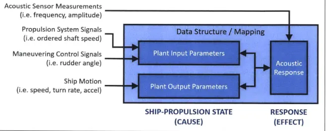
Ship-Propulsion State: In the context of this project, the ship-propulsion state is
the set of input information that is needed to fully define what the ship, ma-neuvering control system, and propulsion system are doing at the time that the acoustic response is being measured. The ship propulsion state will vary in complexity based on the application. As per a finite state machine, it is impor-tant that the ship can only be in exactly one state at a given time. A simplified ship-propulsion state would be comprised of a single variable that simply defines
the amount of power being used for propulsion under steady speed conditions without maneuvering. A more complicated ship-propulsion state, as needed to measure the acoustic responses under unsteady conditions, would contain at least three variables: the ships speed, the power being exerted by the propul-sion system, and the new desired ship speed. Depending on the application, there is flexibility in terms of which variables are used . For example, it may make more sense to use shaft speed [rpm] instead of propulsion power or to use new desired power instead of new desired ship speed. Although well beyond the scope of this project, an advanced system would have a ship-propulsion state that would include even more variables, such as the status of the maneuvering control system, the motion of the ship (in terms of yaw pitch and roll), the pitch angle of the CPP, and possibly even the associated rates of change for each of these variables. The complete list of parameters that make up the ship-propulsion state can be further sub-divided into plant input parameters, and plant output parameters. If unfamiliar with the term "plant" in the sense of control systems, please refer to the definition under "Marine Vessel as a Plant" that appears later in this section.
Data Map: In the context of this paper, data mapping is the process of linking two
or more independent data models sO that they can be cross-referenced. The data contained in the models, along with the method of cross-referencing to-gether, comprise the actual data map. In the context of this project, the data map would link the ship-propulsion state to the corresponding acoustic response. Note that where the ship-propulsion state contains multiple variables, all per-mutations of these variables will need be measured and mapped separately or somehow interpolated. This data map is what defines the cause-effect relation-ship, in which the ship-propulsion state is the "cause" and acoustic response is the "effect". It may be necessary to modify or keep different data maps for different environmental conditions.
Response Threshold(s): These thresholds are effectively the acoustic response
lim-its that the user has defined as being acceptable. Optimization in the context of this project is to maximize performance of the ship while staying just below these limits/thresholds. The data complexity of the threshold should match the complexity and form of data response measurements. For example, if the ap-plication is only concerned with broadband RMS amplitude, then the threshold may be a single value. If the application called for different limits depending on frequency, then the response threshold would be comprised of different values for each frequency band measured in the data map. For example, merchant ships may wish to restrict only the bandwidth of frequencies that interfere with sea-life communications, while a military vessel may be concerned with broadband noise and specific tonals. As per acoustic response, this definition includes internal vibrations and both near- and far-field acoustic noise. The response
threshold value can be either be a static absolute value, or a dynamic variable, such as a percentage of the ambient noise (either measured or historical).
Navigational Aids: In general terms, navigational aids refer to the broad range
of equipment normally installed on most commercial and military vessels that assist in navigating the vessel and avoiding collision. In the context of this dis-cussion, the relevant navigational aids are those systems that will provide the information for the aforementioned ship-propulsion state. Examples of com-mon navigational aids include a GPS (position, heading, and ground speed), a Doppler speed log (speed through the water), and a gyrocompass (heading). Medium sized and larger vessels will also have radar and an echo sounder (to measure water depth). Larger commercial vessels and military vessels will be equipped with an electronic charts system, which automatically takes data from other navigational aids and incorporates the data with digital charts (maps) to help the crew navigate. In addition, military vessels will often have an iner-tial navigation system (INS) that provide heading, pitch, roll, ground speed, acceleration/deceleration, and positional information.
Own-Ship Noise (OSN): Own-Ship-Noise (OSN) is the collective acoustic energy
in form of pressure waves from the host platform's propulsion system, flow noise, and auxiliary systems which are fed back into the host platform's own sensors. This noise interferes with the sensor's abilities to detect and track distant ob-jects.
Acoustic Signature: Acoustic signature is often used in a naval context to describe
the amount of acoustic noise generated by a ship. The meaning changes slightly based on the context as it can refer to a generalized measure of the amount of noise being generated, or it can refer to specific combinations of frequency and amplitude which can be used by more sophisticated sonar systems to identify the specific ship, or class of ship.
Propeller Slip: One way to understand this concept is to visualize a fixed-pitch
mechanical screw advancing into a solid as it is rotated. The pitch of the screw relates to how far it will advance to how much it is rotated by. In this ideal analogy, we expect that the screw will advance exactly as the product of the pitch and the amount it was rotated. Screw propellers, however, operating in a much less efficient fluid medium will never achieve an advance exactly equal to the product of the pitch and rotation. Propeller slip is a measure of how much the screw propeller is falling short of the ideal condition. The mechanical screw in a solid will have no slip while a screw propeller will have a value greater than zero. There will be a steady amount of slip when neither the rotational speed
nor the speed of advance are changing with respect to time. [6]
Forced Propeller Slip: There will always be some propeller slip at steady
condi-tions. However, the amount of propeller slip can be altered from the steady-state value by not allowing the rotational velocity of the propeller and the speed of advance of the propeller through the water to reach their normal equilibrium. For the purpose of this discussion, we introduce a new term, forced propeller
slip, which refers to when the propeller is slipping more than the steady-state
propeller slip because of a mismatch between the speed of advance and rota-24
tional speed (angular velocity) of the propeller. The mismatch can occur in either order. For example, a ship operating at a steady speed alters course us-ing a rudder. The increased drag of the rudder, to together with the increased resistance of "side slip", will slow the vessel down as it turns, however the shaft maintains a constant rotational rate. The forced slower speed will reduce the amount the propeller advances, and therefore causes an increase Propeller slip. Another mismatch can occur when a ship tries to accelerate quickly. The propul-sion system is mechanically linked and has considerably less mass than the rest of the ship and therefore the shaft will be able to reach the new rotational speed relatively quickly. The massive ship will have a lot more momentum and will take significantly more time to reach a new steady speed of advance. In this case, there will be a large amount of propeller slip initially, which will eventu-ally decrease until the ship reaches the new steady speed. This is analogous to a car spinning its wheels when trying to aggressively accelerate; the wheel's angular velocity increases much faster than the car's axial velocity. The resul-tant increased acoustic response that can be seen during forced propeller slip can be shown as it relates to cavitation inception
[141
as well as being directly measured via experimentation[161.
A more detailed explanation, along withassociated equations, are given in Chapter 2.
Cavitation Inception Speed (CIS): This is the lowest sustained vessel speed at
which the propeller(s) causes significant levels of propeller cavitation. As the vapor cavities that are generated above this speed collapse, they significantly increase the noise generated by the propeller. Therefore, Cavitation Inception Speed (CIS) can be considered as a threshold where there is a noticeable dif-ference in generated noise above and below this speed. Note that significant propeller cavitation can still occur at slower speeds, but this is usually at speed transitions.
Unmanned Vehicle (UV): In general an unmanned vehicle (UV) can be
land-based, aerial, or sea-going. In the context of this project, the focus is only on sea-going vehicles. Unmanned surface vehicles (USVs) refer to autonomous or remotely controlled vehicles that operate on the surface of the water. Un-manned undersea vehicles (UUVs) refer to autonomous or remotely based craft able to operate at range or depths below the ocean surface.
Cause-Effect Controller (CEC): A cause-effect controller (CEC) is based roughly
on the concept of a black-box finite state machine, but is different in that for a given state, the levels of the controller outputs associated with that state are not known at the time that the controller is built. Additionally, the values of one or more input into the controller, which determines the states and when state transitions occur are also not yet established. Instead of using pre-determined linear states with predetermined outputs, the CEC creates an experience-based
data map that directly links the state of the system to the predicted response.
For example, in the context of this project, the CEC will conduct calibration runs to create a data map between the ship-propulsion state and the
acous-tic response. At this time, the CEC will also know the user-defined response thresholds. When the controller is given a new desired ship-propulsion state,
for example an increase in the ship's speed, the CEC will look in the data map to determine which ship-propulsion state best matches the new requested state and is also below the response thresholds. The CEC will then order the propulsion system to adopt this new state. This resultant state will be the optimal performance of the propulsion system without exceeding the response
threshold. CECs are designed to be recursive in that they can effectively adopt
many different ship-propulsion states while incrementally approaching the op-timal steady-state. In other words, the system will not simply jump to the new desired speed as quickly as possible, but will instead control the rate at which the ship accelerates to ensure it accelerates as quickly as possible while refraining from exceeding thresholds unnecessarily at each step along the way.
CECs are more complex in terms of hardware than finite state machines as the relationship between input and outputs can not be hard-wired prior to the system being manufactured. The real advantages of determining these values post-manufacturing, is that the same CEC, with the same algorithms, can be used on many different platforms without the need to experientially determine specific values before construction. Additionally, the commonality allows for mass-production without the need to design and build systems custom to the individual platforms. A CEC is also more adaptive to changing conditions as it can be dynamically re-calibrated as required when platform or environmental conditions change.
Marine Vessel as a Plant: In which to make this discussion as straightforward as
possible, established terminology specific to ship maneuvering and control
sys-tems is used where applicable. In the context of controllers, the basic elements
that make up a control system are: a plant, inputs, outputs, and sensors. In-puts act on a plant in which to produce the desired outIn-puts. Therefore, to be consistent with other work in the field with respect to maneuvering and control of ships and submarines, the marine vessel itself is the plant. The inputs to the plant are the systems or sub-systems that can be directly controlled, such as the propulsion power and rudder angle. The outputs would be the resultant
effects on the plant, such as the actual ship's speed and the ship's heading
1171.
With data mapping, certain signals may be an output at one stage of the data mapping process, but become an input signal at a later stage. Also, because a
CEC uses data mapping, it is interested not only in the relationship between the
inputs and resultant outputs, but also the relationships between different inputs and between different outputs. To avoid ambiguity between data going into and coming out of the CEC as inputs/outputs and what are plant inputs/outputs in the context of traditional controllers, the terms "input parameters " and "output
parameters " are used to refer to the latter. The general term: "parameters ",
Proportional-Integral-Derivative (PID) Controller: PID controllers are used
in many applications across many industries. PID controllers are closed-loop feedback controllers that perform very well in real-world applications because of their ability to correct for errors. An error in this context is the difference of the desired output and the actual output of the plant. The proportional function of the controller will increase the correction feedback proportionally to the amount of error so that the controller is neither driving the system excessively, nor failing to provide enough correction to overcome the error. The derivative aspect of the controller measures how quickly the system is recovering, so that it can decrease the level of correction when near the desired output in order to reduce overshoot. Finally, the integral function examines error over time, and therefore corrects for slow, cumulative errors such as drift. When the PID is "tuned", the coefficients that determine the levels of each of these functions are set such that the controller is optimized for the specific application. The PIDs are built with an understanding of the physics that describe the system and tuning is done through modeling. However, there are many applications where there is insufficient knowledge of the physical system, or it is too difficult to model. This is where heuristic approaches are instead used [17]. Methods for tuning difficult-to-model systems have been around for many years and are well established [191, however these forms of tuning are still performed pre-construction. More recently, with developments in computer science, new heuristic methods are available to conducted tuning using algorithms, and with the use of firmware or software, the PID tuners can be tuned and re-tuned at run-time. PID controllers need to determine the error between the desired output and the actual output in which to provide corrections; this is done through feedback sensors.Cause-Effect Proportional-Integral-Derivate (CEPID): While a CEC is able
to determine what the new desired outputs should be, it has no ability for ensuring that it stays in the desired state, nor has the ability to correct for error and stabilize the system. This is where a CEC can be paired with a PID
controller; herein referred to as a Cause-Effect Proportional-Integral-Derivative (CEPID) controller. The CEC portion of the CEPID will resolve the states and determine what the desired state and outputs should be. The PID portion of CEPID would then in turn take the desired output and adjust these outputs to correct for errors, and in doing so, would ensure that the state of the CEC is persevered. With recent advances in heuristic methods of tuning PIDs, this allows for the entire CEPID to be adaptive so it can fully calibrate at run-time on different platforms using common hardware and software.
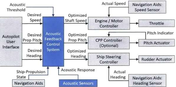
Acoustic Response Control System (ARCS): An Acoustic Response Control Sys-tem (ARCS) is a general term for all integrated sub-sysSys-tems which are used on board ships to provide optimization between propulsion system performance and the acoustic noise generated. With a CEC or CEPID at the core, the ARCS also includes other sub-systems, such as the acoustic sensors, the inter-faces with navigational aids, the user-machine-interface, and the interinter-faces to the ship's maneuvering control and propulsion systems which is usually via the autopilot system. The ARCS may also include data logging sub-systems. The amount of hardware, firmware, and software required for an ARCS will depend on what sensors and navigational aids the host platform has available, and how difficult it is to interface with them.
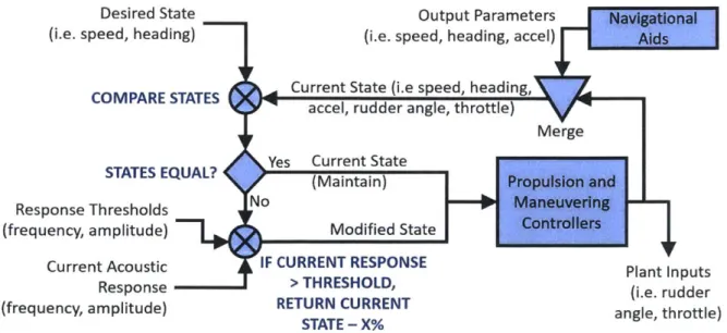
Acoustic Response Control Process (ARCP): Where as an ARCS refers to a system adapted to a type of platform, an Acoustic Response Control Process (ARCP) is a more generic term for how an ARCS determines the cause-effect relationship and how it is used. The ARCP allows ship operators and designers to implement an ARCS that maintains externally transmitted noise (or inter-nally transmitted vibrations) below certain thresholds (response thresholds), while still maximizing the platform's speed and maneuverability within these thresholds. Although discussed in more detail later in this chapter, for most applications, the ARCP has at least two distinct steps. The first stage is
"operate ", where the CEC data map is used to predict and appropriately
mod-ify the command signals to the propulsion and maneuvering systems based on
the given response threshold. Although more of a parallel or alternative process, an ARCS can also be operated in an "ad hoc" mode where instead of predict-ing the acoustic responses, it acts reactively to decrease propulsion orders and adjust maneuvers once they have exceeded the response thresholds.
Input Parameters: As previously discussed, in the context of a shipboard
propul-sion control system, the plant would be the vessel itself. The plant input pa-rameters are propulsion and maneuvering control signals that the ship crew, or autopilot, normally have direct control over, and are used to indirectly control the platform's heading (direction) and speed. Depending on what propulsion system is fitted on the platform, the input parameters will differ slightly, but generally perform the same functions of indirectly controlling the vessel speed and heading. For example, in the case of a traditional ship propulsion system, the plant input parameters (which the crew would have direct control over) would include the shaft speed and rudder angle. By changing the shaft speed and rudder angle directly, the ship speed and heading are subsequently affected indirectly. For a platform equipped with a water jet system, impeller speed and nozzle angle would be the input parameters. Submersibles have additional hydroplane control surfaces which are also plant input parameters and are used to control the vessel's depth. Some vessels have maneuvering thrusters which would use different input parameters (thruster power and direction). On some platforms, propeller pitch can also be controlled directly, and in this sense would also be considered an input parameters for the plant. The term input parameter should not be confused with the line input(s) into the CEC, which includes both
Output Parameters: Output parameters refer to the plant outputs in the
tradi-tional controller context, and therefore are parameters that can be influenced and measured, but not directly controlled such as the ship's speed, heading, or depth. The purpose of a control system like a PID controller is to provide a stable desired output, despite disturbances, through feedback obtained by continually adjusting the plant inputs as required. For example, a control sys-tem designed to help a ship maintain a desired heading (yaw), despite external disturbances such as wind and waves, would use a gyrocompass as a sensor to measure the actual heading (output) and provide this value in the form of feedback. This control system would then compare the actual heading to the desired heading to determine the error, and would then adjust the rudder angle input in which to correct the error. In this case, the focus of the control system is on the primary output being the ship's heading, however changing rudder angle also causes secondary effects such as causing the ship to roll, increased flow noise, and a slight deceleration, some or all of which may be measured. A simple PID controller would not have the need to measure these secondary out-puts as they would be considered separately in other stages of the ship design process. In the case of a CEC, in which to fully measure and identify the sepa-rate ship-propulsion states, many of these secondary outputs become relevant, even if they are not used for feedback to stabilize the plant. Therefore, out-put parameters refer to all relevant plant outout-puts, both primary and secondary that cannot be directly controlled. Note that some output parameters that are used by the CEC do not need to be measured independently, but can instead be calculated where derivative and integral relationships exist. For example, although heading would be measured by a gyrocompass, the turning rate would be the first derivative of the heading with respect to time. The term output parameter should not be confused with the line outputs from the CEC, which includes both input and output parameters in the context of a plant.
1.2
Motivation and Possible Applications
In which to optimize a ship propulsion system, the first step is to identify what parameters are the focus of the optimization. Some examples of the parameters of the propulsion system that designers and platform operators may wish to optimize include:
" Performance Abilities
Top Speed
Maneuverability
/
Turning Rate Acceleration and/or Deceleration * PrecisionMaintain a Static Position Precise Speed and/or Heading
" Fuel Economy
Endurance - Maximum Time on Station Most Economic Speed
" Reliability
Mean Time to Failure Redundancy
/
Robustness * Noise and VibrationAs Experienced by Crew or Passengers Transmitted into the Water
Interference with Own Sensors and Equipment
For each of these parameters, we need to distinguish between two categories of optimizations: 1) those which occur pre-construction during the design phase, and 2) operational optimizations which refer to how the system is employed post-construction. During the initial design phase, several of these parameters will be synthesized into what is considered the best overall design for the specific application, understanding that there will be many inherit trade-offs, as not all parameters can be optimized concurrently. For example, with large merchant ships, the designer will focus on fuel economy at moderately high sustained speeds, and will be less concerned with maneuverability or noise. Designers of warship propulsion systems,
however will focus on top speed, maneuverability, and the noise generated, while being less concerned with fuel economy.
Once a design is finalized, it will have specific capabilities and limitations with respect to the aforementioned parameters. For example, any given ship will have a single most economic speed: the speed where they can travel the largest distance for a given amount of fuel. The ship will also have a single top sustained speed: the highest speed it can maintain without risk of damage to the equipment. There will also be a specific speed where the vessel will have the greatest turning rate. In addition, the vessel will have a specific CIS and also a minimum speed at which the vessel is still able to effectively maneuver on its own. This is an instance where operators of these vessels have the ability to choose between a variety of settings and speeds in which to perform specific operations. The operators are of course confined by the propulsion system's physical capabilities and limitations, but also by their abilities to perfectly time and coordinate multiple system changes under dynamic conditions. This subsequently introduces the concept of operational optimization, where the goal is to optimize how the vessel is best used at different times and in different roles with a fixed propulsion system design. The operational optimization can be quite trivial, such as simply adopting the most economic speed with which to optimize range, but can be much less obvious for multi-variable optimization.
The specific goal of this project is to design a system that will optimize the trade-off between propulsion system performance and the amount of acoustic noise generated in the water. This will be operational optimization as described above, since the intent is not to re-design a propulsion system, but rather to optimize control of it within the established system's physical capabilities and limitations. This is also considered multi-variable optimization, as both the aspects of propulsion system performance, such as speed, and the maximum allowable acoustic noise response are both controllable by the operator. As more aspects of performance are added, such as acceleration and deceleration, the number of variables increases accordingly.
or fuel economy are fairly evident. However, the benefits of optimizing a propulsion system such that certain response thresholds are not exceeded is less obvious. For this reason, an ARCS would be limited to possible applications where limiting the amount of acoustic noise being generated in the water is just as, if not more important, than the overall system's performance. For the applications given, it is assumed that a CEPID controller is being used with a user-set acoustic response threshold. The applications may refer to only the CEC, CEPID controller, or the ARCS where the latter also includes all associated sub-systems and interfaces. Either way, the more encompassing ARCP is being used.
Sensor Optimization: Applicable to submarines, surface combatant ships, research
vessels, survey vessels, and UVs. In general, OSN is reduced at lower speeds, however higher speeds are desired in which to maximize the search coverage. An ARCS with the response threshold set for the frequency and the anticipated returned signal strength for the item being searched for, can then control the host vessel at an optimized speed, thereby giving the best coverage while main-taining the maximum likelihood of sensors detecting the item. Specific examples could include a warship searching for a submarine, or a group of USVs search-ing for the black-box transmissions from an aircraft lost at sea. Note that in which to avoid certain combinations of amplitude and frequency, this does not necessarily require the host vessel to reduce speed, as an increase in speed may also provide a frequency shift in OSN, achieving the desired effect.
Signature Reduction (Stealth): Applicable to submarines, surface combatant ships,
and military UVs. In which to maintain a tactical advantage, ship operators and designers want to minimize the likelihood of being detected by hostile ves-sels, while at the same time not overly restricting their own ability to maneuver (speed, acceleration, and depth/course changes). An ARCS, calibrated with a threshold that matches the anticipated hostile sensor capabilities, can give the host platform the maximum ability to maneuver while minimizing the likelihood of being detected by hostile platforms. Optimization is achieved by carefully
controlling the propulsion and maneuvering control systems, as well as avoiding certain conditions where excessive noise/vibration is generated, such as with propeller cavitation or hull resonances. A military-specific is with the use of acoustic (noise-making) countermeasures that act as decoys against hostile tor-pedoes. The platform employing the countermeasure will want to distance itself from the decoy as quickly as possible, while at the same time, it does not want to generate more noise than the countermeasure. This is where optimizing the ability for the ship to maneuver away from the countermeasure while staying below the response threshold of the countermeasure could provide a significant tactical advantage.
Environmental Consideration: Applicable to merchant vessels, drilling platforms,
pleasure craft/cruise ships, and government-owned vessels that operate in or near environmentally sensitive waters. Noise generated by marine traffic, es-pecially at certain frequencies, has negative effects on certain marine life. It is possible that in the near future, governments will impose prescriptive re-strictions that will limit which types of vessels are permitted in these protected waters, and/or impose speed limitations [15]. As the acoustic noise produced by vessels varies greatly, even within the same class of ship, these prescriptive re-strictions may not provide adequate protection to marine life in some cases, and may be unnecessarily prohibitive in other cases, forcing adequately quiet ships to unnecessarily circumnavigate the protected areas. Given specific frequency and amplitude thresholds for an environmentally protected area, an ARCS can determine if a vessel is able to operate within the required noise thresholds, and if so, allow ships to operate as efficiently as possible within these restrictions. Data logged in the ARCS can be used as evidence of environmental compliance.
Crew and Passenger Comfort: Applicable to all civilian platforms, especially
pas-senger ships and pleasure craft. In addition to externally radiated noise, vibra-tion and noise from the propulsion system is also transmitted inwards through the ship structure where it affects crew-occupied spaces. Health and safety
regu-lations limit crew exposure to noise and vibrations (1981 IMO Code). An ARCS would allow operators to optimize the balance between passenger comfort and platform performance.
1.2.1
Optional Additional ARCS Sub-Systems
Although not within the scope of this project, there are some additional im-provements that can be made to an ARCS, and are worth presenting here to demon-strate additional applications and further areas for improvement.
Active Noise Cancellation (ANC) -In addition to optimally controlling a
propul-sion system, the ARCS could be used together with an Active Noise Cancellation
(ANC) system. The CEC could then dynamically control both the propulsion system
and the ANC. In which to do this, during the "calibration stage" of the ARCP (de-scribed in more detail later in this chapter), the CEC could also capture audio record-ings. The specific matching noise-canceling signal could be generated and mapped to the matching ship propulsion state along with the acoustic response. Outputting the
ANC signals would then be greatly simplified and regarded as an additional output
from the CEC during the "operate stage" of the ARCP.
Control of Internal Vibrations - It was mentioned in Section 1.2 that an ARCS
could also be used to manage internal vibrations for crew and passenger comfort. In which to do this, the ARCS would need to be modified in terms of both hardware and software. The hardware modifications would be to either replace the acoustic
sen-sors with hull-mounted vibration measuring accelerometers, or to simply add these
accelerometers as a secondary sensor. Operators would then need to specify an addi-tional response threshold: vibration response thresholds. Similar to acoustic response
thresholds, the vibration threshold values could be dived by frequency. The
sub-division by frequency simply allows for more precise control, as people are prone to greater discomfort at certain frequencies.
Calibration Health Monitor -Usually during the operate stage of the ARCP, the acoustic sensors are no longer required. As an alternative to turning these sensors off, they could be used to provide validation of the current calibration. It is possible that environment conditions would change, or mechanical defects will occur such that the real-time acoustic response will no longer match the values stored in the CEC. As a minimum, the system will alert the operators that the system has lost confidence in its ability to stay beneath the response thresholds. A more advanced health monitoring function would also either update the original calibration, or begin creating a new one for the new conditions. This function may also provide early warning indications to the operate that something has changed mechanically with their vessel and should be investigated.
1.3
ARCP Description & ARCS Examples
In this section, the Acoustic Response Control Process (ARCP) is discussed in more detail, as well as how this could process could be interfaced into a ship's existing equipment to form an Acoustic Response Control Systems (ARCS).
1.3.1
General Description of the ARCP
Process Premise
Although accurate, using analytical or numerical simulation methods to model and predict the acoustic responses of a marine propulsion system, are specific to the model. There are multiple sources of noise caused by numerous interactions between propulsion, hull, and control surfaces paired with dynamic water conditions that make even steady-state predictions cumbersome. Unsteady and non-uniform flow conditions are even more difficult to model and predict [4]. Analytical and nu-merical simulations are usually built to model one specific class of marine vessel and cannot be easily adapted to other platforms without new simulations or experiments. Additionally, numerical simulations and software-modeled predictions are very
com-putationally demanding, and the results are not available quickly enough to be used in pseudo real-time systems. This discussion presents the ARCP as a adaptive pro-cess that will use a combination of hardware, software, and already fitted equipment (where possible) to learn the cause-and-effect relationship between the propulsion and maneuvering systems, together with the ship's motion (ship-propulsion state), and the resultant acoustic responses generated. The ARCP, in effect, bypasses the need for modeling and a full understanding of all the aforementioned interactions by map-ping the cause-and-effect relationships directly. Because the process includes learning the propulsion and control parameters of the host platform, it can be applied to any platform with minimal variation in the hardware/software configuration using the common ARCP. In other words, by using a process that uses the host vessel's actual movements and real-world measured response to directly develop an approximate re-lationship between them, a vessel-specific response prediction tool can be developed without the need for laboratory modeling or simulation. Additionally, with the use of general experienced-based algorithms, the same hardware and software can be used for different marine vessels, without the need to significantly vary the ARCS designs. Finally, the process will use the learned cause-and-effect relationship to control the host platform with optimal maneuverability so that the user-defined acoustic response thresholds are not exceeded (where possible).
One particularly difficult condition to predict and model is the propeller noise that occurs when the ship is transitioning between speeds. During aggressive
maneuvers and quick speed changes there will be significant
forced
propeller slip asdescribed in Section 1.1. Most ships are able to change the speed and direction of the propulsion system much more quickly than then the actual speed or direction of the entire vessel. This is not only because the propulsion system must change speeds first in which to develop the new thrust in order to change the speed of the ship, but also because of the relative mass differences between the moving parts of the propulsion system and the ship itself. Take for example a large merchant ship with a fixed-pitch propeller that is traveling forward at speed, but wishes to .se reverse-thrust to slow
or stop. Reversing the direction of rotation of the shaft using the engines can be done relatively quickly, and the shaft will achieve a steady rotational speed in the reverse direction long before the ship slows to a halt due to momentum. A ship moving forward with the shaft turning in reverse will produce a very different flow across the propeller and hull than a ship moving in reverse with the shaft also turning in reverse. This is the reason why the state of the propulsion and control systems, as well as the movement of the entire ship all need to be considered and included together in which to create the various ship-propulsion states.
Most propellers are optimized for a steady flow as ships usually spend a lot more time at a given speed, rather than frequently changing speeds. The different flow and interactions will inevitably produce different acoustic responses. Each acoustic
response would also be unique to each combination of hull and propulsion system.
With so many different marine vessels, it becomes necessary to use a singular, common process that can adapt to each unique marine vessel. Before discussing the stages of the proposed ARCP, and how data is managed, it is important to first discuss the terminology and convention that is used for labeling data flow.
Marine Vessel as a Plant
-
Input and Outputs
Although briefly introduce in Section 1.1, this section provides more detail specific to marine vessel control systems and terminology. To create the cause-effect relationships required for the ARCP, the data mapping algorithms will at, different stages. combine signals in different ways. This makes it ambiguous as to what are strictly data inputs and outputs and what are plant inputs and outputs. The defini-tions of plant input parameters and plant output parameters will be used consistently as defined in Section 1.1. However, a plant output parameter may be used as either a data input or an output from the CEC. Making the terminology even more com-plicated, this same plant output parameter may change from being an input to an output of the CEC at different stages of the ARCP. In attempt to provide clarity, a system digram showing a marine vessel equipped with a rudder for maneuvering, and a fixed-pitch propeller for controlling speed is given as Figure 1-2. This figure


![Figure 2-1: Types of Propeller Cavitation - Image from Kerwin, 2010 [10]](https://thumb-eu.123doks.com/thumbv2/123doknet/13836902.443723/63.917.169.724.124.554/figure-types-propeller-cavitation-image-kerwin.webp)
![Figure 2-3: Submarine Wake Field - Image from Chase, 2013 [5]](https://thumb-eu.123doks.com/thumbv2/123doknet/13836902.443723/68.917.245.672.122.507/figure-submarine-wake-field-image-from-chase.webp)
